
Abstract
Soon after the Ballymun Youth Facility was constructed in 2005, it became clear that the abnormally high number of “snagging” issues which had required remediation were not only re-appearing but increasing in amount and severity. The cause of the heave (up to some 10 mm/year) was the oxidation of pyrite in the hardcore beneath the ground-bearing floor slab and exterior paving. The nature and extent of the distress is discussed and the information obtained during the remediation process considered.
Access provided by Autonomous University of Puebla. Download chapter PDF
Keywords
These keywords were added by machine and not by the authors. This process is experimental and the keywords may be updated as the learning algorithm improves.
Introduction
Although there had been a recreational centre in Ballymun since 1998, as part of the regeneration of the area it was decided by Ballymun Regeneration Limited to extend the existing 240 m2 centre off Sillogue Road to provide a new Central Youth Facility (Fig. 1). Also known as the “Reco”, the youth centre is now managed by the Ballymun Regional Youth Resource. The new 1,120 m2 extension includes further offices, a restaurant and various activity rooms at ground and first floor levels, as well as store rooms either side of the entrance to an enclosed courtyard (Fig. 2). In addition, to the north an exercise room/gymnasium adjoins the original sports hall. A roof garden is present at first floor level on the south of the extension. The detailed layout of the ground floor of the new extension is shown in Fig. 3.

Ballymun Youth Facility

Layout of the new Ballymun Youth Facility

Ground floor layout, Ballymun Youth Facility
In 2002 a ground investigation was undertaken consisting of four trial pits which extended to a depth of c. 2.9 m. Below a variable thickness of made ground there was a horizon of typically brown, firm to stiff, glacial deposits (Dublin Boulder Clay). Below some 2.6 m, the material was unoxidised and is commonly referred to as the Dublin Black Boulder Clay. These glacial deposits underlie much of Dublin and provide the founding strata for most of the significant buildings in the city (e.g. Farrell et al. 1995; Skipper et al. 2005; Long and Menkiti 2007).
On 16th August 2004, James Elliott Construction began work at the site, clearing some scrub vegetation, diverting services and preparing to place fill to provide a good working surface. Based on the ground investigation report, Moylan (now Waterman Moylan, the Client’s Consulting Engineers) recommended that the new buildings should be constructed on large mass concrete pier foundations extending down to the Black Boulder Clay (Fig. 4). Moylan recommended the use of ground-bearing floor slabs and that the placed aggregate fill beneath the slabs should have properties compliant with Clause 804 of the NRA 800 Series—Specification for Roadworks.

Section showing structure and foundation layout
Between 3rd November and 13th December 2004, thirty-nine 1.8 × 1.8 m lean mix concrete piers were installed to varying depths, although all extended to the Black Boulder Clay.
Having constructed the 0.6 × 0.5 m ground beams and initial columns, fill was placed in 150–225 mm lifts. As seen in Fig. 5, in the larger areas the fill was compacted with a roller while in more restricted spaces a whacker was used. Having placed the radon barrier and insulation layer, the 150 mm reinforced concrete slab was poured and allowed to harden over the Christmas period.

Fill being compacted by roller, December 2004
This chapter discusses:
-
(a)
The visible development of the distress in the building;
-
(b)
The investigation undertaken in 2007/2008;
-
(c)
The chemistry and other tests carried out on the fill material, both before and after the remediation;
-
(d)
The levelling/elevation survey undertaken between March 2008 and April 2009 to assess the rate/extent of the heave;
-
(e)
The methods the contractors used to remove and replace the deleterious fill;
-
(f)
The effect of the pyritiferous fill on ground concrete, including that observed as the remediation was being undertaken.
Visible Development of the Distress
On 23rd August 2005, a snag list was prepared, as is commonly done towards the end of the construction period. This was updated on 1st September 2005 and contained a number of items typical of those frequently requiring attention before a building is taken over. Practical Completion of the Youth Facility was signed by the Ballymun Architect on 2nd September 2005 and the Centre was formally opened that month. As with most contracts, following Practical Completion there was a year when any defects observed would be repaired by the builder in an interval known as the Defects Liability Period.
Within a month of acceptance of the building, cracks had appeared, and on 6th October 2005 the Client prepared another snag list which drew attention to a number of these. Those recorded were mainly in the stairwell and below windows in the Club Room, Youth Workers’ Office and ground floor corridor. In hindsight it is likely that where the dry lining extended for the full height of the wall only limited bulging was visible, but where the upwards pressure was restricted (e.g. by window cills), overstressing resulted in the visible bulging and cracking appearing more significant.
During early 2006, doors were jamming and dry-lined walls, notably in the Reception area, showed extensive bulging and cracking. Although it is likely there was some cracking of the ground-bearing floor slabs, with fixed floor coverings this would have been difficult to assess and understandably was not examined/recorded. On 3rd August 2006, a further snag list was prepared (Table 1). This identified the positions and lengths of cracks at some 100 locations, many of which extended for over a metre in length.
Whilst minor cracking of plaster/plasterboard is common in new buildings, the large number and the length of the cracks recorded compared with the previous snag list in October 2005 caused considerable concern. Only eleven months after Practical Completion significant ongoing repairs were necessary to allow the continued full use of the building as a youth facility.
The 3rd August 2006 snag list did not include the pronounced upward bend and crack in the ceiling of the Gym adjacent to the mirror wall (Fig. 6). However, it is clear that in the area where the Gym adjoins the original building, as the floor rose it forced the dry lining upwards into the ceiling and, as a consequence, a crack developed parallel to the internal wall. Evidence of the rise in the dry lining of this wall is indirectly recorded in the snag list as Make good wall at top of socket. A photograph taken in February 2008 (Fig. 7) shows 4–5 mm of upward rise at the position of the fixed electrical socket.

Crack in ceiling above mirror approx. 100 mm from rear wall of Gym

Dry lining displaced relative to plug, February 2008
Unfamiliar with the symptoms of sulphate-induced heave, neither the Client nor the builder appreciated the cause of the distress and the likelihood that the problems caused by sulphate-generated heave become worse with time. As a consequence, between September and November 2006 the builder carried out a number of repairs. The distress continued and repairs were continually undertaken by the Youth Centre staff. In this busy environment, however, details of the individual repairs undertaken “in house” were not recorded and no further detailed snag lists were prepared.
In view of the ongoing problems, in October 2007 the Ballymun Regional Youth Resource commissioned an independent consultant’s assessment. In their report, Donnelly Troy suggested the distress may be a result of sulphate heave, which had been identified elsewhere in the Dublin area in 2007. Ballymun Regeneration Ltd then contacted their Engineering Consultants and requested them to undertake a more detailed investigation.
In early November 2007 Moylan undertook a photographic and damage survey. Only some 26 months after the facility was opened, it was noted that the damage included:
-
(a)
Extensive bulging of the plasterboard panels (Figs. 8, 9, 10 and 11);
Fig. 8 
Bulging of plasterboard in Reception area (November 2007)
Fig. 9 
Bulging and cracks in corridor (November 2007)
Fig. 10 
Bulging in part restricted by electric points; Youth Information Room (November 2007)
Fig. 11 
Door frame displaced by bulging plasterboard; Youth Workers’ Office (November 2007)
-
(b)
Cracking in the plasterboard lining (Figs. 12 and 13);
Fig. 12 
Cracking in plasterboard which has bulged and displaced the skirting board (November 2007)
Fig. 13 
Severe crack in the plasterboard in the entrance lobby (November 2007)
-
(c)
Severe cracking of the lining to the east of the window and arching of the cill in the corridor to the Gym (Figs. 14 and 15);
Fig. 14 
Bulge in plasterboard on the north side of window in Fig. 15
Fig. 15 
Gap developing as window cill arches, between corridor from the Gym and the courtyard
-
(d)
A 5–6 mm rise in the floor relative to the threshold at the doorway from the lift area into the courtyard (Figs. 16, 17 and 18);
Fig. 16 
Damage to threshold at doorway from Reception into the courtyard (March 2007)
Fig. 17 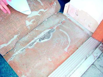
Rise of floor against the threshold into the stairwell (November 2007)
Fig. 18 
Detail of height difference shown in Fig. 17
-
(e)
Spider cracking in the floor of Store 1 (Fig. 19).
Fig. 19 
Cracking of the floor slab in Store 1 (November 2007)


In July 2007 the suppliers of the fill (Irish Asphalt) informed the builder that pyrite was present in some of their product and that this had led to heave on some sites. In view of this and the distress observed at the Central Youth Facility, Moylan instructed Ground Investigations Ireland (GII) to obtain samples of the material from beneath the floor slabs and undertake appropriate geotechnical and chemical analyses to establish if the fill contained deleterious material.
Investigation 2007–2008
A total of seven sampling pits were excavated by GII on 17th November 2007, five within the building and two in the courtyard (Fig. 20). The interior trial pits were some 0.5 m square and excavated through the concrete floor slab, insulation and underlying radon barrier. In the courtyard, the sampling pits were dug after the 65 mm thick porous brick paving and sand screed had been removed.

Locations of seven sampling pits undertaken in November 2007 and trial pits 11 and 12 undertaken in May 2008. Pits referred to as Trial Pits in text
Representative samples were taken in each sample pit (see Table 2). The “A” samples were sent to Geomaterials Research Services (GMRS), now part of Sandberg LLP, while the “B” samples were retained by GII. Samples were also taken by Arup, who were working on behalf of the builder.
Assessment of Samples
In addition to determining the lithology of the material obtained by GII in Nov 2007, a number of physical tests (particle size distribution, PSD), Atterberg limits, water absorption and Los Angeles) were undertaken (Table 3). The chemical testing included total sulphur, acid soluble sulphate and water soluble sulphate.
As seen in Table 3 and discussed below, the material in the interior pits (TPs 1–5) was significantly different from that in the exterior pits (TPs 6 and 7), in regard to colour, physical properties and chemistry. It is understood that the courtyard area was used as a compound during construction and that some of the fill material used to level off the area had been imported from a different source. The fill was therefore a mixture of materials rather than stone from a single source.
From Table 3 it can be seen that:
-
1.
The material in TPs 1–5 was very dark grey to black compared with that in TPs 6 and 7 which was much lighter and browner in colour.
-
2.
The particle size analysis (Fig. 21) indicated that the material generally fell within the grading envelope required for Clause 804 as specified, but that Samples 4 and 5 had slightly more fines (<0.063 mm) than stipulated. However, such a small increase in the fraction may well be a consequence of the placement/compaction processes and would not necessarily have a significant influence on the behavior of the fill if it was inert. As seen in Fig. 21, the middle fraction of Sample 6 (between 2 and 11 mm) was slightly coarser than detailed in Clause 804. Again this would not be considered problematic.
Fig. 21 
Particle size of fill from TPs 1–7 and TP 12 relative to the Clause 804 grading envelope
-
3.
The Atterberg Limit tests, which are undertaken to determine the nature of any clay minerals present and their potential to swell, are assessed only on the material <0.425 mm. The liquid limits obtained, therefore, were based on only 12 to 19 % of the total sample. As seen in Table 3, the results varied between 23 and 30 %—above the thresholds of 20/21 % set in Clause 804. Whilst clearly non-compliant, these values are not sufficiently high to indicate the presence of expansive lattice clay minerals. In addition, all the samples were non-plastic, implying a very low percentage of clay minerals and hence a low swell potential.
-
4.
After the initial examination and particle size distribution analysis, each of the samples was crushed to pass through a 4 mm sieve. The material was then passed over a 0.2 mm sieve and a thin section made of the 0.2–4 mm fragments. The lithologies were determined by point counting using a petrographic microscope.
-
(a)
The microscopic examination indicated that Samples 6 and 7 contained >60 % pure limestone while the other samples contained mainly carbonaceous/bituminous limestone (Table 3).
-
(b)
In all the samples the material identified as pure mudstone accounted for <10 %. However in the interior samples calcareous and carbonaceous mudstone accounted for 43–60 % of the material.
-
(c)
Some of the very calcareous mudstones/argillaceous limestones were laminated with clear bedding partings (shales) and many of the “more massive” calcareous mudstones contained layering/sedimentary banding where the clay-rich horizons were only some 1 mm apart (Fig. 22). These bands were also notably darker in colour and would be expected to be weaker than the general material.
Fig. 22 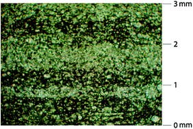
Layers of clay-rich material in a calcareous mudstone
-
(d)
Pyrite, both as cubes/lumps and as framboids, was observed during the microscopic examination. The 5–7 μm framboids were often oxidised with alteration rims up to 10 μm thick. It was noted that some of the framboid seeds were on the outer edges of the alteration rim, suggesting they were transported outwards as ferrous sulphate developed during the oxidation process.
-
(a)


X-ray diffraction analyses (XRD) were undertaken on a representative proportion of the sample. After 35 g had been crushed and milled, a representative 2 g sample was tested to establish a semi-quantitative assessment of the proportions of the various minerals present.
As recommended by Hawkins and Pinches (1987) the sulphide remaining and available to oxidise was established by determining the total sulphur minus the sulphur in sulphate (Table 4).
-
1.
The pyrite content in the interior samples was 2–3 % while in the exterior samples only 1 % was recorded in Sample 6 and no significant pyrite in Sample 7.
-
2.
The calcite content for Samples 1–5 varied between 32 and 35 % while for the two external samples, 77 and 79 % were recorded.
-
3.
Between 2 and 4 % gypsum was recorded in Samples 1–5 and 1 % in Sample 7. No gypsum was detected in Sample 6.
-
4.
The 0.2–4 mm and <0.2 mm fragments were mixed and examined under the scanning electron microscope (SEM). This allowed an optical estimation of the percentage of pyrite in the fine material. As seen in Table 4, this varied between 6 and 14 %. Clearly the fine fraction, being dominantly derived from the mudstones, is likely to contain more pyrite than the coarser material which is likely to be formed of the stronger limestone lithologies.
The chemistry was determined from a representative part of the samples, following BS EN 1744-1 (Table 4).
-
(a)
In Samples 1–5 the total sulphur ranged between 1.34 and 1.56 % S (average 1.44 %), while for Samples 6 and 7 the average was 0.3 % S.
-
(b)
In Samples 1–5 the acid soluble sulphate ranged between 0.43 and 0.55 % SO4 (average 0.48 %), while for Samples 6 and 7 the average was 0.07 % S.
-
(c)
In Samples 1–5 the water soluble sulphate results ranged between 1,575 and 1,614 mg/l SO4 (average 1,599 mg/l SO4), while for Samples 6 and 7 the average was 341 mg/l SO4.
-
(d)
The total sulphur minus the sulphur in sulphate (i.e. the sulphur remaining to be oxidised) varied between 0.83 and 1.13 % S in Samples 1–5 but was only 0.27 and 0.18 % S in Samples 6 and 7 respectively.
The NRA 800 Series (2000) recommended that for material within 0.5 m of concrete/concrete products, the maximum water soluble sulphate content should not exceed 1,900 mg/l SO3, equivalent to 2,300 mg/l SO4. However, as from May 2004 (i.e. before the fill was purchased) the NRA no longer required the water soluble sulphate content to be established but instead stipulated that the acid soluble sulphate content should be measured and should not exceed 0.2 % SO4.
The samples from the courtyard (6 and 7) met both of these requirements and all the water soluble sulphate values met the 2000 criteria. However, all the interior samples had acid soluble sulphate contents of more than double the recommended 0.2 % SO4.
The 800 Series did not consider values/thresholds that could be utilized when assessing sulphate-induced heave; it is assumed this omission was because the writers of the 800 Series anticipated the unbound material would be chemically inert.
After receiving the reports from GMRS in January 2008, an analysis of the results was undertaken and a visit made to the Youth Facility in February 2008. From the assessment of the laboratory results and the field observations it was concluded that the distress was related to sulphate-generated heave as a consequence of the oxidation of pyrite in a dominantly dark grey to black, frequently laminated, calcareous mudrock.
As discussed in more detail in Hawkins (this book), during the chemical process of oxidation ferrous sulphate is formed and sulphuric acid released. The formation of the ferrous sulphate itself causes the initial heave and much of the early fracturing of the mudstone fragments. At the same time, the released sulphuric acid combines with any available calcium carbonate to form calcium sulphate (gypsum). These new minerals may develop in existing cracks within the aggregate fragments, on the aggregate surfaces and/or as euhedral selenite crystals in the open spaces between the fragments.
In these situations, the newly formed gypsum may not cause significant expansion of the fill material. However, the sulphuric acid moving within a fragment may combine with in situ calcium carbonate to form isolated selenite crystals. Such crystals may grow as mobile liquids penetrate into the dilating fragments and/or new crystals may be precipitated in/on laminations in the mudstones and within weak clay-rich horizons in argillaceous limestones.
It is the growth of these selenite crystals which prises open the “layers”, causing dilation of the individual particles and resulting in heave of the compacted fill (Figs. 23 and 24).

Cracks opened by crystal growth

Typical selenite crystal formed in a dilating crack
The SEM examination of the fill material confirmed the presence of ferrous sulphate rims which had clearly created expansion and cracking of the individual fragments. The growth of selenite crystals within the incipient discontinuities could also be seen. It is these crystals which caused the main dilation and heave. In addition, the chemical analyses indicated that significant unoxidised sulphide remained in the fill, which could react in the future and result in further expansion.
Additional Investigation: May 2008
Prior to any decision regarding remediation, it was necessary to confirm the founding level of the mass concrete piers and assess the nature of the material on which the piers were placed. As a consequence, on 21st May 2008 two additional external pits (TPs 11 and 12) were excavated adjacent to concrete piers (Fig. 20). In order to reach the Black Boulder Clay, they were extended to depths of 2.5 and 3 m respectively.
In TP 12, the Brown Boulder Clay extended to 2.55 m. At that depth a 0.15 m thick partially weathered zone separated the Brown from the Black Boulder Clay. The material at the base of the concrete pier was effectively dry, over-consolidated Black Boulder Clay and was estimated to have an undrained shear strength of more than 150 kPa.
A sample of fill was taken from between 0.2 and 0.35 m (see Table 5). Examination of this showed framboidal pyrite was present in the fragments of calcareous mudrock and euhedral selenite crystals were noted in the fine material coating the surface of the particles. The lithologies in the material from TP 12 closely resembled those in TPs 1 to 5 of the previous investigation.
A sample of the Black Boulder Clay was also taken in TP 11, at a depth of 1.9 m (base of the pier). As seen in Table 5, analysis indicated that the total sulphur content was 0.02 % S, the acid soluble sulphate content 0.13 % SO4 and the water soluble sulphate content 166 mg/l SO4.
Level Survey and Monitoring
Following the February 2008 inspection, a digital levelling survey was initiated. Two external datum points were established and the levelling began on the 5th and 11th March 2008. However, the measurements clearly could not take into account the heave which had already taken place; some instances of which are recorded in the photographs from November 2007 (e.g. see Fig. 18).
The locations of the level/monitoring points were constrained by the fact that the building was in use as a Youth Facility and it was important to consider both the safety of personnel and the possibility of damage to monitoring points during the daily activities of the Centre. Initially 45 monitoring points were chosen and studs fitted on floors and ceilings. In addition, in order to establish the relative movement within the rooms, in some places levelling points were positioned on both the ground bearing floor slab and an adjacent concrete cap supporting one of the columns which extended to some 2 m below ground floor level. Studs were also placed on each side of the external doorways to determine the variation in level between the floor slab and the door threshold.
Between 11th March 2008 and 14th April 2009 sixteen readings were taken at the 45 monitoring points and the two datum points. Unfortunately, at some locations the points were damaged such that a total of 11 were only read for part of the 13 month period. Rather than provide all the detailed data here, Table 6 gives an indication of the more significant changes over this period. It should be noted that this is in addition to the rise which had already occurred prior to Mar 2008. The points which had risen by more than 3 mm between March 2008 and April 2009 are shown in Fig. 25.

Levelling points showing a rise of >3 mm between March 2008 and April 2009
In view of the results obtained in the first six months when five showed a rise of more than 4 mm, a further 57 monitoring points were installed and read between 17th November 2008 and 14th April 2009. At nine points the floor rose by at least 2.5 mm over this 143-day period (Fig. 26). The maximum rise of 3.4 mm (L 49) was in the Reception area where there were also rises of 2.6 and 2.9 mm (L 48 and 96). In the café, at L 45, 50 and 55, the rise was 2.6, 3.1 and 2.5 mm respectively while in the Youth Workers’ Office (L 64), there was a rise of 2.6 mm and in the Youth Information Room (L 94 and 95) the rise was 2.5 and 2.8 mm.

Points showing a rise of >2 mm between November 2008 and April 2009
A time versus rise graph has been prepared for the six points which rose by more than 5 mm in 402 days (Fig. 27). Even allowing for possible inaccuracies related to the surveying, it is clear that the relative heave was not consistent.

Six monitoring points which rose by >5 mm over 402 days
In particular:
-
(a)
There was a relatively sudden rise between 18th June and 9th July 2008. In this 21-day period the average rise of the six points was 1.4 mm. At three points (the café, and Locations 15 and 16 in the entrance lobby) the rise was at least 1.8 mm.
-
(b)
Between 9th July and 22nd September 2008, the rise was not generally as fast as the overall average.
-
(c)
There was an apparent drop at two internal and two external locations between 12th January and 2nd March 2009. The records shows that on 9th February 2009 there was an apparent drop of 1.1 mm in Store 1 (Location 38) and 1.6 mm in the Gym (Location 34) while in the courtyard (Locations 7 and 8) apparent drops of 1.4 and 1.1 mm were recorded.
The accuracy of the survey is believed to be within 0.8 mm hence minor “blips” may be associated with the survey techniques. The sudden rise in June/July 2008 would appear to be a consequence of quicker expansion, possibly related to a period of warmer weather. The reason for the apparent drops has not been established. Without further evidence it is considered likely to be related to the survey techniques, possibly a change in staff and/or instrumentation.
Assessment of Concrete, 2008
When TPs 11 and 12 were dug in May 2008, it was noted that some of the concrete showed signs of deterioration and some gypsum crystals were present on the surface of the concrete. As a consequence, on 3rd July 2008, the upper parts of the pits were re-opened and a number of samples were cored from the support beam and mass concrete pillars. Figure 28 shows the poor state of the upper part of the beam in the corner of the courtyard (TP 11) where more than 25 mm of the concrete at the top external corner of the beam could be removed with finger pressure.

Deterioration of concrete at the top of the beam, TP 11, and the nature of the dark deleterious fill adjacent to it
Based on the GMRS report dated 14th August 2008, on the concrete samples from TP 11 it is noted:
-
(a)
Patches of gypsum up to >50 μm thick were present, coating part of the outer surface of the concrete (Fig. 29);
Fig. 29 
Growth of gypsum crystals on surface of concrete
-
(b)
Ettringite extended up to 8 mm into the top of the ground beam (Fig. 30);
Fig. 30 
Abundant ettringite-filled voids, note crack in concrete
-
(c)
In core 6, ettringite was present in voids. As seen in Fig. 31, there was 10.6 % SO4 at 1 mm and 7 % SO4 at 3 mm into the core;
Fig. 31 
% Sulphate extending into concrete pier
-
(d)
Thaumasite was present to a depth of 2.8 mm in the top of the ground beam and in cracks up to 1.8 mm into the concrete (Fig. 32);
Fig. 32 
Fibrous thaumasite in crack around quartz particles, note crack in concrete
-
(e)
At the top of the mass concrete pier, ettringite penetrated into pores and cracks by up to 5 mm. The sulphate profile from the outer surface indicates up to 11 % SO4 by mass of cement (Fig. 33) and elevated sulphates up to 3 mm into the pier.
Fig. 33 
Relationship between % SO4 and distance from top of concrete pier


Analysis of the GMRS report on samples from TP 12 (outside of the Gym) also indicated high values of sulphate near the outer edges of the concrete.
-
(a)
Thaumasite was recorded up to 2 mm from the edge of the concrete at the top of the beam where the sulphate content was 12 % SO4 by mass of cement;
-
(b)
High levels of ettringite were recorded (up to 12 % SO4 by mass of cement) extending up to 5 mm into the mass concrete pier;
-
(c)
An infilled crack 3 mm from the surface was seen in a core from the top of a mass concrete pier (Fig. 34). The profile of SO4 content relative to the concrete surface of the pier is shown in Fig. 35.
Fig. 34 
Crack filled with thaumasite and ettringite, note crack in concrete
Fig. 35 
Relationship between % SO4 and distance from concrete surface
-
(d)
Despite the high percentage of sulphates in the concrete, there was little evidence that significant sulphate attack had already taken place although cracks can be seen in Figs. 30, 32 and 34. However, with such high sulphate contents already present, any further sulphate ingress would be likely to cause disintegration of the affected concrete.


Decision to Remediate
Whilst the level monitoring results were informative, the ongoing distress evident in the building itself was such that it was becoming extremely difficult for personnel to continue to use the facility. In addition to the trip hazards at door thresholds, the jamming of doors, the unsightly cracking, the stress in the area of electric sockets etc., the shock of hearing a sudden loud noise when the bulging dry lining became so stressed that it cracked made it unrealistic for staff to continue to work in such an environment (Figs. 36, 37 and 38).

Distortion of plasterboard in office

Distorted electric service duct

Plasterboard pushed away from plug
The only known practical way of dealing with significant heave due to the generation of sulphates beneath a ground-bearing floor slab is to remove the material containing the pyrite. As described in Canada by Penner, Eden and Grattan-Bellew (1972) in Northern England by Nixon (1978) and in South Wales by Hawkins and Pinches (1987), preventing the oxidation of pyrite in the aggregate and hence the subsequent formation of sulphates which would cause further heave is extremely difficult.
Although flooding and inducing chemical reactions have been considered, flooding is generally impractical and to date, the chemical solutions which have been attempted have been found to be both extremely expensive and dubious in terms of their long term success. Further research work is being undertaken, but as yet there is no substantiated evidence of a practical and effective solution to the problem, other than the complete removal of the pyritiferous material or a change in the design of the structure to accommodate the potential heave. As a consequence, Ballymun Regeneration Ltd decided to remediate the building by removing the imported fill.
Remedial Works
Having provided alternative temporary accommodation for the youth facilities, the original builder commenced remedial works in May 2009. The services were disconnected/removed and, for logistical convenience, the building was divided into three zones (Fig. 39).

Zones for the remediation delineated by the builder
The floor was marked out and then cut into 400 mm blocks which could be handled efficiently by site staff (Figs. 40 and 41).

Floor marked for cutting into manageable blocks

Saw cutting the marked blocks prior to removal
The radon barrier and insulation were taken up and the fill removed using small tracked backactors to load the material onto conveyors for disposal off-site (Fig. 42). Figure 43 shows layers of the replacement fill being compacted.

Removing the fill using a conveyor system

Roller compacting the replacement fill
In order to confirm that the observed differential movement was not related to settlement, at each stage of the works the material supporting the walls and pads was assessed to ensure they had been placed on the Black Boulder Clay and that the bearing capacity of that material was adequate to support the load. This was particularly important in the Reception/café area where existing services had been removed at the time of construction and hence the deleterious fill extended to a depth of some 2.5 m.
During the remedial works, numerous samples of the underfloor fill were taken on behalf of both the Client and the builder, for immediate testing and/or storage for future reference. In addition, while the foundations were exposed the opportunity was taken to check whether the deleterious fill had affected the concrete.
On 11th June 2009 samples of concrete from beneath the fill in Store 2 were taken and sent to GMRS for analysis. Their report indicated:
-
(a)
Samples of the mass concrete foundation pad taken from either side of the room had sulphate values of 9 and 12.6 % SO4 at 1.6 and 1 mm respectively.
-
(b)
The sample from the overlying ground beam had an acid soluble sulphate content of 7.1 % SO4 up to 0.4 mm from the surface while values of >4 % SO4 were measured at a depth of up to 2.7 mm from the surface.
-
(c)
Up to 10.6 % SO4 was present in the outer 0.4 mm of a concrete block taken from the rising wall, with >4 % SO4 extending to a depth of 6 mm from the surface.
-
(d)
No ettringite or thaumasite was identified in the samples from Store 2.
On 1st July 2009, samples were also taken in the area of concrete ground beams beneath the Gym which extended from the original Sports Hall towards the road. Again these were sent to GMRS who reported:
-
(a)
Up to 17.8 % SO4 was found in the foundation pads supporting the beams, extending up to 8 mm into the concrete. Thaumasite-filled cracks were identified up to 4 mm into the concrete.
-
(b)
A concrete chip from the beam at the southern end of the Gym had sulphate values of up to 14 % SO4 and thaumasite-filled cracks were observed close to the surface (Fig. 44). Elevated levels of sulphate extended up to 10 mm into the concrete beams.
Fig. 44 
Thaumasite in beam
-
(c)
A sample block from the outer rising wall had sulphate values up to 6.1 % SO4 with >4 % sulphate recorded up to 25 mm into the block.

On 29th July 2009 concrete samples were taken from beneath the Youth Information Room and lift shaft area. The GMRS analyses indicated:
-
(a)
Samples 1 and 2 had sulphate values of >4 % SO4 up to 6 mm into the concrete.
-
(b)
The concrete chippings in core 4 had >4 % SO4 extending up to 11 mm into the concrete.
-
(c)
In concrete blocks examined from Zone 3, thaumasite was seen to fill pores up to 6.1 mm into the block (Fig. 45).
Fig. 45 
Thaumasite filling void 6.1 mm from concrete surface

On 8th October 2009 concrete samples were taken from Store 1. The results of the analyses indicated:
-
1.
A maximum sulphate content of 16.6 % SO4 with >4 % SO4 extending into the concrete for up to 10 mm.
-
2.
Thaumasite and ettringite up to 5 mm from the outer face of the concrete.
In view of the extent of sulphate penetration into the concrete/concrete blocks a decision was made to scabble the ground beams where the concrete was exposed during the remedial works. In part this was to ensure that sulphates did not extend as far into the beams as the steel reinforcement. After the outer 1–5 mm had been removed by scabbling, the concrete was coated with a Fosroc product to inhibit further moisture entering into the cementitious material and thus minimise the potential for any future development of sulphate.
Although the concrete block rising walls were also scabbled to remove the high percentage of sulphate in the outer few millimetres, the addition of a Fosroc product was considered desirable to reduce any further ingress of moisture into/through the concrete which could affect the carbonation process in the concrete. Although only limited cracking which could be specifically related to sulphate attack was evident and it was considered that, having minimised the potential for any future chemical reactions, should the outer part of the blocks experience some deterioration this would not compromise the longevity of the structure.
Horizontal Crack
During the remedial works, particularly in Zone 3, it was noted that a horizontal crack with an aperture of some 1–5 mm was present around much of the outer wall particularly beneath the Games Room and Kitchen/Café area. This horizontal crack had no relationship with the damp proof course but indicated a clear parting of the rising wall approximately 0.5 m below ground level.
It became apparent during the works that the sulphates had not only caused a rise in the ground-bearing floor slab by vertical expansion, but horizontal expansion pressures had also been generated. The expanding fill, pressing against the external wall, where there was no smooth-sided gap between the floor slab and the rising wall, caused the whole superstructure to be lifted away from the lower part of the supporting walls.
When the fill was taken out, and hence the lateral pressures removed, the superstructure settled back. The maximum aperture of the horizontal crack is not known but elsewhere in Dublin openings of up to 23 mm have been observed.
Quality of Replacement Backfill
Before a decision was made as to which quarry should be used for the replacement fill, test certificates were requested. On the basis of the results, the quarry selected as potentially suitable was visited by the Client’s team. Having satisfied themselves that the quarry was dominantly limestone, with some chert nodules, samples were selected by the team and independently tested. The results of the chemistry testing on the replacement fill (prior to and at the time of placement) are given in Table 7.
As can be seen from this table, the results indicate the replacement fill is effectively chemically inert. In addition, the SEM imagery did not detect any significant pyrite, although small cubes/lumps were observed, locked into a dense limestone.
A comparison with the original fill taken at various dates during the remediation is given in Table 8. It can be seen that some 1.5–2 years after the initial samples were taken in November 2007, the 16 samples tested in 2009 had lower average pyrite contents while the average gypsum had increased from 2.8 to 5.3 %.
Summary and Conclusions
Within months of the completion of the Ballymun Youth Facility in 2005, significant cracking occurred and doors began to jam. Within a year of Practical Completion a snag list identified more than 130 cracks, some of which extended for the full height of the room. At the 100 locations recorded in the snag list, damage included cracks in plasterwork, bulging of walls, separation of skirting boards and arching of window cills. Initially the cause of the damage was not clear and it was assumed to be related to normal plaster shrinkage or workmanship issues. However, despite ongoing repairs, the distress continued.
Chemical analyses of five samples of fill taken from beneath the building in late 2007 indicated high levels of total sulphur, acid soluble sulphate and water soluble sulphate while the X-ray diffractograms showed 2–4 % pyrite. The SEM studies proved an abundance of framboidal pyrite in the calcareous mudstone which formed the dominant lithology in the fill. In places the pyrite had already oxidised such that ferrous sulphate rims had formed around the framboids/framboid seeds, causing expansion and cracking of the individual particles. Gypsum in the form of selenite was seen as crystals within incipient discontinuities in the aggregate particles, where clearly the crystal growth had caused dilation. Gypsum was also seen in some veins and as euhedral crystals in the fine material around the individual aggregate fragments.
As the chemistry indicated the potential for further significant heave in the future, Ballymun Regeneration Ltd decided to move the Youth Centre into temporary accommodation and replace the deleterious fill. The source for the replacement fill was chosen based not only on the test results provided by the quarry, but also a site visit by the Client’s consultants when they selected samples for independent testing to confirm the suitability of the aggregate.
During the removal of the pyritiferous material, the opportunity was taken to examine concrete which had been in contact with the fill. Although the structural integrity of the concrete had not been compromised, the development of sulphates (including ettringite and thaumasite) had extended sufficiently into some concrete/concrete blocks that it was considered prudent to scabble and coat the outer surfaces to ensure the development/movement of sulphates could not cause a problem in the future.
The remedial works were successfully completed in December 2009 and the Youth Facility was formally re-opened on 14th January 2010 by President Mary McAleese.
References
British Standards Institute (2010). BS EN 1744-1:2009. Tests for chemical properties of aggregates. Part 1: Chemical analyses. BSI, London.
Farrell, E. R., Coxon, P., Doff, D., & Pried’homme, L. (1995). Genesis of brown boulder clay in Dublin. Quarterly Journal of Engineering Geology, 28, 143–152.
Hawkins, A. B., & Pinches, G. M. (1987). Sulphate analysis on black mudstones. Géotechnique, 37(2), 191–196.
Long, M., & Menkiti, C. O. (2007). Geotechnical properties of Dublin Boulder Clay. Geotechnique, 57(7), 595–611.
Nixon, P.J. (1978). Floor heave in buildings due to the use of pyritic shales as fill material. Chemistry and Industry, 4, 160–164.
Penner E., Eden, W.J., & Grattan-Bellew, P.E. (1972). Expansion of Pyritic Shales. Canadian Building Digest, National Research Council of Canada, 152,1–4.
Skipper, J., Follett, B., Menkiti, C., Long, M., & Clarke-Hughes, J. (2005). The engineering geology and characterisation of Dublin Boulder Clay. Quarterly Journal of Engineering Geology and Hydrogeology, 38, 171–187.
Acknowledgments
The authors would like to thank Philip Maguire and Ballymun Regeneration Ltd for permission to publish the chapter and their help in its preparation. We are also grateful to Waterman Moylan and in particular to Austin Murphy for his meticulous record keeping, to Mike Eden of Sandberg for a number of the SEM photographs and to Marcus Hawkins who prepared the diagrams.
Author information
Authors and Affiliations
Corresponding author
Rights and permissions
Copyright information
© 2014 Springer International Publishing Switzerland
About this chapter
Cite this chapter
Hawkins, A.B., Stevens, M. (2014). Problems Associated with the Use of Pyritiferous Fill at Ballymun Youth Facility, Dublin. In: Implications of Pyrite Oxidation for Engineering Works. Springer, Cham. https://doi.org/10.1007/978-3-319-00221-7_4
Download citation
DOI: https://doi.org/10.1007/978-3-319-00221-7_4
Published:
Publisher Name: Springer, Cham
Print ISBN: 978-3-319-00220-0
Online ISBN: 978-3-319-00221-7
eBook Packages: Earth and Environmental ScienceEarth and Environmental Science (R0)