
Abstract
DC plasma spraying stands out as one of the most widely used thermal spray techniques for a broad range of applications including tribological and wear resistance, corrosion and/or oxidation resistance, thermal protection, biomedical applications, and the deposition of free-standing spray-formed parts. The technology is based on a simple concept of in-flight melting of the material to be sprayed injected into a plasma stream in the form of fine dispersed powder, solution or suspension, followed by the deposition of the molten droplets on the substrate to be sprayed on which they form splats freezing on impact. The coating is thus formed through the accumulation of successive layer of splats which can grow to hundreds of micrometers thick and more.
Because of the intensive R&D efforts in this field over the past few decades, the presentation of this technology has been split into two complementary chapters, with “Chapter 8 DC Plasma Spraying –Fundamentals” dedicated to a discussion of basic concepts behind the technology. The present chapter follows up with a description of DC Plasma Spray technology under a wide range of conditions including Atmospheric Plasma Spraying (APS), Controlled Atmosphere Plasma Spraying (CAPS), Vacuum Plasma Spraying (VPS), and Ultra-Low-Pressure Plasma Spraying (ULPPS). Detailed discussions of substrate preparation, coating formation, and coating characterization are covered in Part III, while process integration including powder/wire or cord preparation, instrumentation, industrial applications, and process economics are covered in Part IV of this book.
Access provided by Autonomous University of Puebla. Download chapter PDF
Keywords
- DC plasma spraying
- Atmospheric plasma spraying
- Controlled atmosphere plasma spraying
- Vacuum plasma spraying
- Ultra-low-pressure plasma spraying
- Wear-resistant coating
- Thermal barrier coatings
1 Introduction
As discussed in Chap. 8, DC plasma spraying stands out as one of the most widely used thermal spray technologies that is broadly applicable for tribological and wear resistance, corrosion and/or oxidation resistance, thermal protection, biomedical applications, and the deposition of free-standing spray-formed parts. The technology is based on a simple concept of in-flight melting of the material to be sprayed in the form of fine dispersed powder, solution or suspension, followed by the deposition of the molten droplets on the substrate to be sprayed on which they form splats freezing on impact. The coating is thus formed through the accumulation of successive layer of splats which can grow to hundreds of micrometers thick and more.
The motivation for coating process can be summarized by the following needs:
-
(a)
Improve functional performance, for example, by allowing higher temperature exposure through the use of thermal barrier coatings.
-
(b)
Improve component life by reducing wear due to abrasion, erosion, and corrosion.
-
(c)
Extend functional use by rebuilding the worn part to its original dimensions avoiding the need for replacing the entire component, for example, a shaft or axle.
-
(d)
Reduce component cost by improving functionality of a low-cost material with an expensive coating. In each of these uses of coating technologies, there should be no, or minimal, machining required of the coated part.
Because of the intensive R&D efforts in this field over the past few decades, the presentation of this technology has been split into two complementary chapters, with “Chapter 8 DC Plasma Spraying –Fundamentals” dedicated to a discussion of basic concepts behind the technology including properties of electric arcs, arc stability, and electrode erosion. This is followed by a description of the principal design features of DC plasma sources used in plasma spray operations. The important topic of gas and particle dynamics in DC plasma spraying is discussed next with emphasis on plasma jet dynamics, ambient gas entrainment mechanism into the plasma jet, and its effect on the flow and temperature fields in the plasma jet. The discussion on particle dynamics builds on “Chapters 4 Plasma-particle momentum and heat transfer” and “Chapter 5 Gas and Particle Dynamics in Thermal Spray” covering such topics as particle trajectory and thermal history calculations and plasma–particle interactions.
The present chapter follows up with a description of DC Plasma Spray technology under a wide range of conditions including:
-
Atmospheric Plasma Spraying (APS)
-
Controlled Atmosphere Plasma Spraying (CAPS)
-
Vacuum Plasma Spraying (VPS)
-
Ultra-Low-Pressure Plasma Spraying (ULPPS)
Detailed discussions of substrate preparation, coating formation, and coating characterization are covered in Part III, while process integration including powder/wire or cord preparation, instrumentation, industrial applications, and process economics are covered in Part IV of this book.
2 Atmospheric Plasma Spraying
Atmospheric Plasma Spraying (APS) is the simplest form of plasma spraying operations in which the plasma torch is operated in an open discharge mode generating a high temperature, high velocity plasma jet in which the coating material is injected in the form of fine powder, liquid solution, or suspension. As the individual particles are entrained by the plasma gas, they are heated, melted, and accelerated by the flow before being projected at high speeds toward the substrate on which they impact forming splats which are the building blocks of the coating. When feeding solutions or suspension, the liquid component is first evaporated leaving behind small gains of solid material that on further heating are partially or completely melted before being projected toward the substrate forming the coating. As will be discussed further in this section, the quality of the coating depends on a large number of parameters reflecting the plasma jet characteristics, the powder/precursor properties and its injection conditions, the substrate preparation, and stand-off distance between the plasma torch and the substrate. By operating a TS system in an open discharge mode, the entrainment and mixing of ambient air with the plasma jet offers an added complexity to the process due to the quenching of the jet by the entrained air, resulting in a modification of the jet structure and of the temperature field to which the sprayed particles are exposed. While the effect is of no serious consequences when spraying oxide ceramics, it can be responsible for the partial oxidation of metallic particles and oxidation-sensitive ceramics. However, the economic advantage of the APS process and the lack of any limitation regarding the shape and dimensions of the part to be coated in the open discharge mode of operation make it one of the most competitive and commonly used configurations of the spray of ceramics and high melting temperature metals and alloys.
2.1 Atmospheric DC Plasma Spraying Equipments
The principal components of a DC plasma spray system/process are illustrated in Fig. 9.1. Central to this system is the DC plasma torch which was described in great detail in Sect. 8.3 “Plasma Torch Design.” The system also constitutes an electrical power supply, high frequency starter, gas supply, powder or liquid/suspension feeder and a closed loop high pressure cooling water circuit. A Process Control Console allows adjustment of the operating parameters, that is, arc initiation, the control of arc current, plasma gas, and powder and carrier gas flow rates. The Control Console also houses safety interlocks to avoid starting the arc without cooling water flow or primary plasma gas flow. Auxiliary equipments are necessary for system operation, which include a manual or robotic torch controller, substrate support, spray booth, and general instrumentation and control subsystems.

Schematic of a plasma spray system showing plasma torch, cooling water supply, gas supply, power supply, spray powder feeder, and control unit
The power supply is usually a current controlled rectifier. While thyristor-controlled rectification is still being frequently used, modern rectifiers are designed using high frequency switching to reduce the size of the inductor necessary for obtaining a smooth DC current. The problem with thyristor-controlled rectifiers is that there is an inherent harmonic of the DC current which is noticeable in the jet as a 300/360 or 600/720 Hz power ripple. Inverter type power supplies rely on high frequency (>15 kHz) switching to deliver smooth current. The open circuit voltages are typically in the 100 V to 200 V range. As a rule of thumb, it is necessary to have an open circuit voltage about twice (2×) the working voltage. To establish the arc initially, a starting circuit is employed, consisting of a high voltage transformer and capacitor, which allows the breakdown of a spark gap and the initiation of the current flow. However, this type of starter generates a high frequency noise signal detrimental to electronic devices, which must be disconnected automatically during arc start-up stage.
The plasma gas supply consists of two or more (up to 12 or 24) high pressure gas cylinders, with the gas flow rates controlled separately at the control console, frequently by means of sonic orifices or mass flow controllers. The gases are mixed and introduced into the plasma torch. The primary gas should be heavy and must efficiently push the arc root downstream. The most frequently used primary gas is argon because of its low breakdown voltage for arc ignition and low energy density. It is often necessary to add a secondary gas such as hydrogen or helium to the basic argon flow, to increase the plasma power density, gas velocity, and the heat transfer rates to powders. Nitrogen, carbon dioxide, or water vapor are also used as secondary gas, or even as primary plasma gases in specially designed torches. For applications requiring high deposition rates and where high-power levels are desirable, mixtures of nitrogen and hydrogen are used. It must be emphasized that it is the mass flow rate that is important for controlling the arc inside the torch and not the volumetric flow rate. Increasingly, ternary gas mixtures are being also used as plasma gases, such as Ar-H2-N2 or Ar-H2-He, to tailor the plasma properties for optimal heat and momentum transfer to the particles while keeping electrode erosion at acceptable levels [Janisson et al. (1998); Fauchais and Vardelle (2003); Fauchais (2004)].
The cooling water supply consists of a closed-loop, de-ionized or distilled, water circuit. Depending on the plasma torch design, the water pressure should be maintained in excess of 1 MPa (146 psig), preferably between 1.2 and 1.7 MPa (175–247 psig) and cooled by a heat exchanger placed on the return line of the cooling water circuit. The water-flow control valve should also be placed on the return line of the cooling circuit in order to maintain a high backup pressure in the torch circuit to avoid film boiling under the high heat flux conditions in the anode region. The necessary cooling water flow rate is determined depending on the torch power rating, the ambient cooling water supply temperature, and the allowable temperature rise. For safety reasons, cooling water temperature at the exit of the torch should not be allowed to exceed 50–60°C.
The spray powder supply system consists of a powder hopper, which is heated and vibrating to avoid powder agglomeration and moisture pick-up. The powder feeding rate is controlled using either a rotating screw system or a rotating wheel or disc with a scraper or a slot, mounted at the bottom of the powder hopper. From the feeder, the powder is transported by the carrier gas to the torch using a pneumatic line. Depending on the powder particle size distribution, the material density, and the i.d. of the powder injector probe, the required powder injection velocity should be set for optimal particle trajectory in the plasma stream. Based on the required powder injection velocity and the i.d. of the powder injector, the carrier gas flow rate is calculated using a mean velocity of the carrier gas in the injector that is double (2×) that of the particle injection velocity. Once the carrier gas flow rate was set, the i.d. of the powder transport line is calculated with the objective of maintaining a carrier gas velocity in the transport line above (10 m/s) to avoid particle deposition and partial blockage of the transport line and/or pulsating slug flow. Assuring good and steady powder flow by avoiding any accumulation of powder in a section of the supply line where the flow could slow down is of utmost importance because next to the torch operational stability, the stability of the powder injection has the strongest influence on coating quality.
Additional ancillary equipments consist of robots moving the torch and the part to be sprayed such that the particle-laden plasma jet impinges as much as possible perpendicularly to the surface of the part being sprayed. A spray booth with an efficient filtration system is necessary to avoid contamination of the environment with hazardous fumes generated during the process through partial vaporization of the powder and its subsequent condensation in the form of nanometric-sized fumes. A spray booth also shields the operator from the ultraviolet radiation from the plasma jet and the relatively high level of acoustic noise generally associated with the process. A detailed analysis on plasma spray system integration is given in Chap. 18 “System Integration.”
2.2 Plasma Spraying Parameters
The coating properties, as for most thermal spray processes , depend on a large array of process parameters. These can be grouped under the following five primary sub-systems as presented in Table 9.1.
-
Plasma torch parameters are centered around their specific design and independent operating conditions, including torch current, plasma gas composition and flow rate, cooling water pressure, and flow rate. The corresponding torch-dependent parameters are the mean torch voltage and standard deviation which is an indication of the level of arc fluctuations, and the overall torch energy efficiency.
-
Plasma jet characteristics, which are dependent on the torch/nozzle design and torch operating conditions such as temperature and velocity distributions and jet stability, thermal conductivity, and viscosity of the plasma gas.
-
Spray particle parameters include material properties such as density, thermal conductivity, specific heat, melting and vaporization temperatures, latent heat of melting and of vaporization, surface tensions, and emissivity of the molten material, molten material. To this, the collective powder properties need to be added which includes particle size distribution (PSD), its mean and standard deviation, particle porosity, morphology, and flowability.
-
Particle injection parameters, which include injector dimensions, position and orientation with respect to the plasma flow, as well as carrier gas flow rate. These would translate into dependent variables of particle injection such as particle injection velocity and temperature. Powders being composed of particles of different sizes and shapes will be injected into the plasma with a broad range of particle velocities and spray patterns for a given carrier gas flow rate.
-
Substrate parameters, such as substrate material, its thermophysical properties, substrate shape, and its principal dimensions as well as surface preparation in cleanliness and roughness. It is also necessary to avoid excessive gas adsorption which can interfere with splat formation and reduce coating adhesion. Substrate temperature is also another important substrate parameter which has to be closely controlled during the spray coating operation due to its impact on splat formation and the properties of the coating obtained, as discussed later in Sect. 9.2.4. shape.
2.3 Substrate Preparation
Thermal spraying begins with proper surface preparation, which is absolutely essential. Steps must be undertaken correctly in order for the coating to perform the design expectation [Davis (2004)]. Without surface preparation failure of the coating becomes highly probable because coating adhesion quality is directly related to the cleanliness, the roughness, and sometimes the proper machining for optimal coating performance.
The coating material and the nature of the substrate are the major factors in determining what kind of surface preparation is necessary to achieve a resistant bonding. It is also important to keep in mind that the coating must never end abruptly at the part extremity (see Fig. 9.2a), where it may act as a stress raiser and where cracks will develop, especially when loads are applied. Coating at the extremity of a part should present a narrow-feathered band, rather than a sharp edge (see Fig. 9.2b).

Coating and substrate preparation: (a) wrong design with the coating abruptly ending at the extremity, (b) right design with a narrow-feathered band, (c) recommended undercut machining, (d) edge machining, (e) grooved substrate, (f) smooth substrate. Reprinted with kind permission from ASM International [Davis (2004)] and American Welding Society [Thermal Spraying (1985)]
Conventional machining: turning or milling allows undercutting the substrate target area to accept the coating. As without undercutting, the coating deposited must never end abruptly. In the undercuts the corners must be chamfered, or its cutting edge removed before spraying. The chamfer angle should be about 30° (see Fig. 9.2c) or up to 45° (see Fig. 9.2d). Sharp corners capture loose spray particles, dusts, and debris resulting in porous areas.
Machining is also used for creating grooves or threads into the surface to be sprayed (see Fig. 9.2e) to restrict shrinkage stresses and to disrupt the lamellar pattern of particle deposition in order to break up the shear stresses parallel to the surface (see Fig. 9.2f) [Thermal Spraying (1985)]. This technique is mainly used for spraying thick coatings or coatings on a substrate with a short radius. The surface is generally roughened after grooving. Two types of grooves are used: V-shaped ones when the V angle relatively to the part surface is 70° with the root rounded or U-shaped grooves, between 1.1 and 1.4 mm in width.
As discussed in the review paper by [Chandra and Fauchais (2009)], the vast majority of substrates used in thermal spray applications are metallic. Metals (except gold and platinum) or some alloys have oxidized surfaces even without preheating them (native oxide). Unless oxide layers are removed prior to spraying, particles impact on the oxide layer existing on the substrate surface. Then for the following deposited layers, particles also mostly impact on oxides because particles have been oxidized either in-flight or during deposition in air atmosphere. Most studies were performed on smooth surfaces where the observation at the nanometer scale is possible and where the particle flattening can be followed. Several authors have pointed out that mean surface roughness Ra of smooth surfaces of metals (except Au and Pt) or alloys increases at the nanometer scale with substrate preheating. [Fukumoto et al. (2005)] have noted that when a surface was polished to a particular average roughness Ra, coating adhesion was not as high as it was when preheating produced the same roughness. To more accurately characterize the substrate surface, [Fukumoto et al. (2005)] introduced another index of surface topology: skewness (Sk), which is a measure of the symmetry of the peaks and valleys of the surface roughness of the substrate. The skewness increases from negative values to positive ones upon preheating a polished surface and splat shape changes correspondingly from fingered to disk shaped. [Cedelle et al. (2006)] have shown for a 304 L stainless steel substrate that changes in surface topography in the nanometer range have a large effect on the static wetting behavior of molten metal droplets placed on its surface. Hence substrate preheating does not modify just the chemical composition and thickness of the oxide layer on the metallic substrate, but also its physical aspect, which plays a key role in the behavior of impacting particles. For Sk > 0 (more peaks than undercuts) obtained for 304 L stainless steel, preheated at 673 K by a D.C. plasma jet [Fukumoto et al. (2005)], [Cedelle et al. (2006)], [McDonald et al. (2007)] or a laser (with a power density over 50 MW/m2) [Fukumoto et al. (2006)], the resulting zirconia splats were disk shaped and not extensively fingered as when sprayed on the cold substrate (Sk ~ 0). For example, Fig. 9.3 represents the surface topography of 304 L stainless steel after polishing at room temperature (Fig. 9.3a) and preheated at 673 K (Fig. 9.3b). The preheated surface with Sk ~ 1 presents more peaks than valleys compared to the not-preheated polished one where Sk ~ 0. When the substrate surface is treated with a laser, average roughness Ra and skewness Sk vary with energy density and number of laser pulses.

Surface texture of 304 L stainless steel 1×1 μm2 (a) kept at room temperature after polishing, Ra =0.6 nm and Sk = ± 0.1 (b) preheated by a DC plasma torch (Ar-H2) at 250 °C during 120 s, Ra = 3.5 nm and Sk = 0.9. Reprinted with kind permission from Elsevier [Cedelle et al. (2006)]
Any surface, especially in the presence of an oxide layer, is polluted by adsorbates and condensates. Upon impact of a molten droplet on the substrate, it flattens trapping the adsorbates and any vapors between the flattened droplet surface and the substrate giving rise to the development of a sharp pressure wave which can reach up to thousands of MPa for a few hundreds of nanoseconds. More generally, the presence of an evaporable substance on the surface affects significantly the flattening process, through the droplet-substrate wettability and the contact resistance created between the flattening particle and substrate [Li et al. (1998), (1999), (2007); Fukumoto et al. (2006)].
A detailed study of adsorbates and condensates at the substrate surface was reported by [Li and Li (2004)]. Often, water is the main component at the surface. Its adsorption on an oxide surface is usually the result of one of three possible mechanisms, or combinations of them, depending on the temperature, the intrinsic reactivity of the surface, and the number of defect sites at the surface [Henrich and Cox (1994)]:
-
Physisorption of molecular water
-
Chemisorption of molecular water
-
Chemisorption of molecular water followed by dissociation
Physisorption corresponds to very weak interaction between the substrate and adsorbates, while chemisorption is much stronger and may involve partial charge transfer, which more readily leads to dissociation [Henrich and Cox (1994). Stronger adsorption occurs at steps and defects and new OHy radicals, resulting from dissociation, bond with a surface metal ion.
When the surface is heated over a critical temperature, adsorbed water species, as well as other adsorbed liquids, will be desorbed. This desorption process is linked to assorted products, surface structural features, and surface materials. Physisorbed molecular water is generally completely removed by preheating above 150 °C. However, with chemisorbed water, the thermal desorption temperature depends on adsorbed features and the subsequent desorbed product. For most oxide-covered metal surfaces, chemisorbed occurs at temperatures ranging from 127 to 320 °C as summarized in the table given by [Li and Li (2004)] for several oxides and nominal metal surfaces. The authors [Li and Li (2004)] underline that this desorption temperature range is in good agreement with the substrate preheating temperatures reported as transition temperature over which splats are disk shaped [Chandra and Fauchais (2009); Fukumoto et al. (2005); Cedelle et al. (2006); McDonald et al. (2007); Fukumoto et al. (2006)].
In an attempt to identify the effect of the nature of the adsorbent on the splat formation, Li and li (2004) brushed a stainless-steel substrate with either xylene, glycol, or glycerol prior to thermal spraying. The results showed that regular disc-shaped splats were obtained in all cases provided that the substrate preheating temperature was 50 oC above the corresponding boiling temperature of the organic adsorbent.
An interesting question was how long it takes after preheating and evaporating of all adsorbates and condensates, for the surface to be recovered again by adsorbents from the surrounding atmosphere. To answer the question, [Fukumoto et al. (2006)] exposed stainless steel 304 L substrates, which were heated to a temperature where disk-shaped splats were obtained, to ambient air at room temperature for different period of time (24, 48, 72, 96, and 120 h). They investigated the effect of elapsed time after heating on the splat morphology change. The result given in Fig. 9.4 shows that for up to 24 h following the heating and removal of the adsorbates, a high fraction of disk-shaped splats could still be observed. For longer periods, beyond 24 h, the fraction of disk-shaped splats began to decrease. Finally, the fraction of disk splat decreased to less than 50% over 72 h and more from the initial surface cleaning from adsorbates. Of course, both Ra and Sk of a once-heated substrate kept in an air atmosphere at room temperature for a long time were unchanged.

Relationship between elapsed time after heating to 723 K and fraction of disk-shaped splats [Fukumoto et al. (2006)]. (Reprinted with kind permission from Springer Science Business Media copyright © ASM International)
A study of the particle flattening behavior under reduced pressure was reported by [Fukumoto et al. (2007)] with the objective of determining the effect of pressure on desorption of adsorbates and condensates (plasma spraying under soft vacuum). Measurements made of the pressure below which splats became disk-shaped for different materials were used as indication of gas desorption. These have shown that desorption probably occurs at pressures between 92 and 26 kPa, depending on substrate material. A laser can also achieve evaporation of adsorbates and condensates provided its energy density is over a certain threshold [Coddet et al. q1999; Costil et al. (2005)].
According to [Dong et al. (2013)], the elimination of adsorbates and condensates can also be achieved by blasting the substrate surface with dry-ice (CO2 at −79 °C). The process as schematically represented in Fig. 9.5 involves three steps. The first (Fig. 9.5a) involves the cooling and solidification of the adsorbates and condensates. This is followed by the breakage (Fig. 9.5b) and the ejection from the surface (Fig. 9.5c) of the solidified adsorbates and condensates as a result of their bombardment with dry-ice granules.

Schematic representation of the elimination of adsorbates and condensates by dry ice pellet blasting (a) cooling of the substrate by impacting ice pellets, (b) solidification of adsorbates and condensates, (c) ejection of broken solid adsorbates and condensates [Dong et al. (2013)]. (Reprinted with kind permission from Elsevier)
Preheating the substrate over the transition temperature (most probably the temperature above which adsorbates and condensates are removed) modifies the oxide layer thickness, composition, and roughness.
When the substrate is preheated in a furnace with a controlled atmosphere and well-defined conditions (heating rate, maximum temperature, preheating time, oxygen partial pressure, or controlled atmosphere), oxide layers are reproducible. On the other hand, if the surface is heated with an electrical resistance while being exposed to ambient air, the oxide formation is less well controlled since the atmosphere in contact with the surface contains oxygen molecules and different amounts of water vapor. Moreover, contact between the substrate and the resistance heater used to raise its temperature is not perfect, resulting in uneven heating.
When a spray torch is used to preheat the surface, even if the mean heating rate and final temperature can be well defined, the local temperature varies with the movement of the torch relative to the substrate. The surrounding atmosphere is mainly air at atmospheric pressure. With combustion flames (flame spraying, HVOF, HVAF) gas temperatures are below 3000 K and the entrained air contains mainly molecular oxygen. With plasma jets, gas temperatures of up to 5000 K can be achieved at spray distances of 80 mm, so the oxygen in contact with substrate surface may be partially or totally atomic oxygen. These devices produce large heating rates (between 1 and 5 K/s). The formed oxide layers generally have compositions and morphologies different from those obtained by more conventional heating [Haure T (2003)], Pech et al. (1997), Pech et al. (2000), Syed et al. (2006)].
Preheating and/or modifying the substrate-surface with a laser may also result in oxide layers different from those obtained with a plasma or conventional heating. Very different results can be obtained, depending on the laser used and the substrate treated. [Fukumoto et al. (2006)] have shown that for laser power densities below 50 MW/m2 the surface roughness does not change, and its skewness remains negative or close to zero. It is also possible that the laser irradiation removes part of the oxide layer at the surface [Li et al. (2006a, b)] if the laser energy density is sufficiently high or if the number of pulses at the same location is increased. It is worth noting that oxide layer elimination requires a much higher energy density than that necessary to remove adsorbates and condensates. Oxide removal is due to mismatch between the coefficients of expansion of the oxide layer and the underlying metal, which is heated by laser irradiation through the transparent or semi-transparent thin oxide layer. The oxide layer formed at the metal or alloy or cermet substrates plays a key role in coating adhesion. The latter, besides the spray conditions, depends on the oxide layer thickness, its structure and composition, and, sometimes, the corresponding composition gradients between the oxide layer top surface and its interface with the substrate. Many techniques exist to characterize the oxide layer, and the selection of any particular one depends upon the information required.
2.4 Splats and Coating Formation
Coatings are obtained with a given spray pattern dependent on the relative movement of the torch with respect to the substrate, and for a given standoff distance. Two modes of powder injection into the torch are used: radial, which is the case of most spray torches; and axial, as in the case of the Mettech Axial III torch. In the radial mode, the particle injection momentum has to be sufficiently high to allow the particle to penetrate into the high velocity plasma stream. In contrast, with axial particle injection, the powder carrier gas flow rate, and consequently the particle injection momentum, has much less effect on the particle trajectories .
Coating properties, whatever be the spray process used, depend on splat formation and layering which, in turn for micrometer sized particles, depend on their degree of superheat (above the melting temperature), their impact velocity (key parameter), and substrate temperature. For a substrate preheated above the splat transition temperature Tt, the ratio of the splat diameters, Ds, to the initial droplet diameter , dp, is typically in the range 2 < Ds/dp < 6. For most sprayed materials on different substrates, the transition temperature Tt < 0.3Tm (Tm being the particle melting temperature of the particle material). The contact between the splat and the substrate represents up to about 60% of the splat surface on substrates preheated above Tt, compared to possibly less than 20% on cold substrates. When spraying on rough substrates, preheated above Tt the coating adhesion is higher by a factor of 3 to 4× compared to that obtained on a cold substrate! The time between two successive impacts, typically in the order of a few tens μs, is long enough compared to droplet solidification time, to ensure that the next droplet impacts on an already solidified splat. The splat layering is controlled by the powder flow rate, the process deposition efficiency, and finally the spray pattern including the relative torch-substrate velocity. Coatings contain layered splats, porosities (often due to the poor ability of the flattening particle to follow the cavities present in the previously deposited layer), un-melted or partially melted particles, and oxides for metals and alloys. Splashing of the melted particles during flattening upon impact on substrate below transition temperature can also significantly affect the coating properties [Newbery and Grant (2000)]. Resulting coating is schematically illustrated in Fig. 9.6. Typical final coating thicknesses are between about 50 μm and a few millimeters.

Schematic cross section of thermally sprayed coating
Microstructures of typical metallic (Stainless steel 304) and ceramic (YSZ-8%Y2O3) coatings are given in Fig. 9.7.These show in the metallic coating (Fig. 9.7a) the typical features and coating defects such as pores, unmolten particles, and oxide inclusions to which reference is made in Fig. 9.6. The YSZ coating shown in Fig. 9.7b shows, on the other hand, a more pronounced lamellar structure. In these coatings, cracks can also be observed within splats or between layers due to stresses generated during the spray process such as:
-
Quenching stress (always tensile) due to cooling of each individual splat.
-
Temperature-gradient stress, which develops especially within low thermal conductivity coatings.
-
Phase change stress occurring when the crystal in a new phase after deposition is smaller or larger than in the preceding phase.
-
Expansion mismatch stress , which occurs during the cooling phase of the deposition process. This stress increases with the increase of mean deposition temperature (substrate and coating) and mainly generated due to the mismatch between the expansion coefficients of coating and substrate. For low thermal conductivity coatings, giving rise to steep temperature gradients within deposited layers, a too fast cooling of the substrate/coating, can induce damaging temperature gradients.
-
Additional stresses can also be generated within the coating provoked by substrate-induced stresses generated during the surface preparation/grid blasting step.

(a) Stainless steel coating (304 L) deposited by air plasma spraying (APS) on a low carbon (1040) steel substrate, (b) YSZ (8 wt%) coating plasma sprayed on a super alloy (APS)
2.4.1 General Remark
First it must be recalled that the impacting particle/molten droplet is not necessarily that injected in the plasma jet. It can be modified during its flight in the high-energy jet by its heating, melting, partial vaporization, and possible oxidation during the heating stage. Oxidation is controlled by diffusion and convection. Oxidation controlled by diffusion (oxide shell around the particle) occurs mainly in the plasma jet plume. According to the large difference between oxide and metal melting temperatures a solid crust can be formed (in the colder zones of the jet) around the particle before its impact on the substrate. This can be observed, for example, in the case of NiAl particles with the formation of an alumina crust. The other oxidation possibility is convection occurring in the plasma jet core where temperatures are over 8000 K but also surrounding atmosphere oxygen has been entrained. Convective oxidation can be the dominating oxidization process if the plasma to liquid particle kinematic viscosities ratio is higher than 55 and where the relative Reynolds number Re attains values higher than 20 [Syed et al. (2006)]. It results in oxide grains inside the particle prior to its impact.
These phenomena also vary with the temperature distribution within the sprayed particle. A uniform droplet temperature depends on its heat conduction, or more precisely its Biot number, Bi, which must be lower than 0.01 for a particle uniform temperature. Bi = κ/κp where κ is the plasma thermal conductivity and κp that of the particle. If the condition Bi <0.01 is not fulfilled the core of the particle can be still solid at impact, modifying deeply its flattening. This is, for example, the case of polymer particles. Figure 9.8 summarizes where the different oxides can be formed. The way the splat will be formed on the substrate surface depends on the particle wettability and its thermal contact resistance.

Schematic of the parameters controlling the fully melted particle flattening
2.4.2 Splat Formation
In principle particle/droplet impact on the substrate should be orthogonal to the substrate surface for optimum splat formation and coating generation. Unfortunately, even in the ideal situation where this condition is met for particles moving along the axis of the jet, the natural divergence of the plasma jet would result in the impact of the particles in its fringes on the surface of the substrate with an angle generally comprised between 70 and 110°. The orthogonal impact condition for optimal splat formation is even more complex and harder to maintain when the part to be sprayed has steep angular area, convex or concave zones, with small radii. [Kudinov et al. (1981)] at the beginning of the eighties were among the first to make some sort of classification of splat shapes on a smooth surface. They found 29 different shapes of splats depending on spray conditions. Splat shapes depend on a large number of factors, including the degree of superheating of the particle, partial solidification of the particle in-flight resulting in formation of a solid shell surrounding a molten core (this occurs especially for low thermal conductivity materials ), degree of in-flight oxidation, and the presence of contaminants at the substrate surface. According to recent studies by [Dhiman et al. (2007); Goutier et al. (2011); Fukumoto et al. (2011); Sabiruddina et al. (2011)] the splat shapes given in Fig. 9.9 are representative of the different forms of splats observes. These are identified as:
-
Extensively fragmented splats, Fig. 9.9a Alumina of ASI-304 SS (cold) [Goutier et al. (2011)] and Fig. 9.9b Nickel on ASI-304 SS pre-oxidized at 150 °C [Dhiman et al. (2007)].
-
Disk-shaped splats, Fig. 9.9c Copper on ASI-304 SS [Fukumoto et al. (2011)] and Fig. 9.9d alumina on low-carbon steel preheated at 200 °C[Sabiruddina et al. (2011)].
-
Fingered splats, Fig. 9.9e Alumina on ASI-304 SS preheated at 400 °C[Goutier et al. (2011)], and Fig, 9.9f, Nickel on pre-oxidized ASI-304 SS at 650 °C [Dhiman et al. (2007)].
Fig. 9.9 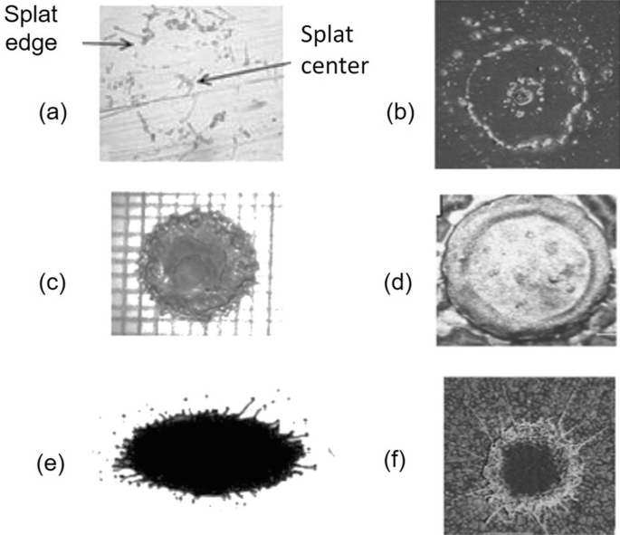
Examples of plasma sprayed splats of different materials on Stainless Steel (SS-304). (a) Alumina on cold SS [Goutier et al. (2011)], (b) Ni on SS pre-oxidized at 150 °C [Dhiman et al. (2007)], (c) Cu on SS [Fukumoto et al. (2011)], (d) alumina on low-carbon steel preheated at 200 °C [Sabiruddina et al. (2011)], (e) alumina on SS preheated at 400 °C [Goutier et al. (2011)], (f) Ni on pre-oxidized SS at 650 °C [Dhiman et al. (2007)]

Roughly splats of the type a and b have a very low contact with the substrate, while those presented in c to e have a much better contact essentially due to substrate preheating over the transition temperature. In these conditions, the molten splat, at least in its central part, has a good contact with the substrate and its cooling depends strongly on its thermal contact resistance with the substrate. For more details, see [Fauchais 2004], [Chandra and Fauchais 2009]. The adhesion of these splats on smooth surfaces preheated over the transition temperature depends also on other parameters and when the conditions c to d presented in Fig. 9.9 are not fulfilled the adhesion on smooth substrates is close to zero.
In the event that the impact angle on the substrate is less, or significantly higher, than the range of normal impact (between 70 and 110°) splats on cold substrates are extensively fingered, especially in the direction of substrate inclination as shown in Fig. 9.10a.[Bianchi et al. (1977), Kang CW, H.W. Ng, and Kang et al (2006), Salimijazi et al. (2007)] have shown, on the other hand, that for stainless steel, copper, and a few other polished substrates (Ra < 0.1 μm), preheated over the transition temperature, splats have an elliptical shape, as shown in Fig. 9.10b when the spray angle, θ, increases from 0° to 75° with the ratio of the major to the minor axes increasing as the spray angle increases.

Impact of alumina plasma sprayed particles (dp = 58 μm, vp = 138 m/s, Tp = 2400 K) onto an inclined ASI-304 SS (impact angle θ =30°) (a) room temperature substrate, (b) substrate preheated over transition temperature [Bianchi et al. (1977)]
For different materials (alumina, zirconia, titania, Al, Ni, Astroloy, and Cu), the relationship between the major and minor axes shows a strong linearity over a wide range of splat sizes. This observation implies that the Elongation Factor EF (ratio between the major and minor axes) does not depend on particle diameter and impact velocity but only on spray angle. The splat thickness increases slightly along the inclined surface and it becomes progressively thicker in the direction of the inclined surface when the spray angle increases. This probably explains why, when the spray angle exceeds a critical value, which depends on the sprayed material and the substrate material, splashing occurs in the inclination direction even on substrates preheated above the transition temperature.
Attention was also given to the impact of the substrate on the crystallographic structure of the coating. Alumina particles were plasma sprayed onto polished (Ra ≈ 0.4 μm) plasma sprayed alumina coatings [Denoirjean et al. (1998)], which were kept at 250 °C before spraying to get rid of adsorbates and condensates. The latter were either as-sprayed (> 99 wt.% γ phase) or preheated at 1373 K at a rate of 5 °C/min, annealed for 6 h and cooled at a rate of 5 °C/min resulting in a 100% α-columnar structure. Some were also preheated to 1873 K at a temperature ramp of 5 °C/min, annealed for 3 h, and cooled at a rate of 5 °C/min resulting in an α-granular structure with grains between 3 and 5 μm. As shown in Fig. 9.11a, on the γ-alumina substrate, alumina splats (γ phase) exhibit a columnar and regular structure ~100–150 nm; the adhesion of the alumina coating (300 μm thick) obtained on this smooth substrate was 35 ± 3 MPa! On the columnar α-alumina substrate, splats (γ phase) form a columnar and irregular structure ~150–300 nm (see Fig. 9.11b); the adhesion of the coating is only 3 ± 1 MPa. On the α-alumina substrate with a granular structure, splats (γ phase) achieve a very irregular structure ~100–400 nm (see Fig. 9.11c), and splats have the tendency to peel off and it is impossible to achieve any coating.

Alumina splats plasma sprayed onto smooth alumina substrates with different microstructures, (a) γ columnar, (b) α columnar, and (c) α granular [Denoirjean et al. (1998)]
[Yang E.-J. et al. (2012)] plasma sprayed alumina particles onto single crystalline alumina substrates (α phase) kept at 900 °C. The growth orientation of alumina splat crystal during rapid solidification was exactly the same as the orientation facets of [001] or [110] of the single crystalline alumina substrate, epitaxial solidification taking place during splat cooling.
2.4.3 Coating Adhesion
-
(a)
Mechanical adhesion takes place when the substrate is roughened, for example, by grit blasting. For the best mechanical adhesion, intuitively the peak heights, characterized by the distance between the highest peak and the deepest undercut (Rt), must be adapted to the mean size of the splats, as illustrated in Fig. 9.12a. The spacing between peaks also plays a key role on the flattening of particles impacting on rough surfaces. The shrinkage of the resulting splats while cooling contributes to the adhesion of the splat to the surface because of the frictional force that develops [Fauchais et al. (1996), Morks et al. (2002), Bahbou and Nylen (2005), Bahbou and Nylen (2007)]. This adhesion depends both on the amplitude of roughness, and on the mean spacing, w, between peaks and valleys. A good mechanical adhesion is achieved when the mean splat diameter, ds, which would be obtained on the same smooth substrate, is about 2 to 3 × Rt. If ds < < Rt, as illustrated in Fig. 9.12b, the adhesion is very poor. It is the same if ds> > Rt, see Fig. 9.12c. However, the flattening liquid drop must also penetrate within the undercuts [Mehdizadeh et al. (2002)]. For that the impact pressure (ρp.vp2) must be larger than the tension force. It results in the following expression, where σp is the liquid drop surface tension.
$$ w>4{\sigma}_p/{\rho}_p{v}_p^2 $$(9.1)

Schematic representation of splat size relative to grit blasted surface peak sizes defined by Rt. (a) Splat size adapted to peak size, (b) too small splat sizes relatively to peak size, and (c) too large splat size relatively to peak sizes
[Bahbou and Nylén (2007)] established that a good correlation exists between the adhesion strength of a NiAl (5 wt%) coatings , on Ti-6Al-4 V substrate, and the root mean square value RΔq of the substrate roughness, which considers both the amplitude and spacing of peaks. The correlation is rather poor when variables such as Ra, Rt or the peak spacing are considered individually. For more details, see [Fauchais et al. (2014) Chap. 12 Surface preparation] and [Fauchais et al. (2014) Chap. 13 Conventional coating formation].
-
(b)
Diffusive adhesion of metals and alloys occurs when the temperature during coating formation is sufficiently high and no oxide layer exists at the substrate surface. In a simplified approach the thermal diffusion distance, dd, is given by:
where t is the time during which the contact occurs at temperature T, and Dth the diffusion coefficient varying as \( {e}^{-{E}_A/ kT} \) where EA is an activation energy, T the absolute temperature, and k the Boltzmann constant. Essentially, good adhesion of a splat/or coating on a substrate can only be assured at sufficiently high substrate temperatures and sufficient contact time the coating material and the substrate. This is conditional, however, to the absence of an oxide layer on the surface of the substrate which in turn depend on the chemical nature of the substrate and that of the ambient atmosphere. Controlled atmosphere or soft vacuum plasma spraying offers means of guaranteeing operation in an inert or reducing atmosphere. Moreover, by operating the plasma torch at reduced ambient pressure in a reverse polarity transferred arc mode for a short period prior to the spray coating operation, it is possible to remove any oxide layer initially present on the surface of the substrate.
-
(c)
Chemical adhesion occurs when the surface atoms of two separate surfaces form ionic, covalent, or hydrogen bonds. It requires that the impacting droplet melts the substrate and a chemical compound of both liquids exists. For example, when Mo particles impact on steel, the melting temperature and effusivity (defined as (ρp.cp.κp)0.5) of the Mo droplet are higher than those of the steel substrate, which melts and reacts to form a chemical compound, MoFe2. Mo particle flattening on a stainless-steel substrate results in splats formed of different pieces as shown in Fig. 9.13a after [Li and Li (2006)]. This type of splashing is due to a localized melting of the substrate surface by the impacting droplet. The melted crater on the substrate surface alters the flow direction of the droplet fluid and tends to form a free liquid jet that detaches from the substrate surface (Fig. 9.13b). Cracking initiated within the Mo splat Fig. 9.13c occurs within it (Fig. 9.13d) due to the restraining of the splat contraction during cooling and also to the low plasticity of the solidified splat material [Li and Li (2006)]. The liquid film observed in Fig. 9.13c and d, mainly resulting from the steel substrate material, promotes the floating of Mo pieces initiated from cracks.

(a) Mo splat on stainless steel (SS) substrate, (b) Schematic diagram of droplet impact inducing substrate melting , (c) Crack initiation in the Mo splat, (d) Displacement by floating of the cracked pieces on low melting point liquid [Li et al. (2006)]
2.4.4 Spray Pattern
The movement of the torch has a significant influence on the heat and mass transfer during the coating process. The structure and final properties of the coating can be improved by adjusting the movement direction and speed profiles of the torch. Thus, the manufacturing of coatings on complex geometries requires the generation of an optimized movement with a defined torch velocity. A bead is obtained (Fig. 9.14a) when translating the torch relatively to the substrate (1-D movement) at a given relative velocity torch-substrate, vr, for example, in the x direction. The bead parameters, its height hb and its width wb at mid-height, depend on the spray process, the torch working conditions, the relative velocity torch-substrate vr, the powder mass flow rate \( {\dot{m}}_p \), the particle size distribution, the deposition efficiency ηd, the torch nozzle internal diameter dn, the injection conditions, and the spray distance.

Schematic representation of the coating formation on a flat substrate (a) spray-bead, (b) typical spray pattern
In fact, a Gaussian shape is in good agreement with the distribution of hot particles. In the bead wings, particles impact with an angle and lower velocities and temperatures resulting in a more porous area with a poorer contact between splats. Also, in the wings of the bead, frequently particles appear which are not well exposed to the hot jet but are sufficiently heated to stick to the bead wing. Moreover, these particles, at least the metallic ones, are easily oxidized in-flight and they may form the major source of oxide inclusions in sprayed coatings, and thus create defects. The coating is achieved for each successive layer by moving the torch as shown in Fig. 9.14b. Once the first layer is achieved the next one is built following the same process with every pass overlapping previous beads, deposited in the x direction (Fig. 9.11a), the next bead being deposited at a distance d in the y direction and its thickness depends on the overlapping ratio. For a plane substrate, the distance d between successive beads in the y direction is calculated as the bead width at mid-height wb generally multiplied by a given number, generally called overlapping ratio, f, (typically 0.33, 0.5, 1.0, 2.0, 3.0). The choice of the beads overlapping ratio depends on their thickness and the acceptable level of surface undulation.
When spraying off-normal angles , there is always a risk of having particles intercepted by the bead rebounding and splashing on the other side of it, as shown in Fig. 9.15. The adhesion of the splashed material being very poor, it will be the same with the next bead deposited on top of it.

Splashed material from inclined spraying where the bead intercepts part of the impacting particles
3 Controlled Atmosphere Plasma Spraying
3.1 Ambient Gas Entrainment in DC Plasma Jets
As discussed in “Chapter 8, DC Plasma Spraying –Fundamentals” DC plasma jets working in air are known for their high-energy density and high plasma temperature (above 12,000 K) and velocities (in the hundreds of m/s) with steep temperature and velocity gradients. As the plasma jets immerge into a stagnant ambient atmosphere, a strong shear layer develops in the interface between the jet and the ambient gas. The structure of such a flow has been the subject of intense studies in the 1980s and 1990s due to its impact on the overall jet behavior and the resulting flow and temperature fields [Pfender et al. (1991)], [Russ et al. (1994)]. Based on Schlieren photographs, emission spectroscopy, and enthalpy probe concentration [Pfender et al. (1991)] concluded that the large velocity difference between the jet and the ambient atmosphere causes rolling up of the flow around the nozzle exit into the ring vortex which is pulled downstream by the flow, allowing the process to repeat itself again at the nozzle exit. Adjacently formed vortex rings at the outer edge of the jet have the tendency to coalesce, forming large vortices. As schematically represented of the flow pattern given in Fig. 9.16a, and supported by the Schlieren image of a DC plasma jet in ambient air, Fig. 9.16b, the distorted vortex rings start entangling themselves with the adjacent rings, finally resulting in total breakdown of the vortex structure into large-scale eddies and the onset of turbulent flow. This process results in the first large-scale engulfment of the ambient gas into the jet flow. Some entrainment also takes place during the roll-up process of the jet shear layer. The eddies of cold gas traveling in the axial direction at lower velocities than the flow continuously break down into smaller eddies, while diffusion takes place on the molecular level at all eddy boundaries. The extent of the impact of ambient gas entrainment on the temperature fields of a DC plasma jet is demonstrated in Fig. 9.17 after [Roumilhac et al (1990)] showing the temperature isocontours for a pure argon DC plasma jet in an open discharge in an ambient argon atmosphere (Fig. 9.17a), in a nitrogen atmosphere (Fig. 9.17b) and in air (Fig. 9.17c). These show a clear quenching effect resulting from the engulfment of nitrogen or air into the argon plasma flow. The effect is quantitatively noticeable in Fig. 9.18 giving the profile of the plasma temperature and the molar fraction of entrained air in the axial direction along the centerline of a DC pure argon plasma jet in an open discharge into ambient air. The results show that the mole fraction of air on the centerline of the jet reaches 50% only 34 mm downstream of the nozzle exit of the jet.

(a) Schematic representation of the main regions of DC plasma jet showing the rolling of the flow around the nozzle exit, cold eddy engulfment, and breakdown followed by turbulent flow generation, (b) Schlieren image of a DC plasma jet in ambient air [Pfender et al. (1991)]

Effect of the ambient gas entrainment on the temperature contours of an argon plasma jet, with air showing the strongest quench effect. (a) Argon ambient gas. (b) Nitrogen. (c) Air, derived from data published by [Roumihac et al. (1990)]

Axial distributions of enthalpy-probe measurements of plasma temperatures, volume fraction of entrained air in the plasma jet, and CARS-temperatures of the entrained oxygen showing the low temperatures of the entrained oxygen [Finke et al. (2003)] (reproduced with kind permission of Elsevier)
Other than the above discussed impact of ambient air entrainment on the temperature field in the plasma jet, the abundance of oxygen mixed with the plasma flow can have a detrimental effect of the chemistry of the material being sprayed especially when dealing with pure metals, alloys, or non-oxide ceramics (carbides, nitrides...). The air entrainment could result in these cases in the in-flight oxidation of sprayed material. [Syed et al. (2006)] investigated the in-flight oxidation of stainless-steel particles in the plasma spray jets in an open discharge mode. Two types of 316 L austenitic stainless-steel particles were sprayed by a DC plasma gun with a 7 mm anode nozzle i.d. varying gun parameters and surrounding gases composition. Electron micrographs given in Fig. 9.19 show the surface morphology and cross-sections of the powder used. The first (Fig. 9.19a, b) was a gas-atomized TY316L with a particle size in the range (63–50 μm) from Techphy H.T.M., France. The second, coarser powder (Fig. 9.19c, d), was a water-atomized feedstock referred to as 41C (106–45 μm) from Sulzer Metco, USA. Following the injection of each of these two powders in the plasma jet in an open discharge mode in air, the treated powder was collected and characterized to establish relationship between spray parameters and particle oxidation. The results given in Fig. 9.20 show that, besides diffusion-based oxidation, convective oxidation in the particles can also occur within the plasma jet core if plasma to molten particle kinematic viscosities ratio is superior to 55 and the Reynolds number (Re) of the flow relative to the particle/droplet is more than 20. In these conditions, the oxide formed, or oxygen dissolved at the surface of the liquid droplet, can be swept into its interior forming isolated oxide nodules. Fresh liquid metal is transported from interior toward particle surface.

(a) Electron micrographs of feedstock 316 L stainless steel particles, (b) cross section of sprayed particles, (c) Sulzer-Metco powder feedstock, (d) cross section [Syed et al. (2006)]

Electron micrographs images of the plasma treated particles (a, b) of polished cross sections showing oxide nodules (c) oxide cap [Syed et al. (2006)]
The oxidation rates were estimated to be higher compared to diffusion-based oxidation which is the dominant phenomenon in the plasma jet plume in the absence of convective oxidation. Spray parameters leading to higher kinematic viscosities ratio and Re, such as increasing arc current, hydrogen content in the plasma forming gases, or decreasing sprayed particle size range, resulted in enhanced convective oxidation in the plasma core. The diffusion-based oxidation of particles in the plasma jet plume can be principally controlled by their size (specific surface area), temperature and velocity (dwell time), and the molar fraction of oxidizing and reducing species in the plasma jet. While investigating the influence of the atmosphere of plasma jet on the in-flight particle oxidation, it was found that the surface area of the oxide nodules and the mass percentage of total oxygen in collected particles followed a parabolic and linear relationship with the partial pressure of oxygen, pO2 in the surrounding atmosphere. Keeping surrounding pO2 at 0.1 and altering N2 and Ar content resulted in higher oxygen content in particles sprayed in Ar-rich surrounding, whereas no distinct difference in oxide nodules surface area was reported. [Syed et al. (2006)] studied systematically in-flight reactions especially those resulting in metastable oxides. Oxide nodules with mixed oxide of Cr, Fe, Mn, and Si as cations were detected. Spinel type Fe3-xCrxO4 form was the observed phase with x being between 1.5 and 1.9. No corundum type oxide phase was detected.
It should be pointed out that other than the in-flight particle oxidation during the spray process, the presence of entrained air in the plasma plume would also result in the oxidation of the substrate surface and coating, especially between successive passes which would lead to the decrease of the adhesion/cohesion of coatings and hinder diffusion phenomena at the coating-substrate interface.
3.2 Systems and Operating Conditions
While the use of a gas shroud as described earlier in Chap. 8 “DC Plasma Spraying, Fundamentals” offers means of reducing the entrainment of ambient air/oxygen into the plasma jet and consequently the chances of in-flight oxidation of the sprayed particles, the spraying of oxidation sensitive materials in a controlled atmosphere plasma spraying (CAPS) chamber has been widely accepted as more effective and secure way to protect the contamination of the coating with ambient gas species. (CAPS) developed in the 1960s, uses essentially vacuum-tight chambers with a vacuum pump, for the initial evaluation of the chamber, before backfilling it with an inert gas, usually argon, to atmospheric pressure or higher. The oxygen content in an argon atmosphere can be lower than 7 ppm if a liquid argon source is used [Freslon A. (1995)]. As shown earlier plasma jets in argon atmosphere are broader and longer by a factor 1.5 to 2 compared to the plasma jet in air [Roumilhac (1990)]. Nitrogen atmosphere results in an intermediate plasma jet (Fig. 9.17). If the spray chamber is big enough ≈10 m3 there is no need to water-cool its walls.
CAPS is normally operated at pressures in the range of 70 to 300 kPa for the spraying of materials which are very sensitive to oxidation such as carbides, borides, and refractory metals. For example, to spray carbides the jet in argon atmosphere must be longer than the jet obtained in air. Few tests have been performed using chambers at pressures over 300 kPa [Jäger et al. (1992)]. The plasma jets are shorter in this case compared to that at atmospheric pressure, and electrode erosion becomes more important due to the increased radiation from the plasma column. The increase of the ambient pressure also results in the increase of arc voltage since the arc column constricts and its temperature rises, resulting in higher losses to which the arc responds by an increase of the electric field strength (arc voltage). As the heat losses increase, the specific enthalpy of plasma jet shows a slight drop. At chamber pressure below 300 kPa specific mass, viscosity and thermal conductivity of Ar plasma jet are higher, which is necessary for the spraying of carbides. It should be pointed out that even when using CAPS, the chemistry of the coating remains sensitive to that of the composition of the plasma gas and/or the ambient atmosphere. For example, when spraying reactive metals such as titanium with Ar-N2 plasma-forming gas, in controlled argon or nitrogen atmosphere chamber, at different pressures, the nitrogen content of the coating in the form of TiN can be significant: the coating content (wt.%) is 2.8 with a chamber pressure of 20 kPa against 12.4 at 119 kPa [Jäger et al. (1992)]. [Guipont et al. (2002), Espanol et al. 2002, Guipont et al. (2010)] have sprayed hydroxyapatite with argon plasma working in argon atmosphere at pressure up to 0.3 MPa. They have shown that the decomposition level can be tailored without using N2or H2. Coatings present highly soluble as well as less soluble (crystalline) characteristics. The nature of the ceramic composite with multiphases can be adjusted through the chamber pressure. Alumina coatings sprayed in Ar atmosphere at different pressures exceeding atmospheric pressure have also been reported [Ma et al. (2002)]. Another advantage is the temperature regulation of both substrate and coating (up to 1000 °C if the treated material can sustain it) resulting in better adhesion. The promoted diffusion results in better densification of coatings. The absence of oxides and the better adhesion can result in higher coating thickness, superior hardness.
[Leylavergne et al. (1998)] compared plasma-sprayed coatings produced in argon or nitrogen atmosphere. The choice between argon and nitrogen atmosphere also depends on cost considerations, nitrogen being 25 to 30% cheaper than argon! They showed that in controlled atmosphere plasma spray process, the use of a nitrogen instead of an argon atmosphere results in coatings with comparable properties. The nitrogen content of the niobium and titanium carbide coatings analyzed in this paper was at most 1%. This result was confirmed with other ceramic and metal coatings. The diffusion of nitrogen seemed to occur in-flight in the molten droplets, with the cryogenic cooling of the substrate by liquid nitrogen jets preventing the reactions after impact of the droplets onto the substrate. Gas flow fields were computed in nitrogen and argon atmospheres. The predictions confirm the small differences observed in coating properties. Under the conditions of the present study, the replacement of argon by nitrogen as an inert atmosphere seems feasible, thus reducing process operating costs by approximately 30%.
In a study of the tribological behavior of Al2O3 coatings on AISI 316 stainless steel, [Sarafoglou et al. (2007)] operated a CAPS process at higher pressure in the 100 and 400 kPa range, referred to as High Pressure Plasma Spraying (HPPS). The results indicate that plasma composition, through its higher heat capacity, does influence the heat transfer to particles, and, consequently, their flattening and densification process, which govern coating properties. It was revealed that tribological behavior of coatings was also influenced by the applied spraying method. However, HPPS coatings led to worst wear behavior. In general, properties, such as microstructure, microhardness, coefficient of friction, and wear resistance depended on the processing conditions such as pressure and composition of the spraying chamber atmosphere. The dominant wear mechanism was that of abrasion for all coatings and conditions of wear tests, and that of adhesion for the antagonistic material.
4 Vacuum Plasma Spraying
4.1 Basic Concepts
Vacuum Plasma Spraying (VPS) also referred to as Low Pressure Plasma Spraying (LPPS) was developed in 1974 by Müehlberger (Electro-Plasma Inc., now Öerlikon Metco Inc.) [Muehlberger E. (1988), Meyer and Hawley (1991)]. It is a process carried out under soft vacuum conditions in a controlled atmosphere chamber at absolute pressures in the range of 5 to 70 kPa allowing for the coating of small to medium-sized parts of complex shapes with high-density coatings of metals and alloys including refractory metals. Compared to APS, its principal advantages are:
-
Prevents in-flight and post-deposition oxidation of the spray powders insuring an oxide-free deposit.
-
Substrate can be maintained at high temperatures (up to 950 °C for superalloys) without oxidation. Such temperatures promote inter-diffusion, thus enhancing the coating adhesion,
-
High velocity plasma jet (2000 to 3000 m/s) giving rise to higher particle velocities compared to APS (800 to 900 m/s for alumina and of 450 to 650 m/s for YSZ).
-
Lower density gradients between the plasma jet and the surroundings atmosphere result in more stable jets and with less cold gas entrainment providing a more uniform particle heating and acceleration as well as less divergence of the particle trajectories.
-
Reduced heat transfer rates to particles largely compensated by longer jets and increased residence time in the plasma; reduced heating rates also result in less superheating of the particle surface and lower temperature differences between particle surface and its center.
The principal limitation of VPS is the size of the parts that can be coated and the melting temperature of the material to be sprayed which excludes ceramic materials particularly non-oxide ceramics with melting temperatures above 3000 K. The high capital investment needed for such installations also imposes an important limitation on the wider used of the technology.
As shown in Fig. 9.21, VPS is carried out in large vacuum chamber with volumes of a few m3 up to 10–20 m3, typically 1.5 to 2.5 m in diameter by 3 to 4 m long, which houses the substrate, often on a carousel holding more than one part to be coated, a DC plasma torch, and a robotic torch manipulator. The chamber is normally water-cooled with a large access door for ease of servicing, placing the parts to be coated on the carousel substrate holder and retrieving them at the end of the coating cycle. The gas exit port of the chamber is connected to an efficient dust/fume collection filter followed by a high-volume pumping station capable of the initial evacuation of the chamber below 1 kPa in a reasonable time (a few minutes) and to maintain the chamber pressure during the spraying cycle under soft vacuum (5 > p > 70 kPa). It is to be noted that under such pressure range of operation, the torch nozzle must be adapted for supersonic jet velocities to reduce or avoid the formation of diamond shock waves in the jet.

Schematic representation of a low-pressure plasma spray chamber. (Courtesy of Emil Pfender)
Torch operation is similar to that of APS torches, that is, with similar arc currents, plasma gas selections and flow rates, power levels, and powder flow rates. The torch-to-substrate distance is longer than normally used in APS, typically in the range of 250 and 500 mm. At the start of each operation cycle, the chamber is pumped down to a pressure of a few Pascal, and then backfilled with high purity argon to the desired operating pressure. Depending on the lowest absolute pressure that can be achieved by the pumping system, and the sensitivity to oxidation of the material to be sprayed, the cycle of chamber evacuation and its refilling with pure argon may need to be repeated more than once in order to bring down the residual oxygen level in the chamber to an acceptable level, typically in the range of a few ppm O2.
Prior to the initiation of the spraying cycle and depending on the material to be sprayed and the substrate properties, a substrate surface cleaning and preheating step might be necessary. This is carried out using the plasma torch in a reversed-polarity transferred-arc mode as shown in Fig. 9.22a, in which a low-current arc is established between the substrate and the plasma torch with the substrate acting as cathode and the torch as anode. The substrate surface cleaning process, typically carried out with a chamber pressure of 2 kPa and an arc current between 20 and 120 A, results in the evaporation of impurities, in particular of oxides, in a timeframe of a few minutes [Itoh et al. (1990)]. Following the substrate surface cleaning step, substrate preheating to sufficiently high temperature to promote coating adhesion is possible by switching the transferred arc to a straight-polarity mode, as shown in Fig. 9.22b, with the substrate acting as anode and the torch as cathode. The chamber pressure is increased to 6 kPa, which is typically the working spraying pressure, and the arc current is kept between 50 and 150 A. In VPS, the substrate can be maintained at high temperatures (up to 950 °C for superalloys) without oxidation. Such temperatures promote inter-diffusion, thus enhancing significantly the coating adhesion.

Principle of the transferred arc in VPS (a) reverse polarity, substrate as cathode for the surface cleaning step (b) straight polarity, substrate as anode for the substrate preheating step
With the ignition of the plasma torch for spraying operation, the plasma jet becomes increasingly longer and wider as the pressure decreases because the cooling through the entrained air is avoided [Roumilhac et al. (1990)]. Modeling results of axial temperature distributions along the centerline of an argon DC plasma jet issuing into an argon environment at different pressures are given in Fig. 9.23. These show an increasingly longer plasma jet, and the much slower temperature decay with the decrease of the chamber pressures. Figure 9.24 shows corresponding axial velocity distributions for a low power argon plasma jet (8 kW) with 11.6 g/min argon flow in an 8 mm diameter anode-nozzle and three different chamber pressures. The strong increase in the plasma velocity is noticeable compared to APS operation, even with pure argon. The lower axial temperature and velocity gradients are due to the lower large-scale turbulence and less cold gas entrainment, a consequence of the smaller density gradients resulting in less turbulent shear layers. The lower densities result, however, in lower electron-ion recombination rates, and deviations from composition and Local Thermodynamic Equilibrium (LTE). The effect of going to very low pressures on the plasma jet and particle properties has been shown by [Refke et al. (2003)] using an experimental vacuum chamber and a Sulzer-Metco O3CP torch, a set-up that has the capability to be operated down to 0.1 kPa (1.0 mbar) with up to 150 slm of total gas flow rate. The process, identified as Ultra Low-Pressure Plasma Spraying (ULPPS), is discussed in the next section.

Effect of chamber pressure on the axial temperature profile along the centerline of DC pure argon plasma jet. (Courtesy of Emil Pfender)

Axial velocity profiles along the centerline of DC pure argon plasma jet at different chamber pressure. (Courtesy of Emil Pfender)
4.2 Torch Nozzle Design and Gas Dynamics
For compressible nozzle flows reaching supersonic speeds inside the nozzle, shock diamonds are usually observed in the plasma jet (see schematic in Fig. 9.25). These occur when the pressure inside the jet is different from the surrounding atmosphere leading to sudden velocity drop and the creation of shock waves. The jet is identified as “over-expanded” when the pressure inside the jet is lower than the ambient pressure in the chamber, and “under-expanded” with a jet pressure higher than the ambient pressure. As a consequence, through the interaction with the environment the jet is compressed or expanded, but an over-compensation may occur resulting in another under-expansion/over-expansion of the flow. A complex flow structure evolves with shock waves starting at the nozzle exit being reflected at the discontinuity between jet and environment, and these reflected shockwaves create the shock diamonds. The more shock diamonds and the clearer they are visible, the worse the fluid dynamic condition. The use of a properly designed Laval nozzle either as part of the anode or as an attachment to the anode can significantly improve the results by avoiding the shock structures immediately downstream of the anode nozzle exit [Meyer and Hawley (1988)]. A schematic of a torch with a Laval nozzle attachment is shown in Fig. 9.26 to improve the problem cited above [Meyer and Hawley (1988)]. The Laval nozzle attachment offers an increase of particle velocities by 30% to 50% and particle trajectories parallel to the torch axis [Meyer and Hawley (1988), Henne et al. (1993)], resulting in a higher deposition efficiency [Rahmane et al. (1998)].

Schematic illustration of shock diamond as consequence of inadequate equilibration between pressures in the jet and in the surroundings

Schematic of torch nozzle with Laval attachment for improved supersonic flow structure [Mayr and Henne (1988)]. (Reproduced with kind permission of Sulzer Metco AG, Switzerland)
With a Laval-type nozzle design (Fig. 9.26) the jet will lengthen and enlarges in soft vacuum, as shown in Fig. 9.27. At 95 kPa the jet is only close to 60 mm long, at 5 kPa its length reaches 400 mm, and if the pressure is reduced down to 0.1 kPa the jet length can be more than 1200 mm and up to 200 mm in diameter.

Images of plasma jets in a controlled-atmosphere chamber expanding at different pressures (a) 95 kPa (APS), (b) 5 kPa (VPS), (c) 0.1 kPa (ULPPS) and deposition process [von Niessen and Gindrat (2011)]
4.3 Coating Microstructure
In the following paragraph, a few examples of coatings achieved with VPS (also LPPS) are presented:
NiCoCrAlY coating obtained by [Scrivani et al. (2003)] with a Central Injection APS torch, HVOF torch, and VPS system showed the VPS coatings to be significantly superior with lowest porosity, lower unmelt density, and practically no oxide formation. This is illustrated in Fig. 9.28 showing significant variations in the coating microstructures before thermal treatment, the denser structure being that of VPS (Fig. 9.28c). Axial plasma sprayed coatings show higher amounts of un-melted particles with respect to other traditional technologies. HVOF coating shows some un-melted particles and this could be expected because the HVOF flame is colder than the plasma jet. Un-melted particles could not be observed in the coatings produced by VPS. VPS produces coatings that are quite completely oxide-free.

Microstructure of CoNiCrAlY alloy coatings obtained by different thermal spray technologies (a) Central injection APS (b) HVOF (c). VPS [Scrivani et al. (2003)]
[McKechnie et al. (1994)] reported that VPS forming has been developed and characterized for near-net-shape fabrication of aerospace components . Applications require VPS forming of structural materials in both monolithic form (i.e., free-standing shapes) and as integral parts of complex components (e.g., liner for a rocket engine combustor). In these applications the material deposited on both the inside and the outside of large and small components must meet strict quality requirements . They used NARIoy-Z, which is a copper-base alloy with a nominal composition of Cu-3.0Ag-0.5Zr and high thermal conductivity. It is used in the combustion chamber liner of the Space Shuttle main engine and is the baseline material for current VPS forming development. Authors discussed metallurgical and processing comparisons between depositing material on inside and outside surfaces of symmetrical shapes. Specific examples of material properties (e.g., grain structure, hardness, and tensile properties) and process parameters (e.g., standoff distance and gun design) are presented in terms of the fabrication of large rocket engine combustion chambers (Fig. 9.29).

Vacuum plasma spray forming of NARIoy-Z on the outside of a combustion chamber mandrel [McKechnie et al. (1994)]
Microstructure of silicon coating prepared by [Niu et al. (2009)] using VPS technology is given in Fig. 9.30. This shows compact dense silicon coating with no identifiable areas of silicon oxide. Small ball-like particles of sizes of less than 1 μm was found on the surface and in the coatings, which seems to result from splash debris. The porosity was low and composed of pores with spherical and linear shapes. The coating exhibited typical two-layer microstructure in flattened splats which had equiaxed nanometer grains and overlying columnar grains in the longitudinal section.

Cross-sectional micrograph of VPS-Si coatings [Niu et al. (2009)]
[Niu et al. (2013)] reported a study of MoSi2 coating prepared by the VPS technology. These exhibited a lamellar and dense microstructure, which was composed of grains with irregular shapes and different sizes of 0.1–0.2 μm. It was composed mainly of tetragonal and hexagonal MoSi2 phases and a small amount of tetragonal Mo5Si3 phase. TEM observation confirmed that Mo5Si3 was randomly distributed in the matrix of MoSi2. After being exposed to air at 1300 and 1500 °C for 6 h, a dense and thin film (<10 μm) of silicon oxide was formed on the surface of the MoSi2 coating, providing excellent protection for the coating. Applying the heat treatment at 1700 °C for 6 h resulted, however, in the formation of a relatively thick layer (20–30 μm) of Mo5Si3 formed under the silicon oxide film indicating the oxidation of the MoSi2 coating.
[Salimijazi et al. (2005a, b)] reported studies of the Vacuum Plasma Spraying of Ti-6Al-4V alloys and B4C in an attempt to produce near net-shaped structural parts of layered composite materials for light weight ballistic protection applications. The work was undertaken in two steps, the first dealing with the deposition of Ti-6Al-4V alloys [Salimijazi et al. (2005a)] on copper, as a dummy substrate. Detailed microstructural, chemical composition analysis of sprayed material was made. The observed chemistry and microstructure of the coating reflected the conditions under which the coating was formed and the phase equilibria in the Ti-alloy system. The porosity of the deposit was in the range of 3 to 5%. Slight decrease in the Al content and an increase in the amount of oxygen and hydrogen were found relative to the starting powder. The latter was attributed respectively to oxygen leakage into the vacuum deposition chamber and the use of hydrogen in the plasma forming gas. As with any structural material, attention was also given to metallurgical considerations such as grain size, phase composition, and phase distributions. The as-deposited material is ≥90 % α′martensite that is present in the form of fine lathes on the order of 500 nm in width surrounded by residual β− phase. SEM micrographs of an etched Ti-6Al-4V deposit given in Fig 9.31a show a columnar grain structure within the central core of the splat which are oriented in the direction of heat transfer to the substrate, or prior splat. Optical micrographs of the etched cross section of the deposit given in Fig 9.31a show the presence of some unmolten and partially molten particles, with isolated larger porosities detectable in the unetched micrograph given in Fig 9.31c.

Cross section micrographs of VPS deposited Ti-6Al-4 V alloy (a) SEM micrograph (b) etched optical micrograph (c) unetched optical micrograph [Salimijazi et al. (2005a)]
The second part of the study [Salimijazi et al. (2005b)] was dedicated to the VPS deposition of B4C on Ti-6Al-4V substrate with a coating thickness of 300 to 600 μm. The microstructure of a polished section of the B4C deposit is given in Fig. 9.32a, b which shows the splat morphology and the pore structure in the deposit. According to [Salimijazi et al. (2005b)] the rounded pores could be caused by gas entrapment during the deposition while angular edged pores were attributed to loss of solid particles or fragments. The B4C deposit was also subjected to surface hardness measurements using both Knoop and Vickers indenters. Knoop hardness tests were performed with the long axis of the Knoop indenter both parallel and perpendicular to the splat spread direction. The applied load for Knoop hardness measurements was 500 g. The as-sprayed B4C has an average hardness of 1236 ± 140 KH parallel to the splats and 1583 ± 103 KH in the perpendicular orientation. Some cracks along the splat boundaries oriented in the direction of the large diagonal of the Knoop indenter can be observed (Fig. 9.32c).

Micrograph of polished cross section of the VPS B4C deposit (a) optical micrograph (b) SEM micrograph (c) micrograph showing cracks propagation around the microhardness indentation area [Salimijazi et al. (2005b)]
A study for the optimization of the operating conditions for the VPS deposition of boron carbide (B4C) was reported by [Lin Chun-Ming (2012)]. According to results obtained by a Taguchi design method a deposit porosity of 8.5% was obtained using the following near optimal operating conditions: chamber pressure of 65 kPa, current 680 A, plasma gas flow rate [45 slm (Ar) +13.5 slm (H2)], and spraying distance of 150 mm. Further optimization of the spraying parameters by [Lin Chun-Ming (2012)] involved the combination of Taguchi design method with a neutral network / Generic Algorithm, (GA), allowed for the reduction of the porosity level of the deposit to 5.6% using revised operating conditions: Chamber pressure of 66 kPa, current 680 A, plasma gas flow rate [39.7 slm (Ar) +12.5 slm (H2)], and spraying distance of 236 mm.
[Liu et al. (2017)] showed that coating quality is affected by arc and plume instabilities during plasma spraying. In closed chamber plasma spraying, gradual drift is one of the intermediate instabilities, which is mainly due to the electrode erosion. Their work focuses on the source of the gradual drift of the plasma jet and the influence on coating quality. The variation in the plasma jet was observed by a particle flux image device based on a CCD camera. The optical spectrum of the plasma plume was measured and analyzed through an optical spectrometer. The results indicated that the addition of hydrogen to plasma gas induced the change in the plasma jet length and width with changing rates depending on the chamber state and the ventilation power. With poor ventilation, the intensity of Hα emission was found to become gradually stronger while Hβ and Hγ were found to become weaker. On closing the chamber and retaining enough ventilation power, it was observed that the ambient gas slowly turned red. Simultaneously, the coating weight and thickness were slightly decreased. Meanwhile the porosity ratio was obviously increased. The red ambient gas has been proved to be able to acidify the city water with pH value decreased from 7 to 1–3. Without hydrogen, the plasma jet was found to be stable without reddening and variation, but the plasma enthalpy was unfortunately low.
An interesting study reported by [Zhang et al. (2006)] compared the performance of APS and VPS technologies for the manufacture of the electrolyte materials for Solid Oxide Fuel Cells (SOFC). The study was carried out using two commercially available yttria stabilized ZrO2 (YSZ) 8 mol% Y2O3 powders:
-
The first called “YSZ1” was a fused-crushed powder (Plasmatex, Sulzer-Metco, Winterthur, Switzerland) with particle size range 5 to 26 μm.
-
The second called “YSZ2” was an agglomerated powder containing nanoscale substructure of 25 nm (TZ8Y, TOSOH, Tokyo, Japan) with particle size range 20 to 116 μm.
Coating layers with these two powders were deposited by Vacuum Plasma Spraying (VPS) and atmospheric plasma spraying (APS) to compare the impact of spray methods and particle morphology-size/manufacturer on the electrical conductivity and gas permeability of the coating obtained. The microstructure of YSZ coating was characterized using scanning electron microscopy and X-ray diffraction analysis . The results showed that for each of the two powders, the gas permeability of the coating made using VPS is lower than that obtained using APS. Different results were obtained, however, with different powders, with the gas permeability of the coating made by fused-crushed powder (YSZ1) generally one order of magnitude lower than those produced by the agglomerated powder (YSZ2). The electrical conductivity of the coatings, measured by potentiostat/galvanostat based on three-electrode assembly approach, using fused-crushed powders of small particle size, showed that coating deposited by VPS was 0.043 S/cm, at 1000 °C, which is about 20% higher than that of APS with the same powder.
5 Ultra Low-Pressure Plasma Spraying
5.1 Basic Concept and Gas Dynamics
Ultra-Low-Pressure Plasma Spray (ULPPS), also identified as Very Low Pressure Plasma Spraying (VLPPS), Plasma Spray-Physical Vapor Deposition (PS-PVD) and referred to by Sulzer-Metco as Low Pressure Plasma Spraying-Thin Film (LPPS®-TF) is a relatively new technology that bridges the gap between conventional VPS spraying processes in which the coating is formed through the building up of successive splats on the surface of the substrate, and Physical Vapor Deposition (PVD) processes in which the coating is formed through the deposition of the coating material from the vapor phase at lower temperatures at relatively low deposition rates. In fact, ULPPS is a process developed in direct competition to EB-PVD, for the production of ceramic TBC coatings with equivalent quality as EB-PVD technology, at considerably higher deposition rates and lower cost. The two technologies, ULPPS and EB-PVD, differs essentially in the way the precursor is transformed into the vapor phase with ULPPS based on the in-flight heating and evaporation of the precursor in powder form using the plasma jet, while EB-PVD makes use of an Electron Beam for the precursor evaporation form a solid target or powder. This difference has a significant impact on their respective operating pressure and the deposition rates associated with each of the two technologies, with the ULPPS process operating at pressures (< 200 Pa) with deposition rates in the range of μm/s, in contrast to the Electron Beam technology which required considerably lower operating pressures (<5 Pa), has lower deposition rates in the 0.1 to 100 μm/min range, and significantly higher investment cost.
[Niessen and [von Niessen and Gindrat (2011)], Hospach et al. (2011), Mauer et al. (2010, 2013, 2015), and Mauer (2014), 2019] were among the first who worked on the Ultra-Low-Pressure Plasma Spray (ULPPS), which they achieved using a modified single cathode vacuum plasma gun, the Sulzer Metco O3CP, which allows for the use of a high gas flow, up to 200 slm, and torch current up to 3000 A (180 kW). The gun can be run with either a two- or fourfold internal powder injection. Pre-heating and cleaning of the substrate can be performed by the plasma itself or by means of an integrated transferred arc processing to optimize the coating adhesion. The combination of a high-energy plasma gun and a low-pressure environment enables achieving a predefined evaporation of the injected powder material and the controlled formation of dense thin film coatings by vapor phase deposition. As shown in Fig. 9.33, [Sulzer-Metco bulletin (2008)] the plasma jet is typically more than 2 m long, with a jet diameter of 200 to 400 mm for a plasma torch power of 180 kW. A photograph of such a ULPPS installation at the Forschungszentrum J \( \ddot{u} \) lich GmbH, Institut f \( \ddot{u} \) r Energieforschung J \( \ddot{u} \) lich, Germany, which is an upgraded Sulzer Metco LPPS system, is given in Fig. 9.34. [Mauer et al. 2010].

Images of the plasma jets in the LPPS®-TF process, chamber pressure 200 Pa (2 mbar), plasma Jet length 2 m, Jet diameter 200–400 mm, torch power up to 180 kW with 4 powder injectors. [image and info courtesy of \( \ddot{O} \) relikon-Metco corporation]

New LPPS-TF facility at the Institute of Energy Research Germany (IEF-1), Forschungszentrum Jülich [Mauer et al. (2010)]
At this pressure, the plasma jet interaction with the surrounding atmosphere is very weak. The plasma velocity is almost constant over a large distance from the nozzle exit, the collision frequency is distinctly reduced, and the mean free path is significantly increased. As a consequence, the specific enthalpy of the plasma is substantially high, though at low density. These particular plasma characteristics offer enhanced possibilities to spray dense, thin film, ceramics coatings compared to conventional processes which operate in the pressure range between 5 and 20 kPa.
An early diagnostic study was reported by [Refke et al. (2003)] for an Ar/H2 [100 slm (Ar) + 3 slm (H2)] plasma generated using a Sulzer-Metco-O3P torch operated at a current of 1500 A and absolute pressure of 150 to 200 Pa and 1 kPa in which fin YSZ powder was injected. Measurements were made, using enthalpy probe techniques, of the plasma velocity and temperature profiles in the radial direction at axial location 775 mm from the torch nozzle exit. DPV-2000 system was used for the measurement of the corresponding in-flight particle velocity and temperature at an axial location of 975 mm from the torch nozzle exit. Typical results given in Fig. 9.34a, b are for the plasma and particle velocity profiles in the radial direction at absolute chamber pressures of 200 Pa and 2.0 kPa for the plasma velocity, 150 Pa and 1 kPa for the particle velocities. As expected, the reduction of the pressure from 1 kPa to 200 Pa gives rise to a significant increase of the maximum plasma velocity on the centerline of the flow from 1100 m/s to 2800 m/s. The effect of pressure on the corresponding particle velocities is relatively small. The corresponding radial profiles for the plasma and in-flight particle temperature are given in Fig. 9.35c, d. The effect of the pressure on the temperature of the plasma is less pronounced with the maximum flow temperature increasing from 6500 K to almost 9000 K. The central part of the plasma jet flow is relatively uniform over a radius of about 40 mm beyond which the temperature of the plasma drops rather steeply. The decrease in chamber pressure from 1 kPa to 150 Pa has only a small impact on the particle temperature. The results also show relatively uniform particle velocity and temperature over a large central region of the flow with a radius of more than 100 mm.

Radial profiles of the velocity and temperature fields in an Ar/H2 [100 slm (Ar) +3 slm(H2)] plasma jet at 1500 A in the presence of YSZ particle injection (a) plasma velocity (b) particle velocity (c) plasma temperature and (d) in-flight particle temperature. Results given in (a&c) z = 775 mm (b&d) z = 975 mm from nozzle exit [Refke et al. (2003)]. (Reprinted with permission of ASM International. All rights reserved)
Details of the O3CP torch nozzle design used by Refke et al. (2003) is given in Fig. 9.36. [Mauer (2014)] points out that while the plasma velocity at the critical nozzle cross section cannot exceed the local speed of sound (Mach number Ma = 1), the jet becomes supersonic (Ma > 1) when subsequently passing through the nozzle expansion section. As the flow is faster than the pressure waves traveling in the plasma at the local speed of sound, no information on the chamber pressure is carried inside the nozzle. This means that the plasma gas can exit the nozzle at a pressure which is different from the chamber pressure. Since the chamber pressure under PS-PVD conditions is lower than the pressure in the exiting jet, it becomes under-expanded, that is, it tends to expand immediately after the nozzle to accommodate to the chamber pressure. Having reached pressure equilibrium, the free-flowing jet is highly laminar, and no turbulent transition occurs along the spray distance to the substrate.

In his study of the plasma characteristics and the interaction between the plasma and the coating powder precursor, [Mauer (2014); He et al. (2017)] conclude that:
-
Plasma characteristics and torch gas dynamics in the ULPPS process can be approximated by minimizing the Gibbs energy assuming chemical equilibrium conditions.
-
Calculation approaches based on the kinetic theory of gases are able to analyze the plasma–particle interaction and to predict the degree of feedstock vaporization under ULPPS conditions. These show that the feedstock treatment along the very first trajectory segment between injector and jet expansion plays a key role.
-
Ceramic thermal barrier coatings manufactured under three different process conditions confirm the modeling results and demonstrate the diversity of microstructural features achievable by ULPPS.
5.2 Coating Formation
According to [Niessen and Gindrat (2011)] the possibility to vaporize feedstock material and to produce layered coating out of the vapor phase results also in new and unique coating microstructures. The properties of such coatings are superior to conventional thermal spray (APS or VPS) coatings and electron beam-physical vapor deposition (EB-PVD) coatings. For example, in Fig. 9.37a–d the microstructure of four TBC ceramic coatings made with different spray parameters is given. The layered-type structure coating shown in Fig. 9.37a can be produced using the ULPPS technology by increasing the powder feed rate, thus limiting the process to partial evaporation of the powder precursor. Turning it from a splat-type layered to a porous coating, and finally columnar structures as shown in Fig. 9.37b, c with a layer thickness of approximately 250 μm, could be achieved by a combination of lowering the powder feed rate and the use of specific mixture of argon and secondary plasma gases and a large spray distance. The ULPPS produces columnar coatings consisting mainly of fine needles with a high defect density and a high amount of internal porosity compared to those obtained in EB-PVD (Fig. 9.37d). With an adequate parameter optimization, the density of the coating structure could be improved reducing the inter-columnar gaps to a minimum as shown by the micrographs of 7YSZ, given in Fig. 9.38 compared to that of Fig. 9.37b and c.

TBC coating of 7YSZ using different deposition techniques (a) ULPPS-layered coating (b & c) ULPPS-columnar structure (d) EB-PVD columnar coating [Niessen and Gindrat (2011)] (EB-PVD coating microstructure, courtesy of U. Schulz, DLR, Inst. of Materials Research, Cologne, Germany)

Optimized ULPPS columnar TBC structure coating of 7YSZ deposited on MCrAlY bond coat [Niessen and Gindrat (2011)]
[Niessen and Gindrat (2011)] point out that owing to the high velocity and the large dimension of the plasma jet, the gas stream is able to flow around complex geometries and is “forced” to go through the shadowed areas. Since the coating material is in vapor phase and transported inside this stream, the coating deposit is made whenever the plasma is in contact with the surface, thereby making the ULPPS a non-line-of-sight coating process. The entire surface of a double- nozzle-guided vane shown in Fig. 9.39 could thus be coated with a TBC, with a simultaneous coverage of both sides of the airfoils and the platforms during the same spray run.

Double vane dummy with a YSZ TBC coating, deposited with PS-PVD [Niessen and Gindrat (2011)]
[Mauer et al. (2013); Mauer (2014)] point out that by applying powder feedstock, it is possible to fragment the particles into very small nano-sized clusters or even to evaporate the material. As a consequence, the deposition mechanisms and the resulting coating microstructures can be quite different compared to conventional liquid splat deposition. Thin and dense ceramic coatings as well as columnar-structured strain-tolerant coatings with low thermal conductivity can be achieved offering new possibilities for application in energy systems. To exploit the potential of such a gas phase deposition from plasma spray-based processes, the deposition mechanisms and their dependency on process conditions must be better understood. Thus, plasma conditions were investigated by optical emission spectroscopy. Coating experiments were performed, partially at extreme conditions. Based on the observed microstructures, a phenomenological model is developed to identify basic growth mechanisms. Typical spray parameters were Ar 35 slm and He 60 slm with a power of 60 kW for a current of 2600 A, chamber pressure 200 Pa, and a spray distance between 300 and 1400 mm. In APS or VPS, liquid droplets form splats piling up to build the coating. At ULPPS conditions, the deposits are formed predominantly from clusters and/or vaporized atomic species. Shadowing, adsorption, nucleation, and growth, as well as bulk recrystallization are the basic mechanisms characterizing the coating growth. In the case of cluster deposition, shadowing mainly occurs. This is the interaction between the roughness of the growing surface and the angular directions of the arriving particles. After sticking, the clusters are hardly mobile so that the surface roughness cannot be smoothed. Thus, the shadowing intensifies as the coating grows. The consequence is a microstructure consisting of tapered columns with domed tops and separated by voids. Figure 9.40 gives an example of typical fracture surface and a coating surface.

Micrographs of columnar YSZ-TBC structures generated by shadowing (a) fracture surface (b) coating surface (back-scattered electron image) (20 g/min, 300 mm) [Mauer et al. (2013)]
[Mauer et al. (2013)] conclude that by ULPPS, it is possible to evaporate the powder feedstock at appropriate parameters providing advanced microstructures and non-line of sight deposition. To ensure evaporation of the feedstock, the conditions inside the nozzle in proximity to the location of injection are crucial. High-power density and accommodated feedstock characteristics are required. Besides evaporation, the formation of nano-sized clusters is observed. Having excited the nozzle, further particle heating is reduced compared to atmospheric pressure due to the low density (Nusselt numbers are smaller). Typical results presented in Fig. 9.41 illustrate the importance of the plasma gases used. These show the microstructure of two YSZ TBC produced using Ar/He and Ar/He/ H2 plasmas under conditions summarized in Table 9.2.

As pointed out by [Mauer et al. (2015)] complex compositions are often employed in ceramics to achieve advanced material properties, for example, high thermal stability, low thermal conductivity, high electronic and ionic conductivity as well as specific thermo-mechanical properties and microstructures. For example, pyrochlore lanthanum zirconate La2Zr2O7 (LZO) is a promising candidate for thermal barrier coatings (TBCs) but its processing (APS) is challenging because La2O3 is prone to evaporate in the plasma plume. It shows a considerably higher vapor pressure, than ZrO2. The same is the case for gadolinium zirconate Gd2Zr2O7 (GZO) and the inhomogeneous evaporation of Gd2O3 and ZrO2. In this work, examples of such challenging materials are investigated, namely pyrochlores applied for thermal barrier coatings as well as perovskites for gas separation membranes. In particular, new plasma spray processes like suspension plasma spraying and plasma spray-physical vapor deposition are considered. In some cases, plasma diagnostics are applied to analyze the processing conditions. Such materials, however, often involve particular difficulties in processing by plasma spraying. The inhomogeneous dissociation and evaporation behavior of individual constituents can lead to changes of the chemical composition and the formation of secondary phases in the deposited coatings. At PS-PVD, the stoichiometry of the LZO coatings is strongly related to the homogeneity of the feedstock evaporation and of the deposition mode (vapor, cluster, or splat deposition). For GZO, it can be concluded that the trends are in principle the same as for LZO. If the rare earth constituent evaporates more intensively than others it is deposited in excess at PS-PVD. However, for GZO the inhomogeneity of evaporation is significantly lower than for LZO. Thus, the effects on stoichiometry and phase composition of the deposits are less pronounced.
At last [Mauer (2019)] studied the interaction between the gas jet and the particles feedstock, which can affect the coating build-up mechanisms considerably. In particular under high-kinetic and low-pressure conditions, small particles are subjected to rapid deflection and velocity changes close to the substrate. In his work, numerical studies were carried out to investigate the interaction between gas and particles in the substrate boundary layers (BL). Typical conditions for suspension plasma spraying (SPS), plasma spray-physical vapor deposition (PS-PVD), and aerosol deposition (AD) were taken as a basis. Particular importance was attached to the consideration of rarefaction and compressibility effects on the drag force. Typical Stokes numbers for the different thermal spray processes were calculated and compared. Possible effects on the resulting coating build-up mechanisms and microstructure formation are discussed. The results show that just for larger particles in the SPS process the laminar flow attached to the particles begins to separate so that the drag coefficients have to be corrected. Furthermore, slip effects occur in all the investigated processes and must be considered . The comparison of calculated Stokes numbers with critical values shows that there is a disposition to form columnar microstructures or stacking effects depending on the particle size for PS-PVD and SPS.
6 Plasma Sprayed Materials and Coatings
6.1 General Remarks
With plasma jet core temperatures over 8000 K any material whether metallic or ceramic can be melted. Using conventional DC plasma spray torches, with a spray distance of 100 to 120 mm, the heat flux to the substrate during a normal plasma spraying can reach 2 MW/m2 requiring that substrate and the coating must be cooled. To avoid oxidation, spraying must be performed under controlled atmosphere or soft vacuum conditions. However, it is important to keep in mind that while the plasma torch and particle injection mode used have an important impact on the quality of the coating, the final properties of the coating obtained depends equally on the material sprayed and the operating conditions.
In general plasma sprayed coating porosities are between 2 and 8 vol. %, the oxygen content of metal or alloy coatings being between 1 and 5 wt. % and their adhesion is good (> 40–50 MPa). Such torches are mainly used to spray oxides ceramics with good resistance to abrasive, adhesive, fretting, or sliding wear. They also produce thermally conductive or resistant surfaces and are used for salvage and restoration of worn parts.
It is not surprising that the great success of APS lies in the spraying of oxide materials. For non-oxide ceramics and refractory metals, used mostly in very high temperature and harsh conditions, CAPS is the most adopted process, even if VPS is sometimes used. For materials requiring very low oxide levels, VPS is the best suited process, and its great success is the spraying of super alloys for aerospace, aeronautic, and land-based turbines. APS is also used to spray metals, alloys, and cermets when oxidation is not a problem. In the following section, the previous remarks will be illustrated by a few examples, which represent only a very small part of plasma sprayed coatings.
6.2 Oxide Ceramics
The most frequently sprayed oxides are: Al2O2, TiO2, ZrO2, ZrSiO4, Cr2O3, Y2O3, and their mixtures.
6.2.1 Alumina
When plasma sprayed, for all fully molten particles the initial α phase is transformed into γ phase upon splat cooling. Unfortunately, when the coating is preheated over 950 °C the γ phase is transformed back into the α phase with about 4 vol. % change resulting in coating spallation. Thus plasma-sprayed alumina coatings cannot be used over 800 °C. However, spray conditions have been sought, which would keep the α phase. [Stahr et al. (2007)] have studied the stabilization of α alumina by spraying, with APS, WPS, and HVOF, mechanical mixtures of alumina and chromia, as well as pre-alloyed powders consisting of solid solution α-Al2O3 with additions of Cr2O3. Stabilization of the α phase using the WPS process starting from mechanical mixtures was confirmed. For the WPS process, the positive effect of an increase in the α phase with increasing Cr2O3 content in the coating was clearly shown. Contrary to this, in the APS process starting from mechanical mixtures, no stabilization effect was found when mechanically mixed powders were sprayed. However, additional work is necessary to better understand the involved phenomena.
Alumina coatings are mainly used for their good resistance to abrasive wear, sliding wear, and oxidation. Alumina coatings are also used for their dielectric strength, suitable for insulating coatings extensively used in ozonizers [Kogelschatz (2003)]. [Kitamura et al. (2008)] have shown that coating density strongly affects dielectric strength for both Al2O3 and Y2O3 coatings, while the influence of purity is found to be much less important in their study. [Toma et al. (2011)] have used APS and HVOF processes to prepare alumina (Al2O3) and magnesium spinel (MgAl2O4) coatings designed for insulating applications. Electrical insulating properties (dielectric strength and electrical resistance/resistivity) were very dependent on relative air humidity level and water vapor sorption. Alumina coatings obtained by APS are denser than those flame sprayed [Costil et al. (2007)] and are also used against wear, as well as Cr2O3, TiO2. Wear resistance of sprayed oxide ceramics is not dependent only on the hardness of the coatings but also strongly on their toughness, which is not very high for alumina coatings. [Darut et al. (2010)] have studied the tribological properties of alumina coatings with two different structural scales, a micrometer-sized one manufactured by atmospheric plasma spraying and a sub-micrometer-sized one manufactured by suspension plasma spraying, SPS. Coating architectures were analyzed, and their friction coefficients were measured using a dry sliding mode. The friction coefficient was decreased by a factor of two when the characteristic scale was reduced by two orders of magnitude. Accordingly, the wear resistance of SPS coatings was significantly higher than that of APS coatings, thanks to a better toughness of the layer.
Because of their porosity, plasma sprayed A12O3 and Cr2O3 coatings must be sealed to improve their corrosion resistance. [Leivo et al. (1997)] used aluminum phosphates to seal them. Phosphates were formed throughout the coating, down to the substrate. The sealing increased the hardness of the coatings by 200–300 Vickers hardness (HV) units. Abrasion and erosion wear resistances were increased by the sealing treatment. Sealing also substantially closed the open porosity, as shown in electrochemical corrosion tests. The sealed structures had good resistance against corrosion during 30 days of immersion in both acidic and alkaline solutions with pH values from 0 to 10. No decrease in abrasion wear resistance was observed after immersion. [Berard et al. (2008)] tested alumina plasma-sprayed coatings, manufactured with feedstock of different particle size distributions, graded alumina–titania coatings, and phosphate-sealed alumina coatings to improve the properties of metallic substrates operating in extreme environments encountered in the processing of nuclear wastes. Such conditions correspond, for example, to aging at moderate temperatures (several months at about 300 °C) coupled to thermal shocks (numerous cycles up to 850 °C for a few seconds, and a few treatments up to 1500 °C), under a reactive environment made of a complex mixture of acid vapors in the presence of an electric field of a few hundred volts and of radioactivity. Aluminum phosphate impregnation appeared to be an efficient post-treatment to fill connected porosity of these coatings. [Mesrati et al. (2000)] proposed to reduce graphite reactivity and permeability toward oxygen by plasma spraying of Al2O3 or ZrO2. The process required bond coats of Cr3C2 or SiC. However, the protection was good only after a post-treatment of the coating based on an impregnation with enamel of the porous oxide.
[Keshri and Agarwal (2011)] have proposed to improve the wear resistance of plasma sprayed Al2O3 using Carbon NanoTubes (CNT). Composite coatings have been investigated at room temperature (298 K), elevated temperature (873 K), and in sea water. Lowest wear volume loss has been observed in the sea water as compared to dry sliding at 298 and 873 K. Relative improvement in the wear resistance of Al2O3–8 wt% CNT coatings compared to Al2O3 was 72% at 298 K, 76% at 873 K, and 66% in sea water. This was attributed to:
-
Larger area coverage by the protective film on the wear surface at room temperature and in sea water
-
Higher fracture toughness of Al2O3-CNT coatings due to CNT bridging between splats
-
Antifriction effect of sea water
Another important application is the coating of rolls that are used to transport a polymer material past a corona discharge to modify the surface, for example, to allow printing on it.
6.2.2 Titania and Alumina–Titania Coatings
Titania can be used for applications similar to those of alumina but coating hardness is lower as well as the dielectric strength and the resistance to chemical attack.
Titania loses oxygen when plasma sprayed (its color tends to shift from white to gray or even black), the stoichiometry variation of the coatings resulting in a large variation of their electrical properties [Branland et al. (2006)]. [Ctibor et al. (2006)] have sprayed, with the high throughput Water-Stabilized Plasma (WSP), agglomerated nanometer-sized titania powder and a fused and crushed titania. Results indicate that the “nano”-coatings in general exhibit finer pores than coatings of the “conventional” micron-sized powders. The “nano”-coating properties (resistance to slurry abrasion, for example) were better only for carefully selected sets of spraying parameters , which seemed to have a very important impact. Titania coatings could be promising for their photo-catalytic activity if the anatase structure is preserved after spraying, which unfortunately is not the case with plasma spraying. [Ye et al. (2007)] have studied the addition of hydroxyapatite, HAP, (Ca10(PO4)6(OH)2) to inhibit the phase transformation of anatase TiO2 to rutile. The photo-catalytic activity of TiO2–10%HAP coating was highest among TiO2, TiO2–20%HAp, and TiO2–30%HAP coatings for the optimum adsorption property and anatase content.
Al2O3–TiO2 particles, generally fused and crushed, with different wt% of TiO2 are extensively used against wear and for their resistance to acids and alkalis. Three different compositions are mainly used:
-
Al2O3–3TiO2, which is less brittle, but with lower dielectric strength, than pure Al2O3 coatings.
-
Al2O3–13TiO2, which has lower hardness, but higher toughness, and lower dielectric properties than Al2O3–3TiO2. This hypoeutectic composition results in coatings where γ-alumina is the main phase [Ilavsky et al. (1997)]. The wear resistance is better than that of alumina coatings, thanks to the increased toughness, in spite of a hardness reduction [Fervel et al. (1999), Yilmaz et al. (2007), Fervel et al. (1999), Normand et al. (2000)].
-
Al2O3–45TiO2 coatings (hyper-eutectic composition) present lower hardness and less wear resistance than the preceding ones. This is probably due to the lower hardness and toughness of Al2TiO5 (and/or Al6Ti2O13) aluminum–titanates contained in these coatings.
6.2.3 Chromium Oxide
Plasma-sprayed chromium oxide coatings are dense, corrosion, and wear resistant and used on pump seal areas, rolls and wear rings, ceramic anilox rolls used in printing machines working with flexography systems, and they are insoluble in acids, alkalis, and alcohol. In the printing industry the rolls plasma coated with chromium oxide are used to transport the precisely determined quantity of ink in the flexographic printing machines. The powder choice and spray conditions influence coating properties [Pawlowski L (1996)]. These coatings are then ground and polished before being laser engraved. Chromium oxide coatings are often used for their tribological properties, as reported, for example, by [Ahn and Kwon (1999)]. [Usmani and Tandon (1992)] have simulated the reciprocating sliding wear under lubrication encountered in internal combustion engines with plasma-sprayed chromium oxide, metal arc-sprayed martensitic stainless steel, and electroplated chromium coatings applied to a steel base material. The chromium oxide coating was found to perform equally well compared to the hard chrome coating that is conventionally used.
6.2.4 Zirconia
This is probably one of the most studied plasma-sprayed ceramic for its use in thermal barrier coatings because of its low thermal conductivity (<1.5 W/m K) and excellent thermal shock resistance. It must be stabilized to avoid phase transformation upon heating and cooling. This is achieved with Y2O3, CeO2, or MgO, the higher stabilization temperatures being obtained with Y2O3 and CeO2. When the plasma-sprayed thermal barrier coatings were first used in the late 1980s both for aero-engines [Miller (1997)] and land-based turbines [Parks et al. (1997)], the thermal insulation was achieved with zirconia stabilized by 8 wt% of yttria, PYSZ, which has been established as a standard for the last 20–30 years. Many studies have been devoted to these coatings and their qualities dependent on the powders used and the spray conditions. Ar–H2 mixtures have been mostly used, although recently the advantages of N2–H2 mixtures have been reported [Marple et al. (2007)]. A recent review by [Vaßen et al. (2010)] reports that during the last decade a number of ceramic materials, mostly oxides, have been suggested as new thermal barrier coating (TBC) materials. These new compositions (pyrochlores, zirconia doped by different rare-earth cations, hexaaluminates, and perovskites) have been developed to compensate the limited temperature capability of PYSZ, restricted to about 1200 °C, a value which is insufficient for advanced gas turbines.
It is also important to note that PYSZ are also used in solid oxide fuel cells, SOFC. Fuel cells directly convert chemical energy into electrical energy with the potential of very high-efficiency values, because they are not subject to the Carnot limitation. They typically operate at a high temperature around and above 800 °C and their operation is determined by the electrochemically active ceramic layer [Henne (2007)]. According to the review by [Henne (2007)] different manufacturing methods are in use or under development for the production of the cell components. Among these methods are also plasma spray technologies, as described by [Henne (2007)] and others [Chen et al. (2000), Tsukuda et al. (2000), Carayon and Lacout (2003)]. In these SOFCs both the cathode [generally strontium-doped lanthanum manganite (LSM)], the electrolyte (PYSZ or YSZ), and the anode (often PYSZ/Ni) are plasma sprayed. The main difficulties are to make the electrolyte as thin as possible (<10 μm, which seems possible with suspension plasma spraying) and impervious to gases, while cathode and anode must be porous. Other ceramics are currently under study for these plasma-sprayed SOFC components.
Zirconia has also good wear resistance and it is sprayed together with other oxides. [Abdel-Samad et al. (2000)] showed that by the addition of zirconia to an alumina matrix, the porosity, hardness, and coefficient of friction of the coating were decreased. At the same time, the wear resistance was increased due to the higher toughness of this ceramic.
6.2.5 Other Oxides
Besides oxides previously cited, which are the most frequently used for plasma spraying, other oxide materials consist of mixtures of different oxides such as Al2O3–SiO2, Al2O3–xTiO2–ySiO2, Cr2O3–xTiO2, Cr2O3–xTiO2–ySiO2, ZrO2–xTiO2–yY2O3, ZrO2–xCaO–yAl2O3–zSiO2, but also Y2O3, HAP, TaO2, and mullite, and only a few examples will be presented.
Because of the excellent biocompatibility of hydroxyapatite (HAP), plasma-sprayed HAP is widely used to coat orthopedic protheses. During the plasma spraying process, the thermal decomposition of HAP produces [Carayon and Lacout (2003)] tricalcium phosphate (TCP), tetracalcium phosphate (TeCP), calcium oxide (CaO), oxyhydroxyapatite (Oxy-HAP), and a molten phase. [Khor et al. (1998)] have shown that subsequent post-spray heat treatment at 600, 700, and 800 °C for 1 h restored most of the crystalline HA in the coatings. There was also a corresponding increase in the crystalline HAP phase when increasing particle size range. Bond coats based on bioinert ceramic materials such as titania and zirconia were developed to increase the adhesion strength of the coating system hydroxyapatite-bond coat to Ti–6Al–4V alloy surfaces used for hip enoprostheses and dental root implants [Heimann (1999), Besov and Batrak (2005)]. To summarize plasma spraying technology is more and more used in fabrication of articles for medical devices.
Plasma treatment is effectively used in the fabrication of microelectronic components especially in dry etching. The halogen-contained plasma at high power levels erodes the film protecting the chamber wall at a high rate, generating large quantities of particles/fume requiring frequent maintenance of the production equipment. Plasma-sprayed alumina or yttria coatings [Kitamura et al. (2006)] have technical and commercial advantages to overcome these problems. [Kitamura et al. (2011)] have shown very recently that yttria coatings obtained by suspension spraying with an axial torch (Mettech Axial III) presented high density, uniform structure, high hardness, high plasma erosion resistance, and retention of a smoother surface after plasma erosion. Although the properties of the best suspension coating are still inferior to bulk Y2O3, they are much better than those of the conventional plasma sprayed coatings.
[Moldovan et al. (2004)] have sprayed Ta2O5 coatings that can be considered for environmental barrier applications. The as-sprayed coatings were approximately 97–98% dense and were composed of the low-temperature polymorph, β-Ta2O5 and some α-Ta2O5. Upon thermal treatment, the α-phase was converted to the low-temperature β-Ta2O5 phase.
Among the different ceramic mixtures, plasma sprayed, YSZ-mullite multilayer architectures with compositional grading between the bond coat and YSZ topcoat are potential solutions to ease their coefficient of thermal expansion mismatch induced stress. [Cojocaru et al. (2011)] have identified a better match between the elastic modulus, E, and hardness, H, values of the bond coat, and subsequent layers obtained from powders having similar type and size distribution. [Das et al. (2005)] have plasma sprayed a mixture of zircon and alumina on a mild steel substrate. The coating appeared to be sound and continuous along the interfaces and in the bulk as well. During spraying, zircon sand dissociated into zirconia and silica and a fraction of this silica in turn combined with a fraction of the alumina to form the mullite phase. The presence of the mullite phase enhanced the thermal fatigue characteristics of the coating.
6.3 Non-Oxide Ceramics
Carbides, borides, and nitrides can be plasma sprayed when they have a melting point that is separated by at least by 300 K from evaporation or decomposition temperatures. These ceramics are also very sensitive to oxidation and must be sprayed in controlled atmosphere or under soft vacuum. They are used for their high temperature resistance in nuclear, military, and aerospace industries, and thus only a few papers are published about them. For example, [Zeng et al. (2002)] have sprayed in air B4C particles. Besides BxC, B4C, and carbon, other impurity phases exist consisting of B, O, and Fe elements (i.e., Fe3BO6). As the carbon phase, the Fe3BO6 phase also has a much lower microhardness than the major phase, contributing to the decrease of microhardness of boron carbide coatings. B4C is an important material for fusion reactors and it has been extensively studied [Matejicek et al. (2007)]. Its advantages include low atomic number, Z, a relatively high melting point, thermal shock resistance, low vapor pressure, oxygen gettering, chemical inertness, and easy hydrogen isotope release. [Greuner et al. (2004)] demonstrated that a VPS-based coating technique was suitable for manufacturing the B4C protection layers on stainless steel wall panels of the W7-X fusion reactor. The other sprayed boride is ZrB2 for its high hardness, associated with high electrical and thermal conductivities, together with a very high melting point (Tm = 3313 K). [Tului et al. (2002)] showed that ZrB2 coatings, deposited by CPS, were good electrical conductors and compared favorably with the reference coatings, in terms of tribological performance , which was not the case of those sprayed by APS. studied the high temperature mechanical properties of ZrB2–SiC (30% vol.)–MoSi2 (10% vol.) plasma-sprayed coatings at different temperatures (up to 1500 °C) in air. Results showed an improvement in mechanical properties as the temperature increased up to 1000 °C. However, at 1500 °C, coatings maintained good mechanical properties but exhibited a plastic behavior.
Carbides are also used for high temperatures applications. [Li et al. (2011)] prepared a dense, thick ZrC coating on the surface of SiC-coated C/C composites by supersonic plasma spraying. The ZrC coating had good adhesion to the SiC inner layer. It greatly improved the ablation resistance of SiC-coated C/C composites.
Another way to prepare non-oxide ceramic coatings is reactive plasma spraying. For example, [Hu et al. (2012)] have prepared SiC coatings for carbon/carbon (C/C) composites by a combination of vacuum plasma spraying technology and heat treatment. The SiC coatings were formed by the reaction of C/C substrates with as-sprayed silicon coatings deposited by vacuum plasma spraying. The preparation temperature and the thickness of the original silicon coatings were shown to have a great influence on the microstructure and the thickness of the synthesized SiC coatings. [Siegmann et al. (2004)] have sprayed by VPS an optimized iron-based alloy consisting of Fe17Cr10Mn6VMo. Particles were nitrogen-atomized to create nano-structured hard phases of vanadium nitrides, VN, in each droplet, their size and distribution being adjusted as a function of the N content during the formation process. Using a VPS facility, coatings were sprayed without any oxidation during coating formation and with excellent coating properties. Besides the preceding nitridation of the starting powders, the reactive alloying with N can be achieved during vacuum plasma spraying by the exposure of the particles to a N2-rich plasma and by creating a N2-rich environment in the VPS chamber. [Borisova and Borisov (2008)] have presented many carbide coatings that can be prepared by APS by self-propagating high-temperature synthesis, SHS. SHS is accompanied by heat generation in composite powder particles. Moreover, this technique allows extending the range of possible compositions of composite powders, compared with the conventional methods. The combination of heating of particles (by hot gas jet) and the additional heat source through the exothermic synthesis of coating material formation from components of composite powder particles increases the thermal energy of sprayed particles, which also can improve the quality of the resultant coatings.
6.4 Cermets
A cermet is a composite material composed of ceramic and metallic materials. A cermet is ideally designed to have the optimal properties of both the ceramic and those of the metal especially plastic deformation. The metal is used as a binder for oxides, borides, or carbides. Cermets are used not only for their superior wear and corrosion properties but also in the manufacture of resistors. It must be kept in mind that with the APS process, the metal part of the cermet will be oxidized, but when the ceramic is non-oxide it can be partially or totally decomposed and even dissolved in the molten metal. However, partially decomposed carbide can be useful because free carbon is produced resulting in coatings with a low friction coefficient against certain materials. Among the numerous carbide cermets, WC–Co is the most widely applied one, but when plasma sprayed WC is prone to oxidize and/or decompose, while Cr3C2-NiCr coatings are more resistant to decomposition at higher temperatures, where corrosion and oxidation can occur simultaneous. Naturally VPS or CPS allows avoiding these problems, but their costs cannot compete with those of an HVOF processes producing the same quality of coatings.
For example, [Basak et al. (2008)] have plasma sprayed agglomerated nano-sized powders of alumina (Al2O3) and cermet coatings containing alumina dispersed in a FeCu or a FeCuAl matrix. Nanostructured cermet coatings appeared to offer better wear resistance under sliding and abrasion tests than nanostructured Al2O3 coatings. The cermet coatings contained up to four different phases after plasma spraying. It was shown that an appropriate balance between hard and soft phases resulted in optimal tribological properties of the nanostructured cermet coatings. [Fervel et al. (1999)] have studied the tribological behavior of plasma-sprayed coatings Al2O3, Al2O3–TiO2, Al2O3–TiO2–Cu. in dry conditions. It was found that TiO2 improved the fracture toughness of coatings and copper reduced friction and wear. [Hwang et al. (2006)] have investigated plasma spray-coated piston rings and cylinder liners for marine diesel engines to find the optimum combination of coating materials. Coating materials studied were Cr2O3–NiCr, Cr2O3–NiCr–Mo, and Cr3C2–NiCr–Mo. They found that a dissimilar coating combination of Cr2O3–NiCr–Mo and Cr3C2–NiCr–Mo provided the best anti-wear performance. The addition of molybdenum was found to be beneficial to improve the wear resistance of the coating.
Instead of using cermet powders, metal and ceramic powders can be sprayed separately as demonstrated by [Ageorges et al. (2006)] with Cr2O3 and stainless-steel powders. Increasing the stainless-steel percentage increased the coating cohesion, while more Cr2O3 in coatings resulted in higher hardness and lower weight losses during wear tests in dry abrasion. The study has also shown that the optimum stainless-steel percentages in coatings were not identical to reach their maximum resistance to slurry or dry abrasion. [Hashemi et al. (2009)] sprayed Ni–Al–SiC composite powder containing 12 wt% SiC. The powder was prepared by ball milling in a conventional tumbler mill. The results showed that spray parameters have a significant influence on the phase composition and mechanical properties of coatings.
[Economou et al. (2000)] have tested at room temperature and at 550 °C vacuum plasma sprayed NiCrFeAlTi–TiC, NiCr–(Ti, Ta)C, and NiCrMo–(Ti, Ta)C coatings. Air plasma-sprayed NiCr and NiCr–TiC coatings, as well as the high velocity oxy-fuel WC–Co coating, were investigated for comparison. The wear resistance of all coatings decreased at high temperature. The NiCrFeAlTi–TiC coating showed the best wear resistance among the TiC-based coatings. At room temperature and at 550 °C, the WC–Co coating was more wear resistant than the TiC-based coatings, even though the coating cracked in the high temperature tests. The coefficients of friction of the WC–Co coating, tested against sapphire, were lower than those of the TiC-based coatings at room temperature, but not lower than those obtained at 550 °C. These examples illustrate the diversity of plasma-sprayed cermets and of the results obtained. The latter can be very different for the same cermet composition depending not only on the spray parameters, but also on the spray process used and the powder morphologies.
6.5 Metals or Alloys
6.5.1 Vacuum Plasma-Sprayed Metal Coatings
The VPS development is linked to that of bond coats (MCrAlY coatings) for TBCs in aero-engines. Bond coats [Brindley (1997), Feuerstein et al. (2008)] are applied to enhance the adherence of the TBC coating to the substrate alloy and to increase the high-temperature oxidation and corrosion resistance of the underlying structural alloy. The protection against oxidizing environments is achieved by forming a thin oxide layer commonly termed as thermally grown oxide, TGO. This layer acts as a barrier between the alloy and the atmosphere and impedes further oxidation. Growth of the TGO occurs either by outward diffusion of metal ions or by inward diffusion of oxygen ions through the oxide layer. The most commonly used TGO is alumina Al2O3, which has a slow growth rate and is easily formed on metallic alloys [Feuerstein (2008)]. However, to reduce the costs, superalloy coatings are also produced using APS [Koomparkping et al. (2005)], sometimes with shrouded torches [Sidhu and Prakash (2007)].
VPS is also used to spray very specific metals such as beryllium [Castro et al. (1997)] for in-situ repair of damaged beryllium surfaces, which are facing the plasma in fusion reactors such as the international thermonuclear experimental reactor (ITER). The effective bond strength and failure characteristics of plasma-sprayed beryllium on beryllium surfaces were determined by mechanical interlocking at low substrate temperatures and increased metallurgical bonding at higher substrate temperatures. VPS can also be used to spray cast iron coatings [Morks et al. (2003)] to hinder graphite formation. [Schiller et al. (1995)] have produced by a VPS process electrode coating for advanced alkaline water electrolysis. Molybdenum-containing Raney nickel coatings were applied for cathodic hydrogen evolution . For the preparation of Raney nickel coatings, a precursor alloy Ni–Al–Mo was sprayed and leached subsequently in a caustic solution to remove the aluminum content, forming a porous, high-surface area nickel–molybdenum layer.
6.5.2 Air Plasma-Sprayed Metal Coatings
Most plasma-sprayed alloys are nickel or cobalt, or iron based, with, as mentioned previously, superalloys and molybdenum as the metals. Some abradable coatings are also sprayed. [Tani and Harada (2007)] have plasma sprayed, onto the combustion facing surface of steam generating tubes in a heavy oil-fired boiler, Ni–50 wt.% Cr alloy coatings for their corrosion resistance. The Ni–50 wt.% Cr alloy coating was successful for the suppression of hot corrosion failure of the steam generating tubes of the boiler. Cr-Ni-2.5Mo-Si-0.5B alloys containing 55 to 58 wt.% Cr were also deposited by [Longa-Nava et al (1995)]. CO2-1aser glazing subsequently modified the thermally sprayed coatings. Oxidation and corrosion resistance of the as-sprayed and laser-processed coatings were tested in the presence of 85V2O5–Na2SO4 fused salt at 900 °C in air. Hot corrosion resistance of the CrNiMoSiB coatings increased in the following order: VPS, APS, laser-glazed VPS, and laser-glazed APS. Laser glazing enriches the silicon content in the top layers of the coating. Laser-glazed APS CrNiMoSiB coatings exhibited excellent corrosion resistance due to the continuous oxide film of chromia and silica formed on the top surface of the coating. Cyclic oxidation behavior of plasma-sprayed NiCrAlY, Ni–20Cr, Ni3Al, and Stellite-6 coatings was investigated by [Singh et al. (2006)] in an aggressive environment of Na2SO4–60%V2O5. These coatings were deposited on a Ni-base superalloy, namely Superni 600: 10Fe–15.5Cr–0.5Mn–0.2C–Bal Ni (wt%). All of the coatings were found to be useful in reducing the spallation of the substrate superalloy. Moreover, the coatings were successful in maintaining continuous surface contact with the base superalloy during the cyclic oxidation. [Miguel et al. (2011)] sprayed bronze coatings that showed good friction properties (friction coefficient of about 0.3) that remained constant during the entire test. However, bronze–alumina composite coatings obtained by spraying both powders with conditions allowing both powders to be melted produced dense composite coatings with good adhesion and with a general increase in abrasion resistance, even if accompanied by an increase of the friction coefficient.
Coatings of molybdenum, pure or blended with other elements, are often used for their wear resistance, for example, on synchronizer rings or piston rings. [Ahn et al. (2005)] have plasma sprayed four different powders, one of pure molybdenum, the others being blended powders of bronze and aluminum–silicon alloys mixed with molybdenum powders. The wear test results revealed that the wear rate of all coatings increased with increasing wear load and that the blended coatings exhibited better wear resistance than the pure molybdenum coating, although the hardness was lower. The molybdenum coating blended with bronze and aluminum–silicon alloy powders exhibited excellent wear resistance because hard phases such as CuAl2 and Cu9Al4 formed inside the coating. [Niranatlumpong and Koipraser (2010)] studied coatings plasma sprayed with various amounts of Mo mixed with NiCrBSi at 0, 25, 50, 75, and 100 wt%. They found that as the Mo/NiCrBSi ratio increases, the wear mechanism changed. Coatings containing 75%Mo and 25%NiCrBSi exhibit the highest wear depths corresponding to the cracking of the thin NiCrBSi splats. On the other hand, coatings containing 25%Mo and 75%NiCrBSi had the lowest wear depths with no surface cracks.
Plasma-sprayed coatings are also used to produce resistors. For example, [Prudenziati and Lassinantti Gualtieri (2008)] have deposited Ni and Ni20Cr powders to obtain resistors. A clear correlation was found between the oxygen content in the resistors and the temperature dependence of resistance values. The long-term stability of APS Ni-based resistors rendered them excellent candidates for temperature sensors and self-controlled high temperature heaters. [Floristán et al. (2010)] have sprayed by APS electrically conductive coatings on a glass ceramic substrate, using TiO2 and mixed phases of TiO2/NiCrAlY. Direct spraying on glass substrates is interesting for industrial applications but the expansion coefficient mismatch is a problem. TiO2/NiCrAlY mixed phase coatings presented a change in the metal content depending on the spray distance. The most stable system was the TiO2 coating, with the lowest tensile stresses and the best adhesion. However, the electrical conductivity of the coating restricted its usability to applications, where the resistivity values were not lower than 0.05 Ω cm.
The different coatings presented above illustrate the high versatility of the plasma spray processes. Almost any material with a melting temperature, Tm, that is at least 300 K lower than its decomposition or vaporization temperatures can be sprayed even if Tm is over 4000 K! However, the oxidation of materials sprayed in air can be significant. The oxidation can be controlled when spraying in soft vacuum or a controlled atmosphere, but at a much higher cost.
6.6 DC Plasma Spray Applications
Plasma spray coating is one of the most rapidly developing surface modification technologies which found numerous applications in a wide range of industrial sectors such as the aerospace and automobile industries, electrical and electronic industries, chemical process industries, printing and textile industries, and biomedical industries. The specific role played by the coating in each of these industries varies widely between wear resistance, component rebuilding and restoration, thermal and corrosion protection, electrical insulation, electromagnetic shielding, and functional surface modification. A broad review of all such applications is discussed in great detail in this book, Part IV “Process Integration and Industrial Applications,” Chap. 20 “Industrial Applications of Thermal Spray Technology.”
In the present chapter, we will limit our discussion to one of the most important and typical application, “Wear” which occurs in almost all industries and in all cases, involving the progressive loss of material at the active surface due to the relative movement of another part or particles on this surface. The lifetime of the coating used against wear depends on its resistance to wear and its thickness. The different types of wear, for which plasma sprayed coatings are used, are described below, according to [Davis (2004) and Dorfman (2013)].
6.6.1 Abrasive Wear
It represents more than 50% of wear and corresponds to weight loss with grooves, pits, and scores at the surface due to cutting or deformation. The phenomena are promoted when temperature, humidity, aggressiveness of the environment (corrosion) increase. The three-body abrasion depends also on the shape, grain size, and hardness of the abrasive particles and the relative speed of the two bodies. As a general rule abrasion increases drastically as soon as the hardness of one metal or alloy becomes equal to that of the abrasive particles. In most cases wear-resistant coatings are hard with a good resistance to heat and chemical attack. [Kulu et Pihl (2002)] have presented coating selection diagrams of wear resistance versus hardness. They also discussed the cost-effectiveness of coatings in the application areas that are more sensitive to cost, and composite coatings based on recycled materials are offered. Information can be also found in [Thermal spraying (1985)]. In the following we present a few coating materials:
Self-Fluxing Alloys (SFA)
If their corrosion resistance is generally excellent, their hardness is not particularly high and they cannot compete with cermets for sliding wear resistance. Thus one can either spray them with hard particles or heat-treat them. Increasing the surface hardness and toughness of coatings was an effective way to improve the erosion resistance. For example, [Zheng et al. (2009)] have studied the oxidation behavior of Ni–20Cr alloy and Ni-base self-fluxing (NiCrSiBC) alloy sprayed by APS. The oxygen content in the NiCrSiBC coating was lower by a factor of over 10 than that in the Ni20Cr coating. The mechanism of protecting NiCrSiBC alloy particles from oxidation is preferential oxidation of C, Si, and B and simultaneous vaporization of the formed oxides. [Natarajan et al. (2016)] APS sprayed NiCrBSi-graphite composite coatings. With addition of graphite, phases such as CrB, Cr7C3 emerge in composite coating. Using an abrasive wear test rig according to ASTM G65 at room temperature, addition of graphite in the coatings resulted in reduction of volume loss and wear rate significantly. The NiCrBSi-8 wt %C composite coating presented excellent abrasion resistance. [Wen et al. (2016)] subjected to vacuum re-melting Ni60-NiCrMoY composite coatings prepared by supersonic atmospheric plasma spraying. Vacuum re-melting greatly improved the bonding strength and erosion resistance of the as-sprayed coatings. [Hou et al. (2015)] used APS to deposit Mo(Si, Al)2 coating on substrate of niobium alloy. The anti-ablation property of the coating was investigated under supersonic flame at 1400 °C for 600 s. The composition and structure of as-sprayed Mo(Si, Al)2 coating were maintained under the Al-depletion layer. The epitaxial mixed oxide scale protected the rigid surface of Mo(Si, Al)2coating and played a key role under the dynamic ablation.
Cermet Coatings
[Gawne et al. (2001)] have plasma sprayed ball-milled mixture of glass and alumina powders to produce alumina-glass composite coatings. The alumina raised the mean hardness from 300 HV for pure glass coatings to 900 HV for a 60 wt. % alumina-glass composite coating. The scratch resistance increased by a factor of 3, and the wear resistance by a factor of 5, maximum value obtained with 40 to 50 vol. % alumina. This alumina content corresponded to the change over from a glass matrix to an alumina matrix. [Cipri et al. (2007)] produced thick alumino-silicate coatings by plasma-spray technique, powders being agglomerated with a mean size of 38 μm. Spray conditions were such that in-flight reactions between alumina and silica formed low-melting compounds. Coatings, efficiently coupled to metallic substrates even after plastic deformation, exhibited very interesting performance in terms of mechanical properties and fracture toughness (elastic modulus of 43 GPa and K1c of about 2 MPa.m1/2 for 850 μm thick coatings) and compliance.
These coatings showed an excellent refractory behavior allowing a wide use as wear-resistant thermal barrier coatings, in metallurgical and glass plants and in high temperature heat exchangers. [Zhu et al. (2013)] deposited TiB2–Ni cermets coating by APS using two kinds of feedstock: agglomerated powder and clad powder. The micro hardness (Hv) and the fracture toughness (K1c) of the coatings were also evaluated. TiB2 particle’s rebounding in deposition and their dissolution were closely related to the feedstock’s TiB2 particle size, binder content, and its morphology, which played an important role on the coating microstructure and its mechanical properties. The coating deposited from agglomerated and sintered TiB2–40 wt.% Ni powder presented better tribological properties, that is, low friction coefficient and wear rate. [Wang et al. (2015)] compared mechanical property and sliding wear performance of plasma sprayed boride based composite coating (TiB2–NiCr) to traditional carbide based composite coating (Cr3C2–NiCr). The results indicated that the boride-based composite coating presented higher micro hardness and improved wear resistance under dry sliding condition. Moreover, the boride composite coating displayed less wear damage to the iron counterpart.
6.6.2 Erosive Wear
It occurs when hard particles carried by a fluid hit the surface. The impact angle plays an important role on the wear rate depending on the surface material: ductile, hard metal, ceramic… [Chattopadhyay (2001)]. To reduce the wear, one must choose a coating material harder than the abrasive particles, with toughness high enough, especially for inclined impact angle between 30 and 45°, which must be avoided if possible, and the coating roughness must be reduced to the minimum. It is also important to avoid turbulences in service conditions because they increase erosion. It is usually considered that the wear and erosion resistance of cermet coatings are predominating influenced by their microstructures including the splat size, carbide particle size, carbide content, and carbide distribution within a splat, and the cohesion between the splats [Kim et al. (1994)] showed that inter-splat cohesive strength of coatings, measured by a simple bonding test, was the most significant factor relating to the wear rate of plasma sprayed WC-12 wt. % Co coatings. [Krishnamurthy et al. (2012)] studied the erosion resistance of plasma sprayed alumina and calcia-stabilized zirconia coatings on Al-6061 substrate. It was found that erosion of coating systems occurred through spalling of lamella exposed on coating surface resulting from cracking along the lamellar interface. Erosion wear was more at 45° angle of impact. Pores seemed to act as stress concentrators and decreased the load-bearing surface. [Ramachandran et al. (2013)] studied the erosive wear of Yttria Stabilized Zirconia (YSZ) coatings and Lanthanum Zirconate (LZ) coatings on Inconel 738 base material (BM). It was found that in solid particle erosion, the wear resistances of YSZ and LZ coatings were the best at their lowest porosity volume and it decreased with the increase in the percentage volume of porosity. There was a linear increase in the wear resistance with the increase in hardness. [Li et al. (2006)] worked on the erosion rate of plasma-sprayed Al2O3 coatings at impact angle of 90°. The results clearly revealed that the erosion of plasma-sprayed ceramic coating was inversely proportional to the mean lamellar bonding ratio. Coating fracture toughness controlled the erosion resistance of a thermally sprayed ceramic coating.
6.6.3 Friction and Adhesive Wears
It occurs when particles are transferred from one interacting surface to the other. When different materials are in contact, particles are mainly transferred from the softer or weaker material onto the harder one. This wear is promoted when increasing the load and/or the temperature, and under dry friction, or poor lubrication. It depends on the structure, composition, hardness, and melting temperature of the material. To reduce it, dry friction must be avoided and, if it is not possible, coatings containing solid lubricants or retaining lubricants must be used. The compatibility of materials is also important: the friction coefficient, f (f = Tf/N, Tf = tangential force, N = Normal force), depends on the couple of materials rubbing against each other. It is also linked to the load, P, (or more precisely the pressure, p,) and the relative velocity, v, between both parts (in principle the product, p.v, must be below 1 MPa.m/s [Cartier (2003)]) The roughness of surfaces into contact must be as low as possible and from a rough surface (Ra of a few μm) to a smooth one Ra < 0.1 μm), f, can be reduced by 60%. Dry friction usually results in high local heating and, even with a very low relative velocity, the friction coefficient, f, increases with temperature. Low friction coefficients can be achieved with solid lubricants (f = 0.001 to 0.05), but the relative velocity must be low. Using materials with a high thermal conductivity (both coating and substrate) reduces the heating due to friction. As wear increases with the energy of adhesion, it is also important to avoid micro welding, that is, to use materials with a low solubility and a narrow range of solid solution (ex: Fe/Al, Fe/Cu). The work of adhesion decreases with the following couples: metal–metal, metal–ceramic, ceramic–ceramic, metal–polymer, ceramic–polymer, and polymer–polymer.
7 Summary and Conclusions
Following the presentation in Chap. 8. “DC plasma spraying-Fundamentals” which covered the scientific foundation of DC plasma spraying technology including plasma torch designs and gas-particle dynamics in DC plasma spraying, the present chapter is devoted to a review of the principal DC plasma spray technologies. Details are given in each case of process equipments and hardware, spraying parameters, and coating characteristics. These are presented in a distinct sequence based on the underlying technology.
Atmospheric Plasma Spraying (APS) in which the spraying process is carried out in the open atmosphere, involving the entrainments into the plasma jet affecting particle heating and melting and can be responsible for the in-flight, and post-deposition oxidation of the coating material and degradation of its properties. APS remains, however, one of the most widely used DC plasma spraying technologies widely applicable for the spraying of oxide ceramics and a limited number of metals and alloys. A discussion was also presented of substrate surface preparation and coating formation which will also be covered in more details in subsequent chapters of this book, Part III, Coating Formation and Characterization.
Controlled Atmosphere Plasma Spraying (CAPS) was discussed next in which the spraying process is carried out in a controlled/inert atmosphere chamber with pressures roughly between 100 and 300 kPa thus avoiding the problem of in-flight and post-deposition oxidation of the coating material at the expense of physical limitation of the size and shape of the components to be sprayed and a significant increase of the required capital investment. As the atmosphere inside the chamber is rather dusty with ambient temperatures between 150 and 200 °C the arms of the robotic plasma torch manipulator have to be protected against heat and dust. Filters must also be disposed between chamber and pumps to trap the dust.
Vacuum Plasma Spraying (VPS) is a natural extension of the CAPS technology in which the plasma spraying operation takes place in the controlled/inert atmosphere at soft-vacuum conditions with absolute pressures typically between 10 and 30 kPa. The process gives rise to superior quality coatings which are fully integrated in the most demanding aerospace and biomedical applications.
Ultra-Low-Pressure Plasma Spraying (ULPPS) was the next step pushing further the limit of the plasma spray technology to bridge the gap between conventional coatings built by splat-like building blocks, to coatings formed directly by vapor deposition much like the Physical Vapor Deposition (PVD) technology, or a mixture of both. The technology operates at pressures as low as 100–200 Pa making it possible to evaporate in-flight the powder feedstock material providing advanced microstructures of the deposited coatings. ULPPS offers new possibilities for the manufacturing of thermal barrier coatings (TBCs), with reduce thermal conductivity and strain tolerance columnar micro-structures, comparable with EB-PVD techniques at a considerably higher deposition rates and lower cost.
Abbreviations
- APS :
-
Atmospheric Plasma Spraying
- BET:
-
Brunauer, Emmett and Teller
- BL:
-
Boundary Layer
- CAPS :
-
Controlled Atmosphere Plasma Spraying
- CCD:
-
Charge Coupled Device
- CFD:
-
Computational Fluid Dynamics
- CNT:
-
Carbon NanoTubes
- CVD:
-
Chemical Vapor Deposition
- DC:
-
Direct Current
- EB-PVD:
-
Electron Beam-Physical Vapor Deposition
- ITSC:
-
International Thermal Spray Conference
- KH:
-
Knoop Hardness
- LPPS:
-
Low Pressure Plasma Spraying
- LPPS-TF :
-
Low Pressure Plasma Spraying-Thin Film
- LTE:
-
Local Thermodynamic Equilibrium
- PS-PVD:
-
Plasma Spraying-Physical Vapor Deposition
- PTA:
-
Plasma Transferred Arc
- PVD:
-
Physical Vapor Deposition
- SOFC:
-
Solid Oxide Fuel Cells
- SPS:
-
Suspension Plasma Spraying
- TBCs:
-
Thermal Barrier Coatings
- TEM:
-
Transmission Electron Microscopy
- ULPPS:
-
Ultra Low-Pressure Plasma Spraying
- VLPPS :
-
Very Low-Pressure Plasma Spraying
- VPS:
-
Vacuum Plasma Spraying
- VPSF:
-
Vacuum Plasma Spray Forming
- YSZ:
-
Yttria Stabilized Zirconia
References
Abdel-Samad, A.A., A.M.M. El-Bahloul, E. Lugscheider, and S.A. Rassoul. 2000. A comparative study on thermally sprayed alumina based ceramic coatings. Journal of Materials Science 35: 3127–3130.
Ageorges, H., P. Ctibor, Z. Medarhri, S. Touimi, and P. Fauchais. 2006. Influence of the metallic matrix ratio on the wear resistance (dry and slurry abrasion) of plasma sprayed cermet (chromia/stainless steel) coatings. Surface and Coatings Technology 201: 2006–2011.
Ahn, J., B. Hwang, and S. Lee. 2005. Improvement of wear resistance of plasma-sprayed molybdenum blend coatings. Journal of Thermal Spray Technology 14 (2): 251–257.
Bahbou, M.F., and P. Nylén. 2007. On-line measurement of plasma-sprayed Ni-particles during impact on a Ti-surface: Influence of surface oxidation. Journal of Thermal Spray Technology 16 (4): 506–511.
Basak, A.K., S. Achanta, J.P. Celis, M. Vardavoulias, and P. Matteazzi. 2008. Structure and mechanical properties of plasma sprayed nanostructured alumina and FeCuAl-alumina cermet coatings. Surface and Coatings Technology 202: 2368–2373.
Berard, G., P. Brun, J. Lacombe, G. Montavon, A. Denoirjean, and G. Antou. 2008. Influence of a sealing treatment on the behavior of plasma-sprayed alumina coatings operating in extreme environments. Journal of Thermal Spray Technology 17 (3): 410–419.
Besov, A.V., and I.K. Batrak. 2005. Application of technology of plasma spraying in the fabrication of articles for medical devices. Powder Metallurgy and Metal Ceramics 44 (9-10): 511–516.
Borisova, A.L., and Yu S. Borisov. 2008. Self-propagating high-temperature synthesis for the deposition of thermally-sprayed coatings. Powder Metallurgy and Metal Ceramics 47 (1-2): 80–94.
Branland, N., E. Meillot, P. Fauchais, A. Vardelle, F. Gitzhofer, and M. Boulos. 2006. Relationships between microstructure and electrical properties of RF and DC plasma-sprayed Titania coatings. Journal of Thermal Spray Technology 15 (1): 53–62.
Carayon, M.T., and J.L. Lacout. 2003. Study of the Ca/P atomic ratio of the amorphous phase in plasma-sprayed hydroxyapatite coatings. Journal of Solid-State Chemistry 172: 339–350.
Cartier, M., ed. 2003. Handbook of surface treatments and coatings. New York: ASME Press, 412 pages.
Castro, R.G., A.H. Bartlett, K.J. Hollis, and R.D. Fields. 1997. The effect of substrate temperature on the thermally diffusivity and bonding characteristics of plasma sprayed beryllium. Fusion Engineering and Design 37: 243–252.
Cedelle, J., M. Vardelle, and P. Fauchais. 2006. Influence of stainless-steel substrate preheating on surface topography and on millimeter- and micrometer-sized splat formation. Surface and Coatings Technology 201 (3–4): 1373–1382.
Chandra, S., and P. Fauchais. 2009. Formation of solid splats during thermal spray deposition. Journal of Thermal Spray Technology 18 (2): 148–180.
Chattopadhyay, R. 2001. Surface wear: Analysis, treatment, and prevention. Materials Park: ASM International, 307 pages.
Chen, H.C., J. Heberlein, and R. Henne. 2000. Integrated fabrication process for solid oxide fuel cells in a triple torch plasma reactor. Journal of Thermal Spray Technology 9 (3): 348–353.
Coddet, C., G. Montavon, S. Ayrault-Costil, O. Freneaux, F. Rigolet, G. Barbezat, F. Foliot, A. Diard, and P. Wazen. 1999. Surface preparation and thermal spray in a single step: The PROTAL process – Example of application for an aluminium-base substrate. Journal of Thermal Spray Technology 8 (2): 235–242.
Cojocaru, C.V., Y. Wang, C. Moreau, R.S. Lima, J. Mesquita-Guimaraes, E. Garcia, P. Miranzo, and M.I. Osendi. 2011. Mechanical behavior of air plasma-sprayed YSZ functionally graded mullite coatings investigated via instrumented indentation. Journal of Thermal Spray Technology 20 (1-2): 100–107.
Costil, S., H. Liao, A. Gammondi, and C. Coddet. 2005. Influence of surface laser cleaning combined with substrate preheating on splat morphology. Journal of Thermal Spray Technology 14 (1): 31–38.
Costil, S., C. Verdy, R. Bolot, and C. Coddet. 2007. On the role of spraying process on microstructural, mechanical, and thermal response of alumina coatings. Journal of Thermal Spray Technology 16 (5-6): 839–843.
Das, S., S. Ghosh, A. Pandit, K. Bandyopadhyay, A.B. Chattopadhyay, and K. Das. 2005. Processing and characterization of plasma sprayed zirconia-alumina-mullite composite coating on a mild-steel substrate. Journal of Materials Science Letters 40: 5087–5089.
Darut, G., F. Ben-Ettouil, A. Denoirjean, G. Montavon, H. Ageorges, and P. Fauchais. 2010. Dry sliding behavior of sub-micrometer-sized suspension plasma sprayed ceramic oxide coatings. Journal of Thermal Spray Technology 19 (1–2): 275–285.
Davis, J.R., ed. 2004. Handbook of thermal spray technology. Materials Park: ASM International.
Denoirjean, A., A. Grimaud, P. Fauchais, P. Tristant, C. Tixier, and J. Desmaison. 1998. Splat formation, first step for multi-technique deposition of plasma spraying and microwave plasma enhanced CVD. In Thermal spray: Meeting in challenges of the 21st. century, ed. C. Coddet, vol. 2, 1369–1374. Materials Park: ASM International.
Dhiman, R., A.G. McDonald, and S. Chandra. 2007. Predicting splat morphology in a thermal spray process. Surface & Coatings Technology 201: 7789–7801.
Dong, S., B. Song, B. Hansz, H. Liao, and C. Coddet. 2013. Improvement in the microstructure and property of plasma sprayed metallic, alloy and ceramic coatings by using dry ice blasting. Surface and Coatings Technology 220: 199–203.
Dorfman, M.R. 2013. Challenges and Strategies for growth of thermal spray markets: The six-pillar plan. Journal Thermal Spray Technology 22 (5): 559–563.
Economou, S., M. De Bonte, J.P. Celis, R.W. Smith, and E. Lugscheider. 2000. Tribological behaviour at room temperature and at 550◦C of TiC-based plasma sprayed coatings in fretting gross slip conditions. Wear 244: 165–179.
Espanol, M., V. Guipont, K.A. Khor, M. Jeandin, and N. Llorca Isern. 2002. Effect of heat treatment on high pressure plasma sprayed hydroxyapatite coatings. Surface Engineering 18 (3): 213–218.
Fauchais, P. 2004. Understanding plasma spraying. Journal of Physics D: Applied Physics 37: 86–108.
Fauchais, P., and M. Vardelle. 2003. How to improve the reliability and reproducibility of plasma sprayed coatings. In Proceedings of Thermal Spray: Advancing the Science and Applying the Technology, Orlando, FL, ed. C. Moreau and B. Marple, 1165–1173. Materials Park, Ohio, USA: ASM International.
Fauchais, P., J. Heberlein, and M. Boulos. 2014. Thermal spray fundamentals, from powder to part. Springer. NY1550 pages.
Fauchais, P., M. Vardelle, and S. Goutier. 2016. Latest researches advances of plasma spraying: From splat to coating formation. Journal of Thermal Spray Technology 25 (8): 1534–1553
Fervel, V., B. Normand, and C. Coddet. 1999. Tribological behavior of plasma sprayed Ai2O3-based cermet coatings. Wear 230: 70–77.
Feuerstein, A., J. Knapp, T. Taylor, A. Ashary, A. Bolcavage, and N. Hitchman. 2008. Technical and economical aspects of current thermal barrier coating systems for gas turbine engines by thermal spray and EBPVD: A review. Journal of Thermal Spray Technology 17 (2): 199–213.
Fincke, J.R., D.M. Crawford, S.C. Snyder, W.D. Swank, D.C. Haggard, and R.L. Williamson. 2003. Entrainment in high-velocity, high temperature plasma jets, Part I: experimental results. International Journal of Heat and Mass Transfer 46: 4201–4213.
Floristán, M., R. Fontarnau, A. Killinger, and R. Gadow. 2010. Development of electrically conductive plasma sprayed coatings on glass ceramic substrates. Surface and Coatings Technology 205: 1021–1028.
Foster, T., and G. Liu. 1980. Plasma arc heater design, Techniques for commercial process applications. Acurex Corp./Aerotherm Division, Mountain view Calif., Internal report.
Freslon, A. 1995. Plasma spraying at controlled temperature and atmosphere. In Thermal spray: Science and technology, ed. C.C. Berndt and S. Sampath, 57–63. OH, USA: ASM International.
Fukanuma, H. 1988. Japanese Patent 230300 JP. 04/24/1988
Fukumoto, M., I. Ohgitani, H. Nagai, and T. Yasni. 2005. Effect of substrate surface change by heating on flattening behavior of thermal sprayed particles. In ITSC-2005, ed. E. Lugscheider. Düsseldorf, Germany, e-proceedings: DVS.
Fukumoto, M., H. Nagui, and T. Yasui. 2006. Influence of surface character change of substrate due to heating on flattening behavior of thermal sprayed particles. In ITSC-2006, ed. B. Marple et al. Materials Park, OH, USA: ASM International.
Fukumoto, M., T. Yamaguchi, M. Yamada, and T. Yasui. 2007. Splash splat to disk splat transition behavior in plasma-sprayed metallic materials. Journal of Thermal Spray Technology 16 (5–6): 905–912.
Fukumoto, M., K. Yang, K. Tanaka, T. Usami, T. Yasui, and M. Yamada. 2011. Effect of substrate temperature and ambient pressure on heat transfer at Interface between molten droplet and substrate surface. Journal of Thermal Spray Technology 20 (1–2): 48–58.
Goutier, S., M. Vardelle, J.C. Labbe, and P. Fauchais. 2011. Flattening and cooling of millimeter- and micrometer-sized alumina drops. Journal of Thermal Spray Technology 20 (1–2): 59–67.
Greuner, H., M. Balden, et al. 2004. Evaluation of vacuum plasma-sprayed boron carbide protection for the stainless steel first wall. Journal of Nuclear Materials 329−333: 849–854.
Guipont, V., M. Espanol, F. Borit, N. Llorca-Isern, M. Jeandin, K.A. Khor, and P. Cheang. 2002. High- pressure plasma spraying of hydroxyapatite powders. Materials Science and Engineering A 325 (1–2): 9–18.
Guipont, V., S. Bansard, M. Jeandin, K.A. Khor, M. Nivard, L. Berthe, J.P. Cuq-Lelandais, and M. Boustie. 2010. Bond strength determination of hydroxyapatite coatings on Ti-6Al-4V substrates using the LAser Shock Adhesion Test (LASAT). Journal of Biomedical Materials Research. Part A 95A (4): 1096–1104.
He, W., G. Mauer, M. Gindrat, R. Wäger, and R. Vaßen. 2017. Investigations on the nature of ceramic deposits in plasma spray–physical vapor deposition. Journal of Thermal Spray Technology 26: 83–92.
Heimann, R.B. 1999. Design of novel plasma sprayed hydroxyapatite-bond coat bioceramic systems. Journal of Thermal Spray Technology 8 (4): 597–603.
Henne, R., W. Mayr, and A. Reusch. 1993. Influence of nozzle geometry on particle behavior and coating quality in high velocity VPS. In Proceedings of Thermal Spray Conference TS93, Aachen, 7–11. DVS, Germany.
Henrich, V.E., and P.A. Cox. 1994. The surface science of metal oxides. Cambridge/New York: Cambridge University Press.
Hospach, A., G. Mauer, R. Vaßen, and D. Stöver. 2011. Columnar-structured thermal barrier coatings (TBCs) by thin film low-pressure plasma spraying (LPPS-TF). Journal of Thermal Spray Technology 20 (1–2): 116–120.
Hou, H., X. Ning, Q. Wang, Y. Liu, and Ying Liu. 2015. Anti-ablation behavior of air plasma-sprayed Mo(Si, Al)2 coating. Surface and Coating Technology 274: 60–67.
Hu, C., Y. Niu, H.J. Li, M. Ren, X. Zheng, and J. Sun. 2012. SiC coatings for carbon/carbon composites fabricated by vacuum plasma spraying technology. Journal Thermal Spray Technology 21 (1): 16–22.
Ilavsky, J., C. C. Berndt, H. Herman, P. Chraska and J. Dubsky. 1997. Alumina-base plasma-sprayed materials − Part II: Phase transformations in aluminas. Journal of Thermal Spray Technology 6 (4):439-444.
Itoh, A., K. Takeda, M. Itoh, and M. Koga. 1990. Pretreatments of substrates by using reversed transferred arc in low pressure plasma spray. In Thermal spray research and application, ed. T. Bernecki, 245–252. Materials Park: ASM International.
Jäger, D.A., D. StÖver, and W. Schlump. 1992. High pressure plasma spraying in controlled atmosphere up to 2 bars. In Proceedings of ITSC-1992., Orlando, FL, ed. C.C. Berndt, 69–74. Material Park: ASM International.
Janisson, J.S., E. Meillot, A. Vardelle, J.-F. Coudert, B. Pateyron, and P. Fauchais. 1998. Plasma spraying using Ar-He-H2 gas mixtures. In Proceedings of the 15th International Thermal Spray Conference, Nice, France, ed. C. Coddet, 803–814. ASM International.
Kang C.W., H.W. Ng, and S.C.M. Yu (2006) Imaging Diagnostics Study on Obliquely Impacting Plasma-SprayedParticles Near to the Substrate, J Thermal Spray Technology 15(1) 118–130
Keshri, A.K., and A. Agarwal. 2011. Wear behavior of plasma-sprayed carbon nanotube-reinforced aluminum oxide coating in marine and high-temperature environments. Journal Thermal Spray Technology 20 (6): 1217–1230.
Khor, K.A., P. Cheang, and Y. Wang. 1998. Plasma spraying of combustion flame spheroidized Hydroxyaptite (HA) Powders. Journal of Thermal Spray Technology 7 (2): 254–260.
Kim, H.J., Y.G. Kweon, and R.W. Chang. 1994. Wear and erosion behavior of plasma-sprayed WC-Co coatings. Journal of Thermal Spray Technology 3 (2): 169–178.
Kitamura, J., H. Ibe, F. Yuasa, and H. Mizuno. 2008. Plasma sprayed coatings of high-purity ceramics for semiconductor and flat-panel-display production equipment. Journal of Thermal Spray Technology 17 (5-6): 878–886.
Kitamura, J., Z. Tang, H. Mizuno, K. Sato, and A. Burgess. 2011. Structural, mechanical and erosion properties of Yttrium oxide coatings by axial suspension plasma spraying for electronics applications. Journal of Thermal Spray Technology 20 (1-2): 170–185.
Koomparkping, T., S. Damrongrat, and P. Niranatlumpong. 2005. Al-rich precipitation in CoNiCrAlY bondcoat at high temperature. Journal of Thermal Spray Technology 14 (2): 264–267.
Krishnamurthy, N., M.S. Murali, B. Venkataraman, and P.G. Mukunda. 2012. Characterization and solid particle erosion behavior of plasma sprayed alumina and calcia-stabilized zirconia coatings on Al-6061 substrate. Wear 274–275: 15–27.
Kudinov, V.V., et al. 1981. High temp. dust laden jets, 381–392. VSL, NL.
Kulu, P., and T. Pihl. 2002. Selection criteria for wear resistant powder coatings under extreme erosive Wear conditions. Journal of Thermal Spray Technology 11 (4): 517–522.
Leivo, E.M., M.S. Vippola, P.P.A. Sorsa, P.M. Vuoristo, and T.A. Mantyla. 1997. Wear and corrosion properties of plasma sprayed AI2O3 and Cr2O3 coatings sealed by aluminum phosphates. Journal of Thermal Spray Technology 6 (2): 205–210.
Leylavergne, M., B. Dussoubs, A. Vardelle, and N. Gobot. 1998. Comparison of plasma-sprayed coatings produced in argon or nitrogen atmosphere. Journal of Thermal Spray Technology 7 (4): 527–536.
Li, C.-J., and J.-L. Li. 2004. Evaporated-gas-induced splashing model for splat formation during plasma spraying. Surface and Coatings Technology 184: 13–23.
Li, C.-J., J.-L. Li, and W.B. Wang. 1998. The effect of substrate preheating and surface organic covering on splat formation. In Thermal Spray: Meeting the challenges of the 21st century, ed. C. Coddet, 473–480. Materials Park OH, USA: ASM International.
Li, C.-J., J.-L. Li, W.B. Wang, A.-J. Fu, and A. Ohmori. 1999. A mechanism of the splashing during droplet splatting. In Thermal Spraying, UTSC-1999. Düsseldorf, ed. E. Lugscheider and P.A. Kammer, 530–535. DVS Düsseldorf Germany.
Li, H., S. Costil, S.-H. Deng, H.-L. Liao, C. Coddet, V. Ji, and W.-J. Huang. 2006c. Benefit of surface oxide removal on thermal spray coating adhesion using the PROTAL process. In ITSC-2006, ed. B. Marple et al. ASM International, Materials Park, OH, USA. e-proc.
Li, H., Y. Danlos, S. Costil, and C. Coddet. 2007. Influence of laser induced surface topography on the surface static wettability in Protal®. In ITSC-2007 Global Coating Solutions, ed. B. Marple et al., 1070–1074. Materials Park, OH, USA., e-proceedings: ASM International.
Lin, Chun-Ming. 2012. Parameter optimization of a vacuum plasma spraying process using boron carbide. Journal of Thermal Spray Technology 21 (5): 873–881.
Liu, T., A. Ansar, and J. Arnold. 2017. A study of the influence of the surrounding gas on the plasma jet and coating quality during plasma spraying. Plasma Chemistry Plasma Processes 37: 1009–1032.
Longa-Nava, E., M. Takemoto, and K. Hidaka. 1995. High-temperature corrosion performance of plasma-sprayed CrNiMoSiB coatings. Journal of Thermal Spray Technology 4 (2): 169–174.
Ma, X.-Q., F. Borit, V. Guipont, and M. Jeandin. 2002. Thin alumina coating deposition by using controlled atmosphere plasma spray system. Journal of Advanced Materials 34 (4): 52–57.
Matejicek, J., P. Chraska, and J. Linke. 2007. Thermal spray coatings for fusion applications-review. Journal of Thermal Spray Technology 16 (1): 64–83.
Mauer, G. 2014. Plasma characteristics and plasma-feedstock interaction under PS-PVD process conditions. Plasma Chemistry and Plasma Processing 34: 1171–1186.
———. 2019. Numerical study on particle–gas interaction close to the substrates in thermal spray processes with high-kinetic and low-pressure conditions. Journal of Thermal Spray Technology 28: 27–39.
Mauer, G., R. Vaßen, and D. Stöver. 2010. Thin and dense ceramic coatings by plasma spraying at very low pressure. Journal of Thermal Spray Technology 19 (1–2): 495–501.
Mauer, G., A. Hospach, N. Zotov, and R. Vaßen. 2013. Process conditions and microstructures of ceramic coatings by gas phase deposition based on plasma spraying. Journal of Thermal Spray Technology 22 (2–3): 83–89.
Mauer, G., N. Schlegel, A. Guignard, M.O. Jarligo, S. Rezanka, A. Hospach, and R. Vaßen. 2015. Plasma spraying of ceramics with particular difficulties in processing. Journal of Thermal Spray Technology 24 (1–2): 30–37.
Mayr, G., and Henne. 1988. Investigation of a VPS Burner with Laval Nuzzle using an automated laser doppler measuring system. In Proceedings of 1st. Plasma-Technik Symposium, Lucerne, Switzerland, ed. H. Eschnauer, P. Huber, A.R. Nicoll, and S. Sandmeier, 87–97. Wohlen, Switzerland: Plasma Technik.
McDonald, A., C. Moreau, and S. Chandra. 2007. Effect of substrate oxidation on spreading of plasma-sprayed nickel on stainless steel. Surface & Coatings Technology 202 (2007): 23–33.
McKechnie, T.N., Y.K. Liaw, E.R. Zimmerman, and R.M. Poorman. 1994. Metallurgical and process comparison of vacuum plasma spray forming on internal and external surfaces--atechnical note. Journal of Thermal Spray Technology 3 (3): 270–274.
Mesrati, N., H. Ajhrourh, N. Du, and D. Treheux. 2000. Thermal spraying and adhesion of oxides onto graphite. Journal of Thermal Spray Technology 9 (1): 95–99.
Meyer, P.J., and D. Hawley. 1991. LPPS production systems. In Proceedings of 4th. National Thermal Spray Conf., Pittsburgh, PA, ed. T.F. Bernecki, 29–38. Materials Park, OH: ASM International.
Miguel, J.M., S. Vizcaino, C. Lorenzana, N. Cinca, and J.M. Guilemany. 2011. Tribological behavior of bronze composite coatings obtained by plasma thermal spraying. Tribology Letters 42: 263–273.
Moldovan, M., C.M. Weyant, D. Lynn Johnson, and K.T. Faber. 2004. Tantalum oxide coatings as candidate environmental barriers. Journal of Thermal Spray Technology 13 (1): 51–56.
Moreau, C., P. Gougeon, A. Burgess, and D. Ross. 1995. Characterization of Particle Flows in an Axial Injection Plasma Torch. In Proceedings of NTSC-1995, Houston, Texas, ed. C.C. Berndt and S. Sampath, 141–147. Materials Park, OH: ASM International.
Natarajan, S., E. Edward Anand, K.S. Akhilesh, Ananya Rajagopal, and Preeti P. Nambiar. 2016. Effect of graphite addition on the microstructure, hardness and abrasive wear behavior of plasma sprayed NiCrBSi coatings. Materials Chemistry and Physics 175: 100–106.
Niu, Y., X. Liu, X. Zheng, H. Ji, and C. Ding. 2009. Microstructure and properties characterization of silicon coatings prepared by vacuum plasma spraying technology. Journal of Thermal Spray Technology 18 (3): 427–434.
Niu, Y., X. Fei, H. Wang, X. Zheng, and C. Ding. 2013. Microstructure characteristics and oxidation behavior of molybdenum disilicide coatings prepared by vacuum plasma spraying. Journal of Thermal Spray Technology 22 (2–3): 96–103.
Normand, B., V. Fervel, C. Coddet, and V. Nikitine. 2000. Tribological properties of plasma sprayed alumina-titania coatings: Role and control of the microstructure. Surface and Coatings Technology 123: 278–287.
Pawlowski, L. 1996. Technology of thermally sprayed anilox rolls: State of art, problems, and perspectives. Journal of Thermal Spray Technology 5 (3): 317–334.
Pech, J., B. Hannoyer, L. Bianchi, A. Denoirjean, and P. Fauchais. 1997. Study of oxide layers obtained onto 304L substrate heated by a D.C. plasma jet. In Thermal spray: A united forum for scientific and technological advances, ed. C.C. Berndt, 775–782. Materials Park, Oh, USA: ASM International.
Pech, J., B. Hannoyer, A. Denoirjean, and P. Fauchais. 2000. Influence of substrate preheating monitoring on alumina splat formation in DC plasma process. In Thermal spray: Surface engineering via applied research, ed. C.C. Berndt, 759–765. Materials Park, Oh, USA: ASM International.
Ramachandran, C.S., V. Balasubramanian, P.V. Ananthapadmanabhan, and V. Viswabaskaran. 2012. Understanding the dry sliding wear behavior of atmospheric plasma-sprayed rare earth oxide coatings. Materials and Design 39: 234–252.
Rahmane, M., G. Soucy, M. Boulos, and R. Henne. 1998. Fluid dynamic study of direct current plasma jets for plasma spraying applications. Journal of Thermal Spray Technolgoy 7 (3): 349–356.
Refke, A., G. Barbezat, J.L. Dorier, M. Gindrat, and C. Hollenstein. 2003. Characterization of LPPS processes under various spray conditions for potential applications. In Proceedings of the International Thermal Spray Conference, Orlando, Florida, 2003, ed. B. Marple and C. Moreau, 581–588. Materials Park, OH: ASM International.
Rigot, D., G. Delluc, B. Pateyron, J. Coudert, P. Fauchais, and J. Wigren. 2003. Transient evolution and shift of signals emitted by a DC plasma gun (type PTF4). Journal High Temperature Materials and Processes 7: 175–186.
Roumilhac, P. 1990. Contribution to the metrology and understanding of the DC plasma spray torches and transferred arcs for reclamation at atmospheric pressure. Ph.D. thesis, Université de Limoges, Limoges, France.
Roumilhac, P., J.-F. Coudert, and P. Fauchais. 1990. Designing parameters of spraying plasma torches. In Proceedings of National Thermal Spray Conference, Long Beach, CA, 1990, 19, ed. T. Bernecki, 11. Materials Park, OH: ASM International.
Russ, S., P.J. Strykowski, and E. Pfender. 1994. Mixing in plasma and low-density jets. Experiments in Fluids 16: 297–3.07.
Sabiruddina, K., P.P. Bandyopadhyay, G. Bolelli, and L. Lusvarghi. 2011. Variation of splat shape with processing conditions in plasma sprayed alumina coatings. Journal of Materials Processing Technology 211 (2011): 450–462.
Salimijazi, H.R., T.W. Coyle, J. Mostaghimi, and L. Leblanc. 2005a. Microstructure and failure mechanism in As-deposited, vacuum plasma-sprayed Ti-6Al-4V alloy. Journal of Thermal Spray Technology 14 (2): 215–223.
Salimijazi, H.R., T.W. Coyle, and J. Mostaghimi. 2005b. Vacuum plasma spraying: A new concept for manufacturing Ti-6Al-4V structures. JOM: 50–56. September 2006.
Schiller, G., R. Henne, and V. Borck. 1995. Vacuum plasma spraying of high-performance electrodes for alkaline water electrolysis. Journal of Thermal Spray Technology 4 (2): 185–194
Scrivani, A., U. Bardi, L. Carrafiello, A. Lavacchi, F. Niccolai, and G. Rizzi. 2003. A comparative study of high velocity oxygen fuel, vacuum plasma spray, and axial plasma spray for the deposition of CoNiCrAIY bond coat alloy. Journal of Thermal Spray Technology 12 (4): 504–507.
Sidhu, B.S., and S. Prakash. 2007. Analytical studies on the behavior of Nickel and Cobalt base shrouded plasma spray coatings at elevated temperature in air. Oxidation of Metals 67: 279–298.
Siegmann, S., O. Brandt, and M. Dvorak. 2004. Thermally sprayed wear resistant coatings with nanostructured hard phases. Journal of Thermal Spray Technology 31 (1): 37–43.
Stahr, C., S. Saaro, L.-M. Berger, J. Dubsky, K. Neufuss, and M. Hermann. 2007. Dependence of the stabilization of alpha-alumina on the spray process. Journal of Thermal Spray Technology 16 (5−6): 822–830.
Syed, A.A., A. Denoirjean, P. Fauchais, and J.C. Labbe. 2006. On the oxidation of stainless steel particles in the plasma jet. Surface & Coatings Technology 200 (2006): 4368–4382.
Thermal Spraying. 1985. Practice, theory and applications. Miami: American Welding Soc.
Toma, F.L., S. Scheitz, L.-M. Berger, V. Sauchuk, M. Kusnezoff, and S. Thiele. 2011. Comparative study of the electrical properties and characteristics of thermally sprayed alumina and spinal coatings. Journal of Thermal Spray Technology 20 (1-2): 195–204.
Tsukuda, H., A. Notomi, and N. Hisatome. 2000. Application of plasma spraying to tubular-type solid oxide fuel cells production. Journal of Thermal Spray Technology 9 (3): 364–368.
Tului, M., F. Ruffini, F. Arezzo, S. Lasisz, Z. Znamirowski, and L. Pawlowski. 2002. Some properties of atmospheric air and inert gas high-pressure plasma sprayed ZrB2 coatings. Surface and Coatings Technology 151−152: 483–489.
Usmani, S., and K.N. Tandon. 1992. Evaluation of thermally sprayed coatings under reciprocating lubricated wear conditions. Journal of Thermal Spray Technology 1 (3): 249–255.
Vaßen, R., M.O. Jarligo, T. Steinke, D.E. Mack, and D. Stöver. 2010. Overview on advanced thermal barrier coatings. Surface and Coatings Technology 205: 938–942.
von Niessen, K., and M. Gindrat. 2011. Plasma spray-PVD: A new thermal spray process to deposit out of the vapor phase. Journal of Thermal Spray Technology 20 (4): 736–743.
Wang, H., Hui Li, Hongbin Zhu, Fangjie Cheng, Dongpo Wang, and Zhuoxin Li. 2015. A comparative study of plasma sprayed TiB2–NiCr and Cr3C2–NiCr composite coatings. Materials Letters 153: 110–113.
Wen, Z.H., Y. Bai, J.F. Yang, and J. Huang. 2016. Effect of vacuum re-melting on the solid particle’s erosion behavior of Ni60-NiCrMoY composite coatings prepared by plasma spraying. Vacuum 134: 73–82.
Ye, F.X., A. Ohmori, T. Tsumura, K. Nakata, and C.J. Li. 2007. Microstructural analysis and photocatalytic activity of plasma-sprayed titania-hydroxyapatite coatings. Journal of Thermal Spray Technology 16 (5-6): 776–782.
Yilmaz, R., A.O. Kurt, A. Demir, and Z. Tath. 2007. Effects of TiO2 on the mechanical properties of the AI2O3-TiO2 plasma sprayed coating. Journal of the European Ceramic Society 27: 1319–1323.
Zeng, Y., S.W. Lee, and C. Ding. 2002. Study on plasma sprayed boron carbide coating. Journal of Thermal Spray Technology 11 (1): 129–133.
Zeng, Z., S. Kuroda, and H. Era. 2009. Comparison of oxidation behavior of Ni–20Cr alloy and Ni-base self-fluxing alloy during air plasma spraying. Surface, and Coatings Technology 204: 69–77.
Zhang, C., H.-L. Liao, W.-Y. Li, G. Zhang, C. Coddet, C.-J. Li, C.-X. Li, and X.-J. Ning. 2006. Characterization of YSZ solid oxide fuel cells electrolyte deposited by atmospheric plasma spraying and low-pressure plasma spraying. Journal of Thermal Spray Technology 15 (4): 598–603.
Zhu, H.B., Hui Li, and Zhuo Xin Li. 2013. Plasma sprayed TiB2–Ni cermet coatings: Effect of feedstock characteristics on the microstructure and tribological performance. Surface, and Coatings Technology 235: 620–627.
Author information
Authors and Affiliations
Nomenclature
Nomenclature
Units are indicated in parentheses; when no units are indicated, the parameter is dimensionless.
1.1 Latin Alphabet
- A :
-
empirical constant (6 × 10⁵ A/m2 K2)
- A :
-
channel cross-sectional area (m2)
- c p :
-
specific heat at constant pressure (J/kg.K)
- d o :
-
anode nozzle internal diameter (mm)
- \( {d}_a^{\prime } \) :
-
anode boundary layer thickness (m)
- \( {d}_c^{\prime } \) :
-
cathode boundary layer thickness (m)
- d p :
-
particle diameter (μm)
- \( \overline{d_p} \) :
-
mean particle diameter (μm)
- e :
-
electric charge (Coulomb)
- E :
-
electric field strength (V/m)
- E x :
-
electric field strength normal to the anode surface (V/m)
- EI:
-
ionization potential of the plasma gas (eV)
- h :
-
specific enthalpy (J/kg)
- h av :
-
average enthalpy (J/kg)
- I :
-
arc current (A)
- j e :
-
electrons current density (A/m2).
- j i :
-
ions current density (A/m2)
- k :
-
Boltzman constant (1.38 × 10⁻²³ J/K)
- \( {\dot{m}}_g \) :
-
mass flow rate of plasma gas (kg/s)
- \( {\dot{m}}_p \) :
-
powder mass flowrate (kg/s)
- M :
-
Mach number M = v/vc
- n e :
-
electron number density (m−3)
- p :
-
pressure (Pa)
- p e :
-
partial pressure (Pa)
- P el :
-
electric power input into the torch Pel = I × V (W)
- Q cond :
-
losses to the torch wall by heat conduction (W)
- Q rad :
-
losses to the torch wall by radiation (W)
- Q loss :
-
heat lost to the torch cooling water (W)
- Q i :
-
Carrier gas flow rate (slm)
- r :
-
distance in the r-direction (m)
- r o :
-
nozzle radius (mm)
- Re :
-
Reynolds number, \( \mathit{\operatorname{Re}}=G/{\mu}_o{\rho}_o \)
- t:
-
time during which the contact occurs at temperature T (s)
- T c :
-
cathode temperature (K)
- T h :
-
heavy species temperature (K)
- T m :
-
Particle melting temperature (K)
- T e :
-
electrons temperature (K)
- T ref :
-
reference temperature (K)
- \( {V}_a^{\prime } \) :
-
Anode voltage fall (V)
- \( {V}_c^{\prime } \) :
-
Cathode voltage fall (V
- v :
-
gas velocity (m/s)
- v c :
-
Velocity of sound (m/s)
- v p :
-
particle velocity (m/s)
- v pi :
-
particle injection velocity (m/s)
- x :
-
distance in the x-direction (m)
- y :
-
distance in the y-direction (m)
- z :
-
distance in the z-direction (m)
1.2 Greek Alphabet
- δ z :
-
maximum thickness of a segment (mm)
- \( \Delta \overline{h} \) :
-
increase in enthalpy
- Δz:
-
distance (m)
- η :
-
thermal efficiency of the torch (%)
- η D :
-
deposition efficiency (%)
- κ e :
-
thermal conductivity of electron (W/m.K)
- κ h :
-
thermal conductivity of heavy particles (W/m.K)
- μ:
-
dynamic viscosity
- ρ:
-
mass density of the gas (kg/m3)
- ρp:
-
mass density of the particle or droplet (kg/m3)
- σ:
-
electrical conductivity (A/V.m)
- σ g :
-
geometric standard deviation
- σp:
-
liquid drop surface tension (N/m)
- ϕ w :
-
work function (eV)
Rights and permissions
Copyright information
© 2021 Springer Nature Switzerland AG
About this chapter

Cite this chapter
Boulos, M.I., Fauchais, P.L., Heberlein, J.V.R. (2021). DC Plasma Spraying, Process Technology. In: Thermal Spray Fundamentals. Springer, Cham. https://doi.org/10.1007/978-3-030-70672-2_9
Download citation
DOI: https://doi.org/10.1007/978-3-030-70672-2_9
Published:
Publisher Name: Springer, Cham
Print ISBN: 978-3-030-70671-5
Online ISBN: 978-3-030-70672-2
eBook Packages: Chemistry and Materials ScienceChemistry and Material Science (R0)