
Abstract
Gelatin is a commonly used excipient for manufacturing capsules for pharmaceuticals and nutraceuticals. The growing demand for functional and convenience food and beverage products, increasing application in the pharmaceutical industry, and the rising demand for clean label products drive the demand for gelatin. In India, 90–95% of gelatin is extracted from the animal bones. It contains large amount of impurities and dirt. The most common form of primary filtration process used by these industries is filtration by paper pulp. The aim of this study was to design and analyze different parameters of an automated pulp removal machine that is used for cleaning the filtration mesh, which is used or filtering the impurities present in gelatin. The project was carried out in Nitta Gelatin Private limited (one of the leading manufacturers of gelatin). The study focuses on designing the automated pulp removal machine. From the filtration plate, the factors taken accounts in designing the pulp removal machine are minimal human interference, effective usage of water resources, pulp splashing during washing to nearby machines and post-filtration process. The project also focuses on other parameters of the automated pulp removal machine such as cost of the machine, nozzle design and its working conditions, energy consumed by the proposed machine, its throughput and the space utilized
Access provided by Autonomous University of Puebla. Download conference paper PDF
Keywords
Introduction
Gelatin has got inevitable usages in the pharmaceutical and food industries. Many of the gelatin manufacturing industries use ossein as the raw material for production of gelatin. Ossein is bone material of animals generally chipped to size of about 0.5 cm. The raw material ossein contains large amount of impurities. Therefore, it is necessary to filter out the impurities during the production of gelatin as in [1]. For filtration process, paper pulp cake placed over the filtration plate acts as the permissible membrane. By filtering the ossein using paper pulp, we could attain microfiltration of ossein. During filtration process, the impurities present in ossein such as insoluble mineral salts would get filtered at the paper pulp membrane. So it is required to replace the impure paper pulp membrane with new membrane as well as clean the filtration plate after each filtration process. In Gelatin industries, the removing of contaminated paper pulp and cleaning of filtration plate is done manually. This process of cleaning of filtration plate has got many industrial issues. First, the cleaning of filtration plate is done using high pressure water jet nozzle and it is also done in an open space. While doing this, the paper pulp splashes to nearby machine parts and surroundings and even it can cause accidents to the workers in filtration area. Second, the workers take large amount of time in cleaning the filtration plate, this is because the paper pulp gets more sticky with time, therefore it sticks to filtration plate and with mere spraying of water the pulp does not go off from the filtration plate. So for cleaning, the filtration plate it would take an average time period of 1 h. Third, large amount of water is utilized for cleaning of a filtration plate. Finally, the pulp making area seems to be very untidy and unsafe working environment. In this thesis, we resolve these issues by developing an automated pulp removal machine for cleaning up the filtration plate.
Related Works
Abdalbasit Mariod [2] discusses the different sources, extraction methods and industrial applications of gelatin. It is done by conducting a study in gelatin manufacturing industries. Rohit Singh Solanki [3] a hand-operated axial-flow neem depulper was designed, developed and evaluated to meet the demand of neem seeds and its products. Using standard mechanical design procedures, an axial-f low hand-operated neem depulper was developed.
Pratima Bajpai [4] has done a research in the field cleanliness requirement for pulp is high. Large and hard particles in the pulp suspension can damage or cause erosion in the machinery. Presses and some parts of a paper machine can be particularly sensitive. Centrifugal cleaning is usually used for the bleached pulp, except for cleaning for sand removal, which is also used in unbleached screening systems.
Methodology and Objectives
In this thesis, quantitative research methodology is chosen for designing the pulp removal machines. In this approach, we take the data, values according to the real scenario and study related to those data are done. So it can be said that the result obtained from the study is much related to the current or practical events happening in industry. To conduct study regarding gelatin, a gelatin manufacturing is selected and live data are taken quantitatively from it. Designing a machine component, there is no rigid rule. The problem may be attempted in several ways. Following this methodology, the main objectives of this paper are framed:
-
1.
Identification of problems at paper pulp making plant.
-
2.
Development and designing the pulp removal machines 3D models in Solidworks.
-
3.
Analyzing the different parameters such as cost of the machine, energy consumes and space utilized.
Problem Definition
In Gelatin plant, the removing of contaminated paper pulp and cleaning of filtration plate is done manually. This process of cleaning of filtration plate has got many industrial issues. First, the cleaning of filtration plate is done using high pressure water jet nozzle and it is also done in an open space. While doing this, the paper pulp splashes to nearby machine parts and surroundings and even it can cause accidents to the workers in filtration area. Second, the workers take large amount of time in cleaning the filtration plate, this is because the paper pulp gets more sticky with time, therefore it sticks to filtration plate and with mere spraying of water the pulp does not go off from the filtration plate. So for cleaning, the filtration plate it would take an average time period of 1 h. Third, large amount of water is utilized for cleaning of a filtration plate. Finally, the pulp making area seems to be very untidy and unsafe working environment.
In this thesis, we resolve these issues by developing an automated pulp removal machine for cleaning up the filtration plate.
Paper Pulp Filtration Plate
The pulp is placed in form of cake over this filtration plate. Design of automated pulp removal machine is developed for cleaning the contaminated pulp over this filtration plate. The filtration plate is made of stainless steel. It has got a circular cross-section. The pulp is placed over the filtration plate. With the thickness of 60 + 5 mm
-
Inner diameter of filtration plate = 120 mm
-
Outer diameter of filtration plate = 600 mm.
Thickness of paper pulp = 60 + 5 mm (see Fig. 20.1).

Circular mesh
Average Time—Screen Immersed in Hot Water Tank
The following are the duration in which screen is immersed in hot water tank.
Average number of plate employed in screen washing tank in single tank is about 28 screens. Average time, the screen is been immersed in hot water is about 64 min (1 h 04 min).
Average Time—for Washing the Screen
The following is the time taken for washing the screen manually.
Average time for washing the filtration screen using pump = 2.32 min. Average total time for washing (per screen) = Average time immersed + Average time for washing screen using pump = 64 + 2.3 min = 66.32 min +queueing time + carrying time.
Results
The software used for designing is SOLIDWORKS 2016.
Pulp Removal Machine I
The main components of pulp removal machine I are belt conveyor, pulp removal vibrator, pulp removal blade case, high speed nozzle, pulp removal brush, air blower holder, pulp filtering mesh, motors, water collecting tank, machine cover guard and pulp removal machine holding frame.
Working of pulp removal machine I:
The circular screen is loaded on the pulp removal vibrator, due to the reciprocating motion—the pulp gets separated from plate and falls underneath. Then it moves over the conveyor belt as in [5]. Conveyer belt carries the screen to the pulp removal blade, it clear off any further remaining of the pulp over screen. Thereafter conveyor carries to the brushing and nozzle area, the brushing is done by the sliding motion performed by motor, here water splashing and cleaning using water are done simultaneously. Then air blower comes to the action, it pumps air over circular screen, which removes after droplets and pulp drops present over the mesh and makes the circular mesh dry. Then the mesh moves to circular mesh end collector. The splashed water or water used for cleaning is guided to the filtering mesh/screen for reusing, the filtering mesh prevents pulp in going to the water collection tank (see Fig. 20.2). Water pumped back using motor to water collection tank to the nozzle head.

Pulp removal machine I
Belt Conveyor
Belt width:
-
The diameter of the circular screen = 600 mm
-
The standard belt width available = 650 mm [6] Belt width is selected as 650 mm (see Fig. 20.3).
Fig. 20.3 
Belt conveyor

Pulp Removal Vibrator
-
Length of the vibrator = 1200 mm, breadth = 900 mm
-
A guider path is given to keep the circular screen in position during vibration. Guider path width is given as 630 mm (5% tolerance to circular screen width)
-
Guider path height = 70 mm (see Fig. 20.4).
Fig. 20.4 
Pulp removal vibrator

Pulp Removal Blade Case
Breadth of the blade case = 900 mm.
It has got housing to hold pulp removal blade.
Blade is placed with a height just above the circular screen thickness.
Blade peel off the pulp remains present on the circular mesh, which comes about from vibrator.
Stainless steel blades could be selected due to its long-lasting life, resist corrosion and easy to maintain.
Pulp Removal Brush and Nozzle
Width of the pulp removal brush and nozzle holder = 900 mm Length of the pulp removal brush and nozzle holder = 1200 mm.
Length is taken as twice the diameter of circular screen, this to facilitate more brush and nozzle time over the screen.
Nozzle is placed along the brushes, which facilitates both washing and brushing simultaneously.
Water Collecting Tank
Length of the water collecting tank = 1000 mm, breadth of the water collecting tank = 200 mm, height of the water collecting tank = 230 mm.
The water is collected and is pumped back to the nozzle head, this ensures efficient use of water. Pump carries water back to the nozzle.
Machine Cover Guard
It is a covering given to the machine parts. It focuses on human safety, prevents splashing of water and pulp during cleaning. Machine cover guard directs water and pulp to filtering mesh and after collecting tank.
Length of machine cover guard = 5250 mm, breadth of the machine cover guard = 945 mm (see Fig. 20.5).

Machine cover guard
Air Blower Holder
Air blower holder is housing for air blower. After washing with water, the circular mesh contains water droplets on its surface. The air blower pumps air at high velocity, which splashes out the water droplets and makes the circular screen dry.
Length of the air blower holder = 350 mm, breadth of the air blower holder = 900 mm.
Pulp Removal Machine Holding Frame
Length of the frame = 5100 mm, breadth of the frame = 900 mm (see Fig. 20.6).

Pulp removal machine holding frame
Pulp Removal Machine II
The main components of pulp removal machine II are lead screw, machine outer cover, nozzle and brushes, machine stand, filtering mesh, water collecting tank, sensors and other accessories and motor
Working of Pulp removal machine II:
The circular screen/mesh for pulp removal is placed on the screen holder on the lead screw as in ref. [7]. The lead screw translates the turning motion to linear motion. When the lead screw turns in clock-wise direction, the circular screen travels down. During the motion, water from nozzle at high velocity splashes the pulp remains on the circular screen. The brush gets rubbed over the circular screen, which removes the pulp residuals. When the circular mesh reaches the bottom end of the pulp removal machine, the sensor senses it, gives a command to reverse the direction of rotation. This result in anticlock-wise rotation of lead screw, which makes circular screen to travel back through lead screw. During its return journey, screen again rubbed with brushes and also washed with high speed nozzle (see Fig. 20.7).

Pulp removal machine II
Lead Screw
Length of the lead screw = 1200 mm, diameter of the lead screw = 50 mm, pitch = 50 mm (clockwise), number of revolution = 25.
Lead = number of start × pitch = 50 mm × 2 = 100 mm, total length of the lead screw shaft = 1350 mm (see Fig. 20.8).

Lead screw
Nozzles and Brushes
Brushes and nozzles are used for cleaning pulp from circular mesh. These are installed on the circular frame of the machine. Nozzle splashes water at high velocity (for this standard nozzle with proper pressured need to be selected). Brushes rubs over the circular screen and cleans up the pulp (see the Fig. 20.9).

Nozzles and brushes
Machine Outer Cover
-
Diameter of the outer cover = 800 mm (designed 25% more than the circular screen diameter)
-
Length of the outer cover = 1200 mm
-
It is housings of brushes, nozzle, lead screw, filtration mesh and water collecting tank.
Cost Estimation of Automated Pulp Removal Machine
In this section, we estimate the approximate cost of the two automated pulp removal machine. The cost includes the raw material cost, cost of the motor, nozzle and other accessories. Then comparison of both products with regards to approximate estimated cost is also done.
Estimated Cost of Automated Pulp Removal Machine I
-
1.
Raw material cost
This includes raw material cost of all parts of the automated pulp removal machine I such as pulp removal vibrator, belt conveyor, pulp removal blade case, pulp removal brush and nozzle, pulp filtering mesh, water collecting tank and pulp removal machine frame as in [8].
Aluminium alloy is chosen as the building material for the machine. The material aluminium is chosen to make the automated pulp removal machine light in weight and also materials hold properties such as excellent corrosion resistance and are easy to work with heavy machinery due to its thermal and electrical conductivity as in [9]. Because of its lightweight and general availability, aluminium is fairly inexpensive compared to other metals. The density of the aluminium alloy is 0.002 g/mm3.
Proposed raw material weight of the Pulp removal machine I = 517.83 kg (see Fig. 20.10). Cost of the aluminium alloy = 140/kg
Fig. 20.10 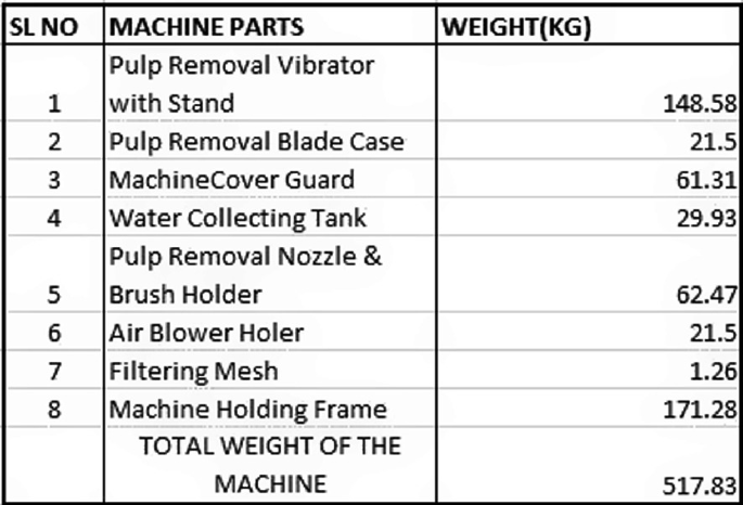
Approximate weight of component parts of pulp removal machine I
Therefore, raw material cost of the pulp removal machine I = Cost per kilogram × Total weight = 140 × 517.83 = 72,496.2 rupees
-
2.
Accessories Cost
Here the cost of other accessories such as nozzle, motor, cutting blade and air blower.
The total accessories cost of automated pulp removal machine I = 19,280 rupees.
-
3.
Total Cost
Total cost = raw material cost + other accessories cost = 72,496.2 + 19,280 = 91,776.2 rupees (excluding labour charges + government tax)

Estimated Cost of Automated Pulp Removal Machine II
-
1.
Raw Material Cost
This includes raw material cost of all parts of the automated pulp removal machine II such as lead screw, machine outer case and frame, bottom cover and water collecting tank.
Proposed raw material weight of the pulp removal machine II = 211.66 kg (see Fig. 20.11). Cost of the aluminium alloy = 140/kg.
Fig. 20.11 
Approximate weight of component parts of pulp removal machine II
Therefore, raw material cost of the pulp removal machine I = Cost per kilogram × Total weight = 140 × 211.66 = 29,632.4 rupees.
-
2.
Accessories Cost
Here the cost of other accessories includes nozzle and motors. The total accessories cost of automated pulp removal machine II = 8480 rupees.
-
3.
Total Cost
Total cost = raw material cost + other accessories cost = 29,632.4 + 8480 = 38,112.4 rupees (excluding labour charges + government tax).

Space Consumed by Automated Pulp Removal Machines
Space utilization is a strategically important space management measure. For the efficient operation of each production process, individual machines and equipment must be used in the maximal possible measure.
Space Consumed by Automated Pulp Removal Machine I
-
Length of the machine = 7256 mm = 7.256 m
-
Width of the machine = 1246 mm = 1.245 m Height of the machine = 1560 mm = 1.560 m
-
Therefore, total floor space consumed = length of machine × with of machine = 7.256 × 1.245 = 9.0337 m2
-
Total volume space consumed = Total floor space × height of the machine = 9.0337 × 1.560 = 14.092 m2.
Space Consumed by Automated Pulp Removal Machine II
This machine is a vertical type machine, which consumes vertical space more compare with horizontal.
The following calculation shows the space utilized by the machine. Length of the machine = 1139 mm.
Width of the machine = 1139 mm, Height of the machine = 2131mm.
Therefore total floor space consumed = length of machine × width of machine = 1.139 × 1.139 = 1.2973 m2.
Total volume space consumed = total floor space × height of the machine = 1.2973 × 2.131 = 2.7645 m2.
Energy Consumed by Automated Pulp Removal Machines
Energy efficiency has become key driver of sustainable development of a firm. Higher energy consumed equipment bring down the profit margin of the organization. Therefore, energy efficient machines play great role with profit of firm. Here we are calculating the energy consumed by the machines. For this, we consider a duration period of one hour. Following shows the energy consumption rate of individual machines.
Energy Consumed by Automated Pulp Removal Machine I
The following are the motor usage and its energy consumption for duration of an hour.
-
(1)
The power consumed by the motor (used in conveyor system) = 1.49 KW
-
(2)
The power consumed by the motor (used in pulp removal vibrator) = 1.49 KW
-
(3)
The power consumed by the motor (used in high pressure nozzle) = 0.372 KW
-
(4)
The power consumed by the motor (used in brushing an cleaning system) = 0.746 KW.
Therefore, the total power consumed by the automated pulp removal machine I for 1 h = total of power consumed by individual motor = 4.096 KW.
Energy Consumed by Automated Pulp Removal Machine II
The following are the motor usage and its energy consumption for duration of an hour.
-
(1)
The power consumed by the motor (used in lead screw mechanism) = 1.49 KW
-
(2)
The power consumed by the motor (used in high pressure nozzle) = 0.372 KW. Therefore, the total power consumed by the automated pulp removal machine.
II for 1 h = total of power consumed by individual motor = 1.862 KW.
Conclusions
The studies show that industrial and environmental issues caused by manual filtration plate cleaning process could be resolved by using the automated pulp cleaning machine. Both the pulp removal machine that is designed could solve the issues caused by manual cleaning. On further study of each individual machine, it shows that the pulp removal machine II has got more advantage than the pulp removal machine I.
In account of cost incurred, energy consumed, space utilized the pulp removal machine II stood at higher end than pulp removal machine I. On the other hand, when coming to the setting time, the pulp removal machine I seems to have upper hand than pulp removal machine II, it is because the pulp removal machine I works with a conveyor system. Although the time taken for the cleaning is almost same, but looking towards future aspect, pulp removal machine I has more advantage than machine II. It is because machine I has higher throughput with less setting time and also its can easily bridge with pre- and post-filtration.
References
Choi YS, Hong SR, Lee YM, Song KW, Park MH, Nam YS (1999) Study on gelatin-containing artificial skin: I. Preparation and characteristics of novel gelatin-alginate sponge. Biomaterials 20:409–417
Abdalbasit Adam Mariod HFA (2014) Review: gelatin, source, extraction and industrial applications 2(2):135–147
Rohit Singh S (2017) Design, development and evaluation of neem Depulper, vol 48(4)
Bajpai P (2018) Biermann’s Handbook of Pulp and Paper Pulp Cleaning, Screening, and Fractionation, 3rd edn, Elsevier India
Jagtap AA, Vaidya S, Samrutwar AR, Kamadi RG, Bhende NV (2015) Design of material handling equipment: belt conveyor system for crushed biomass wood using V merge conveying system 7(7). ISSN: 2278-7798
Fleiter T, Fehrenbach D, Worrell E, Eichhammer W (2012) Energy efficiency in the German pulp and paper industry—a model-based assessment of saving potentials. Energy 40:84–99
Patel J, Rana M (2017) A review work the on lead screw 5(6):302–304. ID: IJSRDV5I60202
Huang XX, Newnes LB, Parry GC (2011) The adaption of product cost estimation techniques to estimate the cost of service, pp 417–431. https://doi.org/10.1080/0951192X.2011.596281
Prasad DS, Shoba C, Ramanaiah N (2014) Investigations on mechanical properties of aluminum hybrid composites 3(1):79–85
Author information
Authors and Affiliations
Corresponding author
Editor information
Editors and Affiliations
Rights and permissions
Copyright information
© 2021 The Author(s), under exclusive license to Springer Nature Singapore Pte Ltd.
About this paper

Cite this paper
Hans Wilson, C., George, B.K. (2021). Designing and Analyzing the Different Parameters of Pulp Removal Machine. In: Kumar, S., Rajurkar, K.P. (eds) Advances in Manufacturing Systems. Lecture Notes in Mechanical Engineering. Springer, Singapore. https://doi.org/10.1007/978-981-33-4466-2_20
Download citation
DOI: https://doi.org/10.1007/978-981-33-4466-2_20
Published:
Publisher Name: Springer, Singapore
Print ISBN: 978-981-33-4465-5
Online ISBN: 978-981-33-4466-2
eBook Packages: EngineeringEngineering (R0)