
Abstract
This paper describes the SPV-based charging system which is capable of acting as a source of power for the infrastructure where it is installed by extracting the power from the electric vehicle batteries under emergency conditions, i.e., when the grid is absent. The simulation is done using a single-phase system on Matlab. The system comprises two sources, namely, the solar and grid, respectively, and the batteries of EV act as a source under emergency conditions.
Access provided by Autonomous University of Puebla. Download conference paper PDF
Keywords
1 Introduction
With the rapid increase in technologies and popularity of EV, a need develops for the improved charging infrastructure for their successful propulsion [1].
The charging could basically be powered by electricity generated from either conventional or non-conventional source of energy. But to make the concept of EVs completely environment-friendly a charging station powered by a renewable source of energy is considered to be the best [2].
Out of many types of renewable sources present on earth like tidal, geothermal, solar, wind energy, etc., the use of solar PV array for the EV charging station is preferred the most due to its easy availability, ease of installation, and less maintenance due to the absence of moving parts [3, 4].
The solar-powered charging system with power backup provides various advantages to the infrastructure where it is installed as it provides free fuel for the EVs throughout its lifetime, 20–25 years approximately, after a single investment and also eliminates the need of the power backup sources like diesel generator, inverters, etc. as it can supply the load by the EV batteries under emergency conditions [5].
2 System Description
See Fig. 1.

Block diagram of the system
2.1 PV Array
A solar PV array of 1 Soltech 1 STH-215-P is used with 10 series modules and 40 parallel strings. The PV and IV characteristics of the PV array are as follows (Figs. 2).

The PV and IV characteristics of the PV array are as follows

The output waveform of the PV array used in this system
Characteristics of PV array
See Fig. 3.
2.2 Boost Converter
A boost converter is a DC–DC converter that steps up voltage (while stepping down the current) from its input to output. It is a category of SMPS (switch mode power supply) containing at least two semiconductors (a diode and a transistor) and at least one energy storage element, a capacitor, an inductor, or two in combination (Fig. 4).

Basic diagram of a boost converter
2.3 Single-Phase Full Bridge Inverter for R-L Load Inverter
A single-phase square wave type voltage source inverter produces square-shaped output voltage for a single-phase load. Such inverters have very simple control logic and the power switches need to operate at much lower frequencies compared to switches in some other types of inverters (Fig. 5).

Basic diagram of a single-phase inverter
2.4 Single-Phase AC Supply
A supply of peak voltage of 180 V and frequency of 50 Hz is used to supply the load under normal conditions.
2.5 Load
A resistive load of 5000 ohms is taken in this system.
3 Working of the System
The working of this system is explained basically in three modes.
-
MODE-I In this mode, both the grid and the SPV are ON where the grid supplies the load and the SPV charges the batteries of electric vehicles.
-
MODE-II In this mode, the grid is absent and the SPV maintains the supply across the load through a single-phase inverter and also charges the batteries of the EVs.
-
MODE-III In this mode, both the PV and the grid are absent and the batteries of the EVs supply the load and their discharging could be seen (Figs. 6, 7 and 8).
Fig. 6 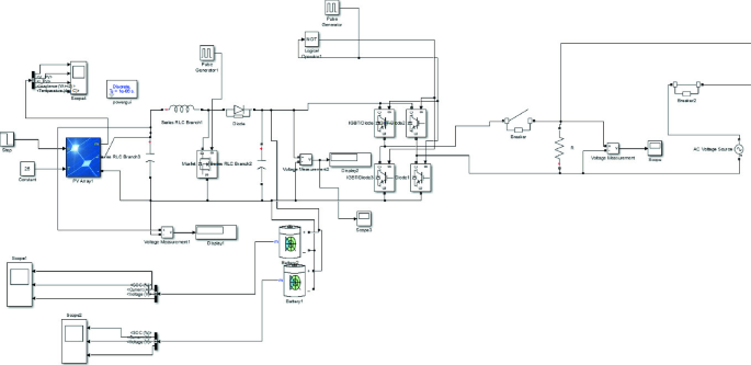
Simulation model of the system in Matlab
Fig. 7 
Output waveforms across the load
Fig.8 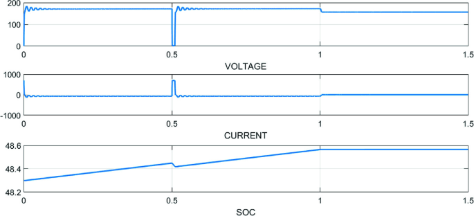
Output waveforms across the battery


4 Simulation Model and Results
In Mode 1, i.e., from a time period of 0–0.5, the output waveforms across the load show sinusoidal waveforms as in this period of time the load is supplied by the grid and the output waveforms across the battery show an increasing value of SOC as it is getting charged by the solar PV array at this time.
In Mode 2, i.e., from time period of 0.5–1, the output waveforms across the load can be seen as a square wave as it is supplied by the solar PV inverter via a single-phase inverter in the absence of grid and the output waveforms across the battery show the increasing SOC as it is getting charged by the solar PV array.
In Mode 3, i.e., from time period of 1–1.5, the output waveforms across the load show the square wave of 144 V approximately which is supplied by the battery via a single-phase inverter due to the absence of both the sources (solar and grid) and discharging of the batteries can be seen in the output waveforms across the battery.
5 Conclusion
The charging station developed in this system proves to be a very economical system as with eliminating the requirements of expensive power backup sources. It also provides free fuel to the EVs throughout its life. The system could be further expanded and could be made more useful by applying some control techniques.
References
Suman N, Yadav DK, Jangid T (2018) Modeling and analysis of photovoltaic system with improved inverter technique. In: 2018 9th international conference on computing, communication and networking technologies (ICCCNT). https://doi.org/10.1109/icccnt.2018.8494168
Koduri N, Kumar S, Uday kumar RY (2014) On-board vehicle-to-Grid (V2G) integrator for power transaction in the smart grid environment. In: 2014 IEEE international conference on computational intelligence and computing research. https://doi.org/10.1109/iccic.2014.7238404
Chen J, Zhang Y, Su W (2015) An anonymous authentication scheme for plug-in electric vehicles joining to charging/discharging station in vehicle-to-Grid (V2G) networks. China Commun 12(3):9–19. https://doi.org/10.1109/cc.2015.7084359
Yang P, PengT, Wang H, Han H, Yang J, Wang H (2017) A single-phase current-source bidirectional converter for V2G application. In: 2017 IEEE 3rd international future energy electronics conference and ECCE Asia (IFEEC 2017 - ECCE Asia). https://doi.org/10.1109/ifeec.2017.7992125
Li Y, Yu G, Liu J, Deng F (2017) Design of V2G auxiliary service system based on 5G technology. In: 2017 IEEE conference on energy internet and energy system integration (EI2). https://doi.org/10.1109/ei2.2017.8245513
Han H, Lv Z, Huang D, Li Q (2017) Research on charge and discharge power tracking control for V2G system. In: 2017 IEEE 2nd information technology, networking, electronic and automation control conference (ITNEC). https://doi.org/10.1109/itnec.2017.8284928
Author information
Authors and Affiliations
Corresponding author
Editor information
Editors and Affiliations
Rights and permissions
Copyright information
© 2021 Springer Nature Singapore Pte Ltd.
About this paper

Cite this paper
Gupta, U., Yadav, D.K., Panchauli, D. (2021). Solar PV-Based Electric Vehicle Charging System with Power Backup. In: Shorif Uddin, M., Sharma, A., Agarwal, K.L., Saraswat, M. (eds) Intelligent Energy Management Technologies. Algorithms for Intelligent Systems. Springer, Singapore. https://doi.org/10.1007/978-981-15-8820-4_1
Download citation
DOI: https://doi.org/10.1007/978-981-15-8820-4_1
Published:
Publisher Name: Springer, Singapore
Print ISBN: 978-981-15-8819-8
Online ISBN: 978-981-15-8820-4
eBook Packages: EngineeringEngineering (R0)