
Abstract
A robust and geometric invariant digital image watermarking scheme based on robust feature detector and local Zernike transform is proposed in this paper. The robust feature extraction method is proposed based on the Scale Invariant Feature Transform (SIFT) algorithm, to extract circular regions/patches for watermarking use. Then a local Zernike moments-based watermarking scheme is raised, where the watermarked regions/patches can be obtained directly by inverse Zernike Transform. Each extracted circular patch is decomposed into a collection of binary patches and Zernike transform is applied to the appointed binary patches. Magnitudes of the local Zernike moments are calculated and modified to embed the watermarks. Experimental results show that the proposed watermarking scheme is very robust against geometric distortion such as rotation, scaling, cropping, and affine transformation; and common signal processing such as JPEG compression, median filtering, and low-pass Gaussian filtering.
1 Introduction
Digital multimedia assets, such as images, music, and videos are allowed to be accessed in digital forms via computer network. As a consequence, the digital watermarking has emerged as a potentially effective tool for multimedia copyright protection and authentication. A desired watermarking scheme must be robust against a variety of possible attacks, which can be classified into common signal processing and geometric distortions; of which, geometric distortion is more difficult to tackle since it brings synchronization errors. Representative geometric distortions include rotation, scaling, cropping, and affine transformations. Quite a number of geometric invariant algorithms have been proposed in the past years [37]. The existing watermarking schemes robust against geometric distortions can be divided into three categories: to embed the watermark in the geometric invariant domain [17, 21, 39]; to embed a template along with the watermark [2, 9]; and to embed the watermark based on feature extraction approaches which recently have been shown to have better performance in terms of robustness [3, 7, 8, 14, 16, 27, 28, 30, 31, 33, 38].
The category of feature based digital image watermarking schemes is to use the salient features in the image as reference points for both embedding and extracting a watermark. Tang and Hang [28] developed a method of combining feature extraction and image normalization to resist geometric distortions. The feature extraction method called Mexican Hat Wavelet scale interaction was used. It was stated that the extracted feature points can survive varieties of attacks and can be used as reference points for both watermark embedding and extraction. Seo and Yoo [27] used Harris-Laplace detector to extract feature points and several copies of the watermarks were embedded in the circular disk centered at the feature points. Zheng et al. [38] proposed a watermarking scheme based on rotation invariant feature and image normalization. The Bayesian image segmentation was used to segment the cover image into several homogeneous regions. The rotation invariant features were extracted from the segmented areas and were selected as reference points. Although the scheme was stated to perform well against rotation, scaling, and JPEG compression, the capacity of the watermarking scheme needs to be improved. Tsai et al. [31] proposed a novel image watermarking approach, which adopted invariant feature regions to jointly enhance its robustness and security. The scale-adapted auto-correlation matrix and the Laplacian-of-Gaussian operation were applied to determine the feature regions. The evaluation results based on the Stir-Mark benchmark presented the proposed scheme can tolerate various attacks, including noise-like signal processing and geometric distortions. Tsai et al. [30] proposed a novel feature region selection method for robust digital image watermarking. It first performed a simulated attacking procedure using some predefined attacks to evaluate the robustness of every candidate feature region; then adopted a track-with-pruning procedure to search a minimal primary feature set which can resist the most predefined attacks. The experimental results indicated that the primary feature set can resist all the predefined attacks and its extension can enhance the robustness against undefined attacks.
Moments and invariant functions of moments have been extensively used for invariant feature extraction in a wide range of pattern recognition applications [1, 6, 24, 25, 36]. Of various types of moments, Zernike moments have been shown to be superior to the others in terms of their insensitivity to image noise, information content, and ability to provide faithful image representation [29]; which are employed for watermarking in many literatures for its special invariance properties against distortions. Xin et al. [34] divided the host image into co-centric rings and modulated a watermark signal into the Zernike moments of each ring. However, the reconstruction procedures were computationally expensive and there was severe fidelity loss. Kim and Lee [12] introduced the semi-blind watermarking scheme based on the invariant image feature vector using Zernike moments. However, a lot of side information was required to extract the embedded watermark and computationally expensive.
In order to overcome the major problems of computationally expensive and severe fidelity loss in the existing approaches, the novel geometric invariant digital image watermarking scheme based on feature extraction and local Zernike moments is proposed in this paper. The Scale Invariant Feature Transform (SIFT) can extract feature points robust against various attacks, such as rotation, scaling, JPEG compression, and also transformation; and it has been used for feature points extraction for watermarking use in previous works [15, 16, 32]. Lee et al. [15] proposed a watermarking method that was robust to geometric distortions. In order to resist geometric distortions, they used the translation and scaling invariant SIFT. The watermark was inserted into the circular patches generated by the SIFT. Rotation invariance was achieved using the translation property of the polar-mapped circular patches. Viet et al. [32] developed a robust object-based watermarking algorithm using the SIFT features in conjunction with a new data embedding method based on Discrete Cosine Transform (DCT). The message was embedded in DCT spaces of randomly generated blocks in the selected object region. To recognize the object region after being distorted, its SIFT features were registered in advance. Experimental results demonstrated that the proposed algorithm was very robust to geometrical distortions.
Therefore, this paper proposes a Robust Feature Points Detector (RFPD) based on SIFT, to extract geometric invariant feature points; and then the circular regions centering at the extracted feature points are defined as watermark embedding and extraction regions. Due to the cumulative computational errors of Zernike transform, it is difficult to reconstruct watermarked image/patch without visible quality degradation directly using its inverse transform. Considering this problem, we proposed a bit-plane decomposition based scheme. Each extracted circular patch is decomposed into a collection of binary images. The Zernike transform is applied to the selected binary patches, and the magnitudes of the local Zernike moments are modified to embed the watermarks. The details of the scheme will be addressed in the following sections. Section 2 describes the SIFT algorithm and the proposed RFPD. Section 3 introduces the Zernike moments and its invariance properties. Section 4 illustrates the detail procedure of watermark embedding and section 5 covers the details of watermark extraction procedure. In section 6, many experimental results are presented to demonstrate the robustness performance of our proposed scheme. And finally the conclusions are drawn in section 7.
2 SIFT and proposed robust feature points detector
The SIFT is an algorithm which transforms an image into a large collection of local feature vectors. According to Lowe [20], the feature points extracted by SIFT are invariant to image scaling, rotation and partially invariant to change in illumination and 3D camera viewpoint. Also they are well localized in both the spatial and frequency domains, reducing the probability of disruption by occlusion, clutter, or noise. Consequently, SIFT is one of the best choices for extracting feature points invariant to geometric distortions. Although the SIFT extracted feature points are said to be very invariant to various distortions, especially geometric attacks, they are not suitable for watermarking for two main reasons. The first one is: so many feature points can be extracted with SIFT that it is difficult to select the suitable ones for watermarking use; the second one is: when the images go through distortions and geometric transforms, some of the feature points cannot be located accurately and some additional feature points may be extracted due to different distortions. Therefore, the RFPD was proposed by improving SIFT algorithm to produce more robust feature points for digital image watermarking. Section 2.1 describes the SIFT algorithm and 2.2 illustrate the proposed RFPD.
2.1 Scale Invariant Feature Transform (SIFT) algorithm
The steps of SIFT algorithm are shown in Fig. 1 and the major stages for generating the SIFT feature points are as following:

SIFT feature points’ generation
-
STEP-1
Apply the difference-of-Gaussian (DoG) function to the host image and look for the maxima or minima to identify locations of the feature with potential interest in scale space.
For the DoG in STEP-1, Koenderink [13] and Lindeberg [18] showed that the only possible scale-space kernel is the Gaussian function, under a variety of reasonable assumptions. Lowe [19] proposed the Gaussian scale model which use scale-space extreme in the DoG function convolved with the image, to locate the geometric-transform-invariant feature points.
The scale space of an image is defined as a function, L(x, y, σ), which can be defined by:
$$ L\left( {x,y,\sigma } \right)=G\left( {x,y,\sigma } \right)*f\left( {x,y} \right) $$(1)Where f(x, y) is the input image, * is the convolution operation in x and y, and G(x, y, σ) is the Gaussian filter, which is defined in Eq. (2).
$$ G\left( {x,y,\sigma } \right)=\frac{1}{{2\pi {\sigma^2}}}{e^{{{{{-\left( {{x^2}+{y^2}} \right)}} \left/ {{2{\sigma^2}}} \right.}}}} $$(2)Thus the DoG filtered image can be computed with Eq. (5), from the difference of two nearby scales separated by a constant multiplicative factor k:
$$ \mathrm{DoG}=\left( {G\left( {x,y,k\sigma } \right)-G\left( {x,y,\sigma } \right)} \right)*f\left( {x,y} \right) $$(3)$$ \mathrm{DoG}=G\left( {x,y,k\sigma } \right)*f\left( {x,y} \right)-G\left( {x,y,\sigma } \right)*f\left( {x,y} \right) $$(4)$$ \mathrm{DoG}=L\left( {x,y,k\sigma } \right)-L\left( {x,y,\sigma } \right) $$(5)To detect the local maxima and minima of DoG in Eq. (5), each sample point is compared to its eight neighbors in the current image and the nine neighbors in the scale above and below. The feature points are selected when they are larger than all of their neighbors or smaller than all of them.
-
STEP-2
Select the feature points from the candidates based on measures of their stability and assign each feature point location with one or more orientations, based on the local image gradient directions.
In STEP-2, the orientation assignment in [20] is used to make the feature points rotation invariant. A consistent orientation is assigned to each feature point based on the local image properties. The gradient magnitude,m(x, y), and orientation, θ(x, y), is computed using Eqs. (6) and (7), respectively.
$$ m\left( {x,y} \right)=\sqrt{{{{{\left( {L\left( {x+1,y} \right)-L\left( {x-1,y} \right)} \right)}}^2}+{{{\left( {L\left( {x,y+1} \right)-L\left( {x,y-1} \right)} \right)}}^2}}} $$(6)$$ \theta \left( {x,y} \right)={\tan^{-1 }}\left. {{{{\left( {L\left( {x,y+1} \right)-L\left( {x,y-1} \right)} \right)}} \left/ {{\left( {L\left( {x+1,y} \right)-L\left( {x-1,y} \right)} \right)}} \right.}} \right) $$(7) -
STEP-3
Create the feature point descriptor by measuring the gradient magnitude and orientation at each image sample point in a region around the feature point location.
After assigning the location, scale, and orientation to the feature points, the descriptor for the local image region is computed in STEP-3. Figure 2 illustrates the computation of the feature point descriptor. Firstly, the image gradient magnitudes and orientations are sampled around the feature points’ location, as Fig. 2a shows. The descriptor is formed from a vector containing the values of all the orientation histogram entries, corresponding to the lengths of the arrows in Fig. 2b. Lowe [20] did many experiments to show that the best results were achieved with a 4 × 4 array of histograms with eight orientation bins in each. Therefore, the following experiments use a 4 × 4 × 8 = 128 element feature vector for each feature points.
Fig. 2 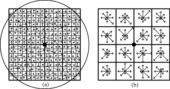
Feature points descriptor (a) computation of the gradient magnitude and orientation at each image sample point in a region around the feature point location (b) the 4 × 4 descriptors computed from a 16 × 16 sample array

2.2 Proposed Robust Feature Points Detector (RFPD) algorithm
In the proposed RFPD, the host images are trained with some common signal processing and geometric attacks, such as rotation, scaling and JPEG compression; the SIFT algorithm is applied into the host images and the trained images, respectively, to extract the original feature points dataset and the trained feature points dataset. The feature points matching algorithm is then applied to these two datasets to extract the matched points as the feature points, according to their robustness. The robustness is the distance ratio of the nearest neighbor to the second-nearest neighbor in the SIFT algorithm. Hence, the parameter distance ratio (distRatio) can be adjusted to generate different number of required feature points for image watermarking. The final value of the distRatio is obtained through experiments. The detailed algorithm of RFPD is explained in following and the flow chart is shown in Fig. 3. In our experiments, the host images are trained in STEP-1 with image rotation with rotation angle as 45°, image scaling with the scaling factor as 0.5, JPEG compression with the quality factor as 50, and median filtering with the neighborhood as 4 × 4. With the RFPD, given number of feature points can be extracted, in our experiments, N is set to be 8 and the initial distRatio value is set to be 0.15.

Flow chart of RFPD
2.3 Robust Feature Point Detector (RFPD) algorithm
-
Input: Host Image; Minimum Number of Feature Points – N.
-
Output: N Feature Points with Descriptor Given.
-
STEP-1
Load the host image and apply some common signal processing and geometric attacks into the host image to generate the trained image.
-
STEP-2
Apply the SIFT algorithm to the host image and the trained image, to generate the original feature points dataset (OFPD) and the trained feature points dataset (TFPD), respectively.
-
STEP-3
Find the matching between the OFPD and TFPD, with the distRatio value, which is obtained through the experimental results, using the feature point matching.
-
STEP-4
Count the number of extracted feature points as C, and compare it with the given N. If C < N, recursively increase distRatio; if C > 1.5N, recursively decrease distRatio, then repeat STEP-3 with the updated distRatio value; until C meets the requirements.
-
STEP-5
Finally, the robust feature points, with the number meet the requirements, are extracted with their location and descriptor given.
3 Zernike moments and invariance properties
Zernike moments have been widely used in pattern recognition and image processing, and they are also powerful feature descriptors that they can be adopted for robust watermarking [10, 12, 34]. This section describes the Zernike moments and explains why we choose them as the watermark carrier and how to achieve the RST invariance using them [10–12, 22]. Zernike moments are orthogonal moments and they consist of a set of complex polynomials that form a complete orthogonal set over the interior of a unit disk. The Zernike moment of order n with repetition m for a continuous image function f(x, y) that vanishes outside a unit disk is defined as:
Where n is a nonnegative integer; m is an integer such that n - |m| is nonnegative and even. The complex-valued function V nm (x, y) is the polynomial, which forms a complete orthogonal set over the interior of the unit circle, and it is defined as:
Where ρ andθ represent polar coordinates over the unit disk. ρ is the length of vector from origin to (x, y) pixel, \( \rho =\sqrt{{{x^2}+{y^2}}} \); and is the angle between vector ρ and x axis in counterclockwise direction, \( \theta ={\tan^{-1 }}\left( {\frac{y}{x}} \right) \). R nm is the Radial polynomials given by Eq. (10):
Note that \( {R_{nm }}\left( \rho \right)={R_{{n\prime -m}}}\left( \rho \right) \).
For a digital image, the integrals in Eq. (8) are replaced by summations and the Zernike moments are calculated as Eq. (11). To compute the Zernike moments of a given image, the center of the image is taken as the origin and pixel coordinates are mapped to the range of unit circle.
Zernike moments are such powerful feature descriptors that they can be adopted for robust watermarking. The defined features on the Zernike moments are only rotational invariance which can be easily constructed in [10]. In order to obtain the scale and translation invariance, the input image for digital watermarking needs to be translated to its centroid and scaled to a standard size. Since the Zernike moments’ magnitudes are only invariant to rotation; to achieve scaling and translation invariance, the appointed patch needs to be normalized using regular moments [10], which means the center of the corresponding patch is taken as the origin and pixel coordinates are mapped to the range of the unit circle. Then the magnitudes of the Zernike moments extracted from the scale and translation normalized image are total geometric invariant for watermark embedding scheme. An image function f(x, y) can be normalized with respect to scale and translation by transforming it into g(x, y) [5].
Where \( \left( {\overline{x},\overline{y}} \right) \) is the centroid of f(x, y). \( a=\sqrt{{\frac{\beta }{{{m_{00 }}}}}} \), β is a predetermined value and m 00 is its zero-order moment.
The orthogonality property enables that the individual contribution of each order moment can be separated out to the reconstruction process. Simple addition of the individual contributions generates the reconstructed image. Given all the Zernike moments A nm of f(x, y) up to a given order N, we can reconstruct \( \widehat{f}\left( {x,y} \right) \) as Eq. (13):
\( \widehat{f}\left( {x,y} \right) \) is a discrete original image function whose moments exactly match those of f(x, y) up to the given order N. When N approaches infinity, \( \widehat{f}\left( {x,y} \right) \) will approach f(x, y).
4 Watermark embedding using Zernike transform
In the proposed watermark embedding scheme, firstly, the proposed RFPD as described in section 2.2 is applied into the host image to extract the feature points, which can be relocated during watermark extraction procedure, thus the circular patches centering at the extracted feature points can be generated for watermark embedding and extraction. The proposed RFPD is robust against image attacks such as rotation, scaling, affine transformation, cropping, JPEG compression, median filtering and so on.
Each extracted patch is decomposed into m binary circular patches, respectively, with the bit-plane based method that separate the m coefficients of the polynomial into m 1-bit planes, I 0, I 1, I 2,…,I m−1, where the highest order bit plane corresponds to the most significant bit. Some of the binary patches are appointed for watermark data bits embedding.
For each appointed patch, the appointed binary circular patch I app is translated to its centroid, and is scaled to a standard size; afterwards, Zernike transform is applied into the scale and translation normalized binary patch \( I_{app}^{\prime } \) to calculate its Zernike moments m Zer with the given order O. The magnitudes of m Zer are proved to be so robust against RST attacks that they are used as watermark embedder.
The watermark data sequence W of Gaussian distribution can be generated with a predefined seed. This paper uses spread spectrum communication techniques to embed the watermark [4], the watermarking formula is defined in Eq. (14).
Where X denotes the Zernike moments magnitudes calculated from each selected binary patch I app , which is the served binary patch decomposed from each extracted circular patch; α is the predefined parameter to control the watermark embedding strength, and W presents the random watermark sequence of Gaussian distribution and it is the same size as X. Y is the watermarked data. The generated watermark is repeatedly embedded into the Zernike moments’ magnitudes M Zer using watermarking Eq. (14).
After the watermark being embedded, inverse Zernike transform is applied to reconstruct the corresponding binary patch from the watermarked Zernike moments. Then each watermarked patches can be obtained by recomposing process with Eq. (15).
Where I i denotes the corresponding decomposed bit plane patch.
And finally, we can obtain the watermarked image by replacing the original patches with the watermarked patches. The flow chart of watermark embedding procedure is shown in Fig. 4 and the procedure is in following:

Flow chart of watermark embedding procedure
4.1 Watermarking embedding algorithm
-
Input: Host Image; Seed.
-
Output: Watermarked Image, KEY.
-
STEP-1
Load the host image and apply the proposed RFPD into it to extract the circular patches for watermark embedding.
-
STEP-2
Decompose each extracted patch into m binary circular patches with Bit-Plane Decomposition method.
-
STEP-3
Translate each appointed binary circular patch to its centroid, and scale it to a standard size; afterwards, apply Zernike transform into them to calculate their Zernike moments, respectively.
-
STEP-4
Generate the watermark data sequence W of Gaussian distribution with the given seed and embed the watermark into the Zernike moments’ magnitudes. The seed and the descriptor D generated in STEP-1 are encoded as a KEY.
-
STEP-5
Apply inverse Zernike transform to reconstruct the corresponding binary patches; and recompose the watermarked binary patch with all the other binary patches to obtain the corresponding watermarked patch.
-
STEP-6
Replace each circular patch in the host image with the corresponding watermarked patch to obtain the watermarked image.
5 Watermark extraction using Zernike transform
For the proposed watermark extraction procedure as shown in Fig. 5, the SIFT algorithm is applied to the watermarked image to generate a feature points database. The descriptor D and the seed are decoded from the KEY, and the matching for D is found from the generated feature points dataset, using feature points matching algorithm, and the matched features can be extracted for watermark extraction. The descriptor D depends on the host image, different host images correspond to different descriptors. Besides, the seed for generating watermark sequence is necessary for the spread-spectrum watermarking method to judge whether the watermark exists or not. Consequently, although we don’t need the watermarked image for watermark detection; we need the KEY, from which the descriptor D and the seed can be decoded, for re-locating the feature points for watermark extraction. Therefore, our proposed watermarking scheme is semi-blind. With the extracted feature points, the circular patches I extr are extracted for watermark extraction. Then each I extr is decomposed into m binary circular patches, I extr_0, I extr_1, I extr_2,…,I extr_m−1. The same specified binary patches as the ones used as watermark embedder during watermark embedding process are appointed for watermark extraction.

Flow chart of watermark extraction procedure
After that, each appointed binary circular patch is translated to its centroid, and is scaled to a standard size; and Zernike transform is applied into it to calculate its Zernike moments m Zer_extr with the given order O, which is the same value as the one used in watermark embedding procedure. The same watermark data sequence W as the one used for watermark embedding is generated with the given seed. For watermark detection, the linear correlation [38] is used to detect the existence of the watermark in the Zernike moments magnitudes and it is defined in Eq. (16). The watermark is detected when the result is larger than a predefined threshold value. The procedure of watermark extraction is as following.
Where C Linear is the linear correlation, S is size of the Zernike moments magnitudes for watermark detection, y is the watermarked data, and w is the watermark data sequence generated by using the same seed used in watermark embedding process.
5.1 Watermark extraction algorithm
-
Input: Watermarked Image; KEY;
-
Output: Linear Correlation C Linear .
-
STEP-1
Load the watermarked image and apply the SIFT algorithm into it to generate the corresponding feature points database.
-
STEP-2
Decode the KEY to obtain the descriptor D and the seed; use feature points matching algorithm to find the match between D and the feature points dataset generated in STEP-1. The patches centering at the matched feature points are consequently extracted.
-
STEP-3
Decompose each extracted patch into series of binary circular patches using the Bit-Plane Decomposition method.
-
STEP-4
Translate and scale each appointed binary circular patch and apply Zernike transform into them to calculate their Zernike moments.
-
STEP-5
Generate the same watermark data sequence as the one used for watermark embedding with the seed decoded in STEP-2; and calculate the linear correlation between the watermark and the calculated Zernike moments magnitudes. The watermark is detected when the result is larger than a predefined threshold value.
6 Experimental results
Many experiments are implemented to evaluate the proposed watermarking scheme on the popular test images, which are standard gray images of size 512 × 512 selected from the USC-SIPI Image Database. In the following experiments, six representative images: ‘Baboon’, ‘Bridge’, ‘Lena’, ‘Pepper’, ‘Blurry Scene’, and ‘Blurry Jet’ are selected to test the proposed watermarking scheme; where the ‘Blurry Scene’ and ‘Blurry Jet’ are generated by filtering the original ‘Scene’ and ‘Jet’ using Gaussian low-pass filterer of size of 3 × 3, with the standard deviation as 2. The minimum number of feature points N is set to be eight, which means, at least eight feature points can be extracted by the proposed RFPD for each test image. The radius r of the circular patches depend on the size of the test images; by experimental results, in the following experiments, with the size of the test images as 512 × 512, the radius r is set to be 40. Zernike transform with its order O defined as 40 is applied to the appointed scale and translation normalized binary patches to calculate their Zernike moments, respectively. The watermark data sequence is generated randomly under Gaussian distribution and the watermark embedding strength α is set to be 100. Peal Signal-to-Noise Ratio (PSNR) is used to evaluate the distortion of the watermarked image; the larger PSNR value means less distortion. Our proposed scheme has been implemented using Matlab, which takes around 203.98 s in average to embed and then extract a watermark using a Windows 7 PC with CPU 2.67 GHz.
In order to select the most appropriate patch for watermarking among the series of bit planes decomposed from each extracted circular patch, the same watermark data sequence is embedded into each binary patch respectively, the extraction is tested and the PSNR is calculated. The experiment results indicate that the first three least significant bit planes are inadaptable for watermarking for the extraction failed for some test images. Furthermore, the PSNR becomes lower as the order of the bit plane becomes higher. Consequently, in this scheme, the fifth bit plane of each extracted circular patch is selected for watermarking, to ensure both the success of watermark extraction and the imperceptibility of the watermark.
In the proposed scheme, only the extracted regions are modified to embed the watermark. This can significantly decrease the distortion and have better visibility for the watermarked image, compared with many other approaches, which usually need to modify the whole image. Besides, in order to demonstrate our proposed watermarking embedding algorithm has only little distortion to the image, we also measure the PSNR not only over the entire image, but also over each watermarked patch. Figure 6 shows the circular patches extracted from the test images and the corresponding watermarked images; also the PSNRs between the original images/patches and their watermarked images/patches are given. In Fig. 6, ‘PSNR’ means the PSNR value of the whole corresponding watermarked image; while ‘AVG_PSNR’ means the average PSNR value of the corresponding watermarked patches. The PSNRs over the entire images are: 39.10, 39.55, 39.96, 38.93, 39.89, and 38.85 dB for ‘Baboon’, ‘Bridge’, ‘Lena’, ‘Pepper’, ‘Blurry Scene’ and ‘Blurry Jet’, respectively. The AVG_PSNRs over the watermarked patches are: 32.43, 32.78, 32.61, 32.24, 32.45, and 32.55 dB for the six test images, respectively.

RFPD extracted features and watermarked images (a1) ‘Baboon’ (a2) watermarked ‘Baboon’, PSNR = 39.10 dB, AVG_PSNR = 32.43 dB; (b1) ‘Bridge’ (b2) watermarked ‘Bridge’, PSNR = 39.55Db, AVG_PSNR = 32.78 dB; (c1) ‘Lena’ (c2) watermarked ‘Lena’, PSNR = 39.96 dB, AVG_PSNR = 32.61 dB; (d1) ‘Pepper’ (d2) watermarked ‘Pepper’, PSNR = 38.93 dB, AVG_PSNR = 32.24 dB; (e1) ‘Blurry Scene’ (e2) watermarked ‘Blurry Scene’, PSNR = 39.89 dB, AVG_PSNR = 32.45 dB; (f1) ‘Blurry Jet’ (f2) watermarked ‘Blurry Jet’, PSNR = 38.85 dB, AVG_PSNR = 32.55 dB
Figure 7 shows the extracted patches from the watermarked images under various attacks. (a1)–(d1) show the original images; Others show the watermarked image attacked by: (a2)–(d2) Rotation and cropping, the rotation angle is 45o, where A/B = 7/10, 9/11, 8/9, 7/10 for ‘Baboon’, ‘Bridge’, ‘Lena’, and ‘Pepper’; (a3)–(d3) Affine transformation of vertical shearing, with the shearing percentage of 20 %, where A/B = 7/10, 10/11, 8/9, 10/10 for ‘Baboon’, ‘Bridge’, ‘Lena’, and ‘Pepper’; (a4)–(d4) Affine transformation of horizontal shearing, with the shearing percentage of 20 %, where A/B = 7/10, 9/11, 8/9, 10/10 for ‘Baboon’, ‘Bridge’, ‘Lena’, and ‘Pepper’; (a5)–(d5) Affine transformation, with the shearing percentage of 10 %, where A/B = 7/10, 9/11, 8/9, 10/10 for ‘Baboon’, ‘Bridge’, ‘Lena’, and ‘Pepper’; (a6)–(d6) Scaling, with the scale factor of 0.5, where A/B = 8/10, 11/11, 8/9, 10/10 for ‘Baboon’, ‘Bridge’, ‘Lena’, and ‘Pepper’; (a7)–(d7) Median filtering, its neighborhood is 4 × 4, where A/B = 7/10, 11/11, 7/9, 9/10 for ‘Baboon’, ‘Bridge’, ‘Lena’, and ‘Pepper’; (a8)–(d8) JPEG compression, with the quality factor of 50, where A/B = 7/10, 11/11, 7/9, 10/10 for ‘Baboon’, ‘Bridge’, ‘Lena’, and ‘Pepper’. For the A/B, A means the number of patches successfully detected from attacked watermarked images, and B means the number of original watermarked patches. In our scheme, as long as one patch correctly extracted, the watermark extraction will be successful. In Fig. 7, the circular patches highlighted in red are the ones correctly extracted; from which, it can be easily seen that most of the patches can be successfully extracted when the watermarked image is distorted by various attacks.

Feature extraction by RFPD when under various attacks (a1)–(d1) original ‘Baboon’, ‘Bridge’, ‘Lena’, ‘Pepper’ (a2)–(d2) 45o rotation with cropping (a3)–(d3) 20 % vertical shearing (a4)–(d4) 20 % horizontal shearing (a5)–(d5) 10 % affine transformation (a6)–(d6) scaling with the scale factor as 0.5 (a7)–(d7) 4 × 4 median filtering (a8) JPEG compression with the quality factor as 50
6.1 Watermarking performance under different distortions
The digital image attacks can roughly be classified into two categories: geometric distortions, such as rotation, scaling, cropping, and affine transformation; and common signal processing, such as JPEG compression, Median filtering, and Gaussian low-pass filtering. The following experiment results demonstrate these two types of attacks on the test images ‘Pepper’ and ‘Lena’. As well, the mixed attacks are tested.
-
(1)
Geometric Distortions: The proposed scheme is tested under various geometric distortions: image rotation and cropping, with the rotation angle varying from 0o to 360o with a step of 10o; image scaling with scale factor varying from 0.3 to 3, with a step of 0.1; and affine transformation of vertical and horizontal shearing with the shearing parameter varying from 2 % to 30 %, with a step of 2 %. The experimental results are shown in Fig. 8. The vertical axis of each sub-figure displays the relative values of linear correlations; and the horizontal axis indicates the rotation angles, scaling factor, and shearing percentage, respectively. Figure 8a demonstrates that the proposed scheme is very rotation invariant that the watermarked images can be distinguished from the un-watermarked ones under any rotation angle. Figure 8b, c, and d demonstrate that the watermarked images can be distinguished from the un-watermarked ones when the scaling factor exceeds 0.3, or when the shearing percentage is less than 30 %, respectively; which means that the proposed scheme is robust against image scaling with the scaling factor bigger than or equal to 0.3; against affine transformation of vertical and horizontal shearing with the shearing percentage up to 30 %.
Fig. 8 
Experimental results against geometric attacks (a) rotation with cropping (b) scaling (c) affine transformation of vertical shearing (d) affine transformation of horizontal shearing
-
(2)
Common Signal Processing: The proposed scheme is also tested under common signal processing of JPEG compression, median filtering, and Gaussian low-pass filtering. The experimental results are shown in Fig. 9. In Fig. 9a, horizontal axis indicates the quality factor, which indicates the effect of JPEG compression. With the quality factor varied from 100 to 10 with a step of −10, the results demonstrate that the watermarked images can be distinguished from the un-watermarked ones; which mean the proposed scheme is robust against JPEG compression with a low quality factor of 10. In Fig. 9b, the watermarked images are filtered in different median filters. The horizontal axis indicates the neighborhood of the median filter. Experimental results show that the proposed scheme is robust against median filtering with its neighborhood up to 10 × 10. In Fig. 9c, a 3 × 3, 6 × 6, and 9 × 9 Gaussian low-pass filter is applied to the watermarked images, respectively. The standard deviation of the Gaussian low-pass filter varies from 0.1 to 2, with a step of 0.1; the horizontal axis indicates the standard deviation of the filter. The results demonstrate that the proposed scheme works well against Gaussian low-pass filtering with the standard deviation of the filter up to 2.
Fig. 9 
Experimental results against common signal processing (a) JPEG compression (b) median filtering; (c) Gaussian low-pass filtering
-
(3)
Mixed Attacks: The proposed scheme is also tested when several watermarked images are mixed together and then geometrically transformed. In Fig. 10, the proposed watermark embedding scheme is applied to the test images ‘Lena’ and ‘Pepper’, thus the watermarked ‘Lena’ and ‘Pepper’ and their corresponding KEY are generated. Then the watermarked ‘Lena’ is scaled and mixed with the watermarked ‘Pepper’; after that, the mixed ‘Le-pper’ is distorted by the representative geometrical attacks such as rotation with cropping and affine transformation. The proposed watermark extraction scheme is applied to the attacked mixed ‘Le-pper’; the patches can be extracted for watermarks extraction, for the two mixed images respectively, with the corresponding KEY. In Fig. 10a, the mixed image is distorted by 30° rotation with cropping, the detection ratio, which means the successfully detected patches to the total watermarked patches, is 7/10 for background image ‘Pepper’, and 7/9 for foreground image ‘Lena’. In Fig. 10b, the mixed image is distorted by affine transformation of 15 %, the detection ratio is 9/10 for background image ‘Pepper’, and 7/9 for foreground image ‘Lena’. Therefore, the proposed scheme is very robust against mixed attacks; on the other hand, this characteristic is beneficial for enlarge the watermarking capacity.
Fig. 10 
Mixed Attacks Demonstration (a) 30° rotation with cropping, detection ratio = 7/10, 7/9 for ‘Pepper’ and ‘Lena’, respectively; (b) 15 % affine transformation, detection ratio = 9/10, 7/9 for ‘Pepper’ and ‘Lena’, respectively
-
(4)
Bit-Error Rates against Strength of Attacks: Besides the correlation plots, the bit-error rate plots are also displayed to determine the performance of the system. Figure 11 shows the bit-error rate against strength of various attacks. The same test images: ‘Pepper’ and ‘Lena’, and the four representative attacks: JPEG Compression, rotation, scaling, and affine transformation, are chosen to display the experimental results; the blue dash-line indicates bit-error rate of ‘Pepper’ and the red dash-line indicates ‘Lena’. In Fig. 11, vertical axis indicates the bit-error rate, and horizontal axis indicates the quality factor, the rotated angles, the scaling factor, and the shearing percentage, respectively, for the four sub-figures; from which, we can easily see the bit-error rate’s transition against the strength of attacks. For example, in Fig. 11a, the bit-error rate decreased when the quality factor varied from 10 to 100, which means the bigger qualify factor, the less effect caused by JPEG compression, the smaller bit-error rate. In Fig. 11d, the bit-error rate increased when the shearing percentage varying from 2 % to 30 %, which means the larger shearing percentage, the bigger bit-error rate.
Fig. 11 
Bit-error rate against strength of various attacks (a) JPEG Compression (b) rotation (c) scaling (d) affine transformation of shearing


6.2 Performance comparison
Stirmark 4.0 [23] is used to evaluate the robustness of the proposed scheme. Tables 1 and 2 present the watermark detection results of the proposed watermarking scheme in comparison with three representative feature-based schemes proposed by Tang and Hang [28], Seo and Yoo [26, 27], and Gao et al. [8], under common signal processing operations and geometric distortions, respectively; using the similar experimental settings mentioned in [8]. The experimental results of the three existing methods used for comparison with the proposed scheme in Tables 1 and 2 were obtained from [8] as well. For values in main table unites, the numerator means the number of patches where watermarks are successfully detected from attacked images, and the denominator means the number of original watermarked patches.
With the simulation results, the proposed RFPD and Zernike based scheme is compared with the existing representative feature-based schemes proposed by Tang and Hang [28] in 2003, and Zheng et al. [38] in 2009, under amounts of attacks, including rotation, scaling, cropping, affine transformation, JPEG Compression, median filtering, and so on. Besides, the proposed scheme is compared with a geometrically invariant watermarking scheme which we proposed before [35]; comparing with which, in this paper we propose a totally new and different feature point detection method called RFPD, which improves the robustness of the extracted feature points over the previous one. Table 3 presents the comparison of the proposed scheme with the other schemes, revealing it performs well compared with the existing methods. According to Table 3, it can be easily seen that the proposed RFPD based scheme improves over the existing schemes; for example, the proposed scheme is robust against scaling with the scale factor up to 0.3 while the others were mostly up to 0.7; the proposed scheme is robust against Median filtering with the filter neighbor up to 10 × 10 while the others were mostly up to 8 × 8. Also the proposed scheme is robust against mixed attacks while the others can’t.
7 Conclusion
In this paper, the digital image watermarking scheme based on feature extraction and local Zernike transform is proposed. The RFPD is proposed for local region extraction, with which, the distinct circular patches of given size can be extracted for watermark embedding and extraction. Bit-plane decomposition method is used to decompose each extracted circular patch into a collection of binary patches. Zernike transform is applied to each appointed binary patches to calculate their Zernike moments for watermarking use.
The proposed scheme can survive both geometric distortions and common signal processing. In the respect of geometric distortion, the scheme is very robust against image rotation with the rotation angle from 0o to 360o; it is robust against image scaling when the scale factor exceeds 0.3; and image cropping with the cropping percentage up to 40 %; also it is robust against affine transformation of shearing with the shearing percentage both up to 30 %, for vertical and horizontal shearing, respectively. For common signal processing, the scheme is robust against JPEG compression with a low quality factor of up to 10, against median filtering with its neighborhood up to 10 × 10 and against Gaussian low-pass filtering of size of 3 × 3, 6 × 6, and 9 × 9, with the standard deviation of the filter up to 2. Besides, the scheme is robust against some combined attacks. The comparison results show the proposed scheme outperforms the several representative feature extraction based schemes in terms of robustness to various attacks.
References
Abu-Mostafa YS, Psaltis D (1985) Image normalization by complex moments. IEEE Trans Pattern Anal Mach Intell 7(1):46–55
Bas P, Chassery JM, Macq B (2000) Robust watermarking based on the warping of pre-defined triangular patterns. Proc SPIE Secur Watermark Multimed Contents 3971:99–109
Bas P, Chassery JM, Macq B (2002) Geometrically invariant watermarking using feature points. IEEE Trans Image Process 11(9):1014–1028
Cox I, Miller M, Bloom J (2002) Digital watermarking. Morgan-Kaufmann, San Francisco
Dong P, Galatsanos NP (2002) Affine transformation resistant watermarking based on image normalization. In: Image processing. Proceedings. 2002 International Conference on, 24–28 June 2002. pp 489–492
Dudani SA, Breeding KJ, McGhee RB (1977) Aircraft identification by moment invariants. IEEE Trans Comput 26(1):39–46
Filipe J, Obaidat MS, Scagliola M, Guccione P (2009) Geometric distortion resilient watermarking based on a single robust feature for still images. In: e-business and telecommunications, vol 48. Communications in computer and information science. Springer, Berlin, pp 345–357
Gao XB, Deng C, Li XL, Tao DC (2010) Geometric distortion insensitive image watermarking in affine covariant regions. IEEE Trans Syst Man Cybern Part C Appl Rev 40(3):278–286
Kang XG, Huang JW, Yun QS, Yan L (2003) A DWT-DFT composite watermarking scheme robust to both affine transform and JPEG compression. IEEE Trans Circ Syst Video Technol 13(8):776–786
Khotanzad A, Hong YH (1990) Invariant image recognition by Zernike moments. IEEE Trans Pattern Anal Mach Intell 12(5):489–497
Khotanzad A, Lu JH (1990) Classification of invariant image representations using a neural network. IEEE Trans Acoust Speech Signal Proc 38(6):1028–1038
Kim HS, Lee H-K (2003) Invariant image watermark using Zernike moments. IEEE Trans Circ Syst Video Technol 13(8):766–775
Koenderink JJ (1984) The structure of images. Biol Cybern 50:363–370
Lee HY, Kang IK, Lee HK, Suh YH (2005) Evaluation of feature extraction techniques for robust watermarking. In: The 4th International Workshop on Digital Watermarking, Siena, Italy, September 15–17 2005. Lecture Notes in Computer Science 3710, Springer 2005: 2418–2431
Lee HY, Kim H, Lee HK (2006) Robust image watermarking using local invariant features. Opt Eng 45(3):037002-1-037002-11
Lin YT, Huang CY, Lee GC (2011) Rotation, scaling, and translation resilient watermarking for images. IET Image Process 5(4):328–340
Lin CY, Wu M, Bloom JA, Cox IJ, Miller ML, Lui YM (2001) Rotation, scale, and translation resilient watermarking for images. IEEE Trans Image Process 10(5):767–782
Lindeberg T (1994) Scale-space theory: a basic tool for analysing structures at different scales. J Appl Stat 21(2):224–270
Lowe DG (1999) Object recognition from local scale-invariant features. In International Conference on Computer Vision, Corfu, Greece, 1999. pp 1150–1157
Lowe DG (2004) Distinctive image features from scale-invariant keypoints. Int J Comput Vis 60(2):91–110
O'Ruanaidh J, Pun T (1998) Rotation, scale, and translation invariant digital image watermarking. Signal Process 66(3):303–317
Perantonis SJ, Lisboa PJG (1992) Translation, rotation, and scale invariant pattern recognition by high-order neural networks and moment classifiers. IEEE Trans Neural Netw 3(2):241–251
Petitcolas FAP (2000) Watermarking schemes evaluation. IEEE Signal Process Mag 17(5):58–64
Reddi SS (1981) Radial and angular moment invariants for image identification. IEEE Trans Pattern Anal Mach Intell 3(2):240–242
Reeves AP, Prokop RJ, Andrews SE, Kuhl FP (1988) Three-dimensional shape analysis using moments and Fourier descriptors. IEEE Trans Pattern Anal Mach Intell 10(6):937–943
Seo JS, Yoo CD (2004) Localized image watermarking based on feature points of scale-space representation. Pattern Recogn 37(7):1365–1375
Seo JS, Yoo CD (2006) Image watermarking based on invariant regions of scale-space representation. IEEE Trans Signal Process 54(4):1537–1549
Tang CW, Hang HM (2003) A feature-based robust digital image watermarking scheme. IEEE Trans Signal Process 51(4):950–959
Teh CH, Chin RT (1988) On image analysis by the methods of moments. IEEE Trans Pattern Anal Mach Intell 10(4):496–513
Tsai JS, Huang WB, Kuo YH (2011) On the selection of optimal feature region set for robust digital image watermarking. IEEE Trans Image Process 20(3):735–743
Tsai JS, Huang WB, Kuo YH, Horng MF (2012) Joint robustness and security enhancement for feature-based image watermarking using invariant feature regions. Signal Process 92(6):1431–1445
Viet QP, Miyaki T, Yamasaki T, Aizawa K (2007) Geometrically invariant object-based watermarking using SIFT feature. In Image processing. ICIP 2007. IEEE International Conference on, Sept. 16–Oct. 19 2007, pp 473–476
Wang XY, Meng L, Yang HY (2009) Geometrically invariant color image watermarking scheme using feature points. Sci China Ser F: Inform Sci 52(9):1605–1616
Xin Y, Liao S, Pawlak M (2004) A multibit geometrically robust image watermark based on Zernike moments. In: Pattern recognition. ICPR 2004. Proceedings of the 17th International Conference on, 23–26 Aug. 2004. pp 861–864
Yuan XC, Pun CM (2012) Geometrically invariant image watermarking based on feature extraction and Zernike transform. Int J Secur Appl 6(2):217–222
Zhang H, Shu H, Coatrieux G, Zhu J, Wu QM, Zhang Y, Zhu H, Luo L (2011) Affine Legendre moment invariants for image watermarking robust to geometric distortions. IEEE Trans Image Process 20(8):2189–2199
Zheng D, Liu Y, Zhao J, Saddik AE (2007) A survey of RST invariant image watermarking algorithms. ACM Comput Surv 39(2):5. doi:10.1145/1242471.1242473
Zheng D, Wang S, Zhao JY (2009) RST invariant image watermarking algorithm with mathematical modeling and analysis of the watermarking processes. IEEE Trans Image Process 18(5):1055–1068
Zheng D, Zhao J, El Saddik A (2003) RST-invariant digital image watermarking based on log-polar mapping and phase correlation. IEEE Trans Circ Syst Video Technol 13(8):753–765
Acknowledgments
The authors would like to thank the referees for their valuable comments. This work was supported in part by the Science and Technology Development Fund of Macau SAR (Project No. 034/2010/A2) and the Research Committee of the University of Macau.
Author information
Authors and Affiliations
Corresponding author
Rights and permissions
About this article
Cite this article
Yuan, XC., Pun, CM. Feature extraction and local Zernike moments based geometric invariant watermarking. Multimed Tools Appl 72, 777–799 (2014). https://doi.org/10.1007/s11042-013-1405-0
Published:
Issue Date:
DOI: https://doi.org/10.1007/s11042-013-1405-0