
Abstract
Due to the appearance of auto-stereoscopic visualization as one of the most emerging tendencies used in displays, new content generation techniques for this kind of visualization are required. In this paper we present a study for the generation of multi-view synthetic content, studying several camera setups (planar, cylindrical and hyperbolic) and their configurations. We discuss the different effects obtained varying the parameters of these setups. A study with several users was made to analyze visual perceptions, asking them for their optimal visualization. To create the virtual content, a multi-view system has been integrated in a powerful game engine, which allows us to use the latest graphics hardware advances. This integration is detailed and several demos and videos are attached with this paper, which represent a virtual world for auto-stereoscopic displays and the same scenario in a two-view anaglyph representation for being visualized in any conventional display. In all these demos, the parameters studied can be modified offering the possibility of easily appreciate their effects in a virtual scene.
1 Introduction
Visualization techniques are in continuous advance, attempting to produce realistic sensations for the viewers. One of the latest visualization tendencies is the use of auto-stereoscopic displays. This kind of displays emits the light information in different directions, generating several views of the scene, allowing the viewer to perceive different stereo pairs depending on his/her position. This can cause an effect of displacement over the scene just moving around the display without needing any special gadget, such as stereo glasses or head tracking devices.
Thus, auto-stereoscopic visualization emerges as one of the most innovative technologies for the future of 3D displays. Auto-stereoscopic displays offer to the viewer a three-dimensional sensation with a realistic feeling of been immersed in the scene. In this paper we focus the proposal on the generation of synthetic 3D content using game engines.
To produce realistic effects in 3D synthetic scenes, 3D game engines usually make use of the GPU programming advances, such as shaders. Shaders allow the programmers to modify the pre-defined workflow of the static graphics pipeline, providing the possibility of programming new actions for the vertices, fragments or geometry of the scene. This is performed directly on the GPU, generating very fast operations that are executed in parallel with the operations executed on the CPU.
Auto-stereoscopic visualization also presents some problems, such as the “convergence-accommodation” mismatch. This is, the accommodation of the eyes on the screen is independent of the objects position. In auto-stereoscopic displays, our eyes look to the screen, focusing on certain objects on which our eyes converge. However, our brain perceives objects with different depths, what makes the accommodation of our eyes difficult.
In this paper a study about the generation of multi-view synthetic content is presented, proposing three different setups: planar, cylindrical and hyperbolic. We have studied the effects of modifying several parameters in these configurations, relating this parameters modification to common visual aspects. A test with several user participants has been done in order to analyze the visual results. Moreover, the steps for integrating the proposed system in a well-known and powerful game engine, such as Unity 3D, are detailed. Several demos, videos and source codes are provided. To build a synthetic video content generation system, we put a set of cameras in a virtual world and pre-process the information “seen” in an interactive frame rate. GPU shaders are used to manage all the content information directly in the graphics hardware, reducing the load on the CPU.
The remainder of the paper is the following. Section 2 describes the background related to the topics of this paper. In Section 3 we explain the proposed experimental device system and present a study of different configurations. Results are discussed in Section 4. A study with users about optimal configurations of the setups is presented in Section 5. Finally, we conclude the work in Section 6.
2 Background
Interactive visualization is in continuous advance, being auto-stereoscopic technology one of the most emerging techniques in this field. This kind of technology generates a real depth perception for multiple viewers without any special aids, like stereo glasses [23]. The brain perceives a 3D sensation through pairs of 2D images, providing a stereo parallax view.
Among various techniques, auto-stereoscopic displays, using lenticular lenses together with flat panel, have been long recognized and developed [12, 20]. To partially overcome the drawback of the reduction of horizontal and vertical resolution, the use of slanted optical elements has been applied for multi-view 3D system [34]. Viewing zone of auto-stereoscopic 3D is mainly determined by the position of the RGB-stripe sub-pixels structure [24] and the optical elements which control light directions. If the objects’ parallax is fixed, their stereoscopic depth is proportional to the viewing distance, which is related to the focal length of lenticular lens [29]. Thus, different considerations of these two parameters significantly affect the design of the device. Some works related to the multi-view content generation have been proposed, such as [21, 33].
Another important issue is how to generate contents from virtual and real scenes for the device. The strategies used to get information about the scene are based on image based rendering [28]. One of the considered techniques in this topic has been the configuration of systems based on light fields [8, 16, 25].
Visual fatigue and other visual aspects, such as spherical and chromatic aberration, astigmatism of oblique rays, coma or distortion have been studied [22]. Lambooij et al. [15] studied various causes and aspects of visual discomfort. In order to measure the response of the users to virtual content can be also useful a human study, such as the one performed in [14].
In the literature there are several studies about the subjective evaluation of the usability and qualitative user experience with auto-stereoscopic displays. Visualization sensations are considered comparing auto-stereoscopic displays with other devices, such as polarized glasses and 2D displays. In [13] the 3D sensation, visualization conditions and the search of sweet spot are treated comparing 2D and 3D configurations. In [27] the video coding is treated for measuring the quality established by the users. In [32] the visualization of landscape architecture in auto-stereoscopic devices is studied, comparing 2D and 3D images.
Additionally, some objective measures have been proposed for the study of factors that affect the stereo image quality in auto-stereoscopic displays [4, 26]. These previous works are focused in establishing the optimal visualization characteristics of the device, analyzing aspects such as the viewing zone. Other works propose the generation of virtual views from real cameras by depth-image-based rendering and 3D image warping [5, 37]. In general, this kind of techniques works with an static configuration of cameras. However, there is a lack of study in the parameterization of content generation for a correct 3D navigation in virtual worlds with different camera setups, such as the one proposed in this paper.
GPU advances can help to speed up 3D content generation to manage multiple views in an interactive frame rate. The traditional graphics pipeline has a static sequence, being its stages: vertex transformation, primitive assembly, rasterization, fragment texturing and coloring, and raster operations. However, the latest graphics cards enable to modify its behavior with editable algorithms using GPU shaders.
There are several kind of shaders, depending on the stage where they work, i.e., the vertex shader, the geometry shader and the fragment shader. Vertex shaders and fragment shaders work in the vertex transformation and fragment texturing/coloring stages, respectively. Shaders allow the programmers to modify the vertex and fragment behavior, while geometry shaders can generate new primitives.
GPU shaders have been used for multiple purposes in the literature: mesh simplification [3], normal map generation [9], shadows generation [10]. GPU programming has also been used for auto-stereoscopic purposes, such as [11, 17, 18, 31]. In [11] a point-based rendering technique for avoiding the multi-pass rendering for different views was presented. In [31] the authors generate multiple views for auto-stereoscopic display in a single render pass, making use of geometry shaders and duplicating and transforming the primitives. In the works introduced in [17, 18] a multi-view system integrated in Chromium was proposed. In all these works fragment shaders are used to interlace the different views.
Shaders and layered rendering was also used for accelerating the multi-view rendering in the GPU. An example can be found in [31], where Sorbier et al. used geometry shaders and multiple render targets to accelerate the content creation. Marbach proposed an optimization for the performance of multi-view applications using layered rendering [1]. A study of the performance of single-pass stereo and multi-view techniques was done in [19]. They concluded that layered rendering should be avoided if the application is efficient in terms of batching behavior and GPU idle time.
Image interlacing is also a crucial point for displaying correctly the content in auto-stereoscopic displays. In [2] a rendering hardware architecture based on hybrid parallel depth image based rendering and pipeline interlacing is presented. Fu et al. [7] proposed an architecture for image reconstruction based on pixel rearrangement, color space conversion and pixel downsampling.
All the last graphics advances can be employed in game engines to generate realistic synthetic scenarios. The first well-known approaches in this field were introduced by John Carmack (Id Tech Engine, 1992), allowing the use of ray casting, animated light and textures, BSP trees and static lightmaps. After this, several game engines appeared improving the game production. Game Maker offered in 1999 control structures, movement automation libraries, and an easy drag and drop editor. Unreal Engine 2 appeared in 2000, making use of dynamic code and content load. Bump mapping, normal mapping and specular highlight were firstly used in Id Tech Engine 4.
At mid-2005 appeared Unity [35]. This engine is usually used for the production of independent games. The engine has a built-in platform that enables the creation of games with the most advanced technology in a lot of platforms (PC, Mac, Wii, iPhone, Web...). A lot of games have been created with this powerful engine. In last years, other game engines have appeared, attempting to improve the integration to different platforms or visual impact, such as Torque Game Engine (2006), Cry Engine 2 (2007) and X-Ray (2007).
3 Multi-view content generation
In this section, we present a study about the visualization and integration in an auto-stereoscopic device of synthetic scenarios seen from a set of cameras with different configurations and geometric distributions. To present this study a multi-view system content generation has been designed. The configuration and workflow of the system are also explained in this section.
Our system has the following steps. First, the cameras are located in the virtual world looking for an adequate configuration of the parameters to generate a realistic 3D sensation. In this step, we have tested several camera configurations that produce different multi-view results of the scene (Section 3.1). Then, each frame is interlaced to send accepted content in auto-stereoscopic displays (Section 3.2). In order to generate the interlaced images maintaining a interactive frame rate, GPU shaders are used. These two steps have been integrated in a powerful game engine (Unity 3D) to create virtual 3D worlds using the latest computer graphics technologies in order to allow interactive real-time visualization. This integration is explained in Section 3.3.
3.1 Camera setups
Camera setup is a crucial point for multi-view content generation. Several parameters can be modified producing different effects in the visualization of the scenes. Thus, different setups and parameters for these configurations have been tested.
The study shown in this paper can help to find an optimal configuration for given auto-stereoscopic display and requirements, attempting to solve or minimize the main problems, such as the “convergence-accommodation” mismatch in human vision.
Accommodation enables the eyes to focus on an object contracting the ciliary muscle. It is measured in diopters and is equal to the value of near point, that is, the smallest distance at which eyes can see sharply. Convergence enables to join two slightly separated images by diverting the optical axes horizontally. This is performed by rotating the eyeballs. The near point is considered the closest distance in which we still perceive a unique image. Thus, the values of convergence and accommodation are changing proportionally in relation to each other. They must be adjusted to see well at the same object, contrarily a double vision or eye fatigue can be perceived.
The “convergence-accommodation” mismatch can be appreciated in Fig. 1, where the eyes are looking at an object in the real world (Fig. 1a) and in the display (Fig. 1b). In the first case, the focal and vergence distance are the same. However, these two distances vary, causing this problem when we look to the display. Different studies related to this topic can be found in the literature. A review was presented in [15].

Convergence-accommodation mismatch. a Real world. b Display
In order to feel a realistic three-dimensional sensation, the viewer should receive different slightly separated images for each eye. Moreover, the cameras should be located at the same distance between them, being around the interocular distance. Taking these considerations into account, the user can feel moving around the objects in the scene. Depending on the number of views provided by the device, a different number of cameras and geometric distribution will be managed in the scene. Thus, for a n-view auto-stereoscopic display, n cameras will be used. In this section, we propose several distributions for any number of views.
To accomplish the 3D sensation only the horizontal parallax is considered. The device used in the experimental results provides this kind of parallax. With this parallax, when viewers move side to side, objects in far distances appear to move more slowly than objects close to the viewers. Note that the figures about the geometric distributions are plotted projected in a plane, but the main considerations can be generalized for volumetric configuration setups of cameras with a full parallax.
Two demos are attached with the paper: an interactive virtual world with some configurable parameters for a multi-view visualization and the same virtual world rendered with a stereo anaglyph system, in order to simulate the effect of these configurable parameters in any conventional display. Moreover, several videos and code are also available (see Appendix A).
We propose three different camera setups for the auto-stereoscopic content generation: planar, cylindrical and hyperbolic. Figure 2 shows the geometric distribution of these setups. They are detailed in Sections 3.1.1, 3.1.2 and 3.1.3.

a Planar setup, b cylindrical setup and c hyperbolic setup
3.1.1 Planar setup
In the planar setup the n cameras are located in a parallel distribution looking towards the scene. This setup attempts to imitate a planar rack of cameras. This can be seen in Fig. 2a. Only two cameras are shown in the figure, in order to make easier the understanding.
The parameters considered in this configuration are the distance between the cameras (D), the angle of the field of view of the cameras (FOV) and the near and far clipping planes of the cameras (N and F).
The possibilities and effects of changing the distance D are:
-
If we have a small D, the different views will be similar and 3D sensation and parallax will be lost. This is because each eye will receive a similar image.
-
If we fix an excessive D, each view will vary a lot from the other ones and the viewer will perceive a double image sensation. Thus, the bigger is the distance between the cameras, the more parallax is obtained.
-
An acceptable value for D should be around the interocular distance (about 6 cm). In this range, we can slightly modify this parameter generating reasonable 3D content.
If we modify FOV, zoom effects are produced, having a zoom-in when FOV is reduced and a zoom-out when it is increased. In Fig. 3 it can be seen that reducing FOV, smaller parts of the scenario are rendered in the whole viewport (FOV B), having to render bigger parts of the scene in the same viewport with bigger values of FOV (FOV C).

FOV parameter
N and F parameters define the clipping planes of vision, that is, the limits of the viewing frustum. The depth of rendered objects is determined by these two planes. In Fig. 4, an example of changing N and F is shown. Only the objects located between these planes (Object B) will be rendered.

Near and far planes
Another consideration is the attempt of generating content for a better visualization in distances from the screen that are not the recommended ones by the manufacturers. In Fig. 5, it can be observed that in position A the viewer receives two consecutive views. However, if the position of the viewer is closer to the screen (positions B and C), the eyes receive information of not consecutive views. In this case, if D (distance between cameras) is reduced, views received from the eyes (that are not consecutive views) will produce better visualizations for the location of the viewer, minimizing the double image effect.

Eyes at different distances from the screen
3.1.2 Cylindrical setup
In the cylindrical setup, the n cameras are located in the circumference of the base circle of a cylinder looking at its axis (center of the circle) with the desired focus distance and a homogeneous angle distribution between them (see Fig. 2b).
The main difference with the planar setup is the sensation of rotation around the center of the scene. That is, when the viewer moves around the screen a feeling of rotating around it is caused. The parameters considered in this setup are the angle separation between the cameras relative to the virtual axis of the cylinder (θ), the size of the radius of the cylinder (R), the angle of the field of view of the cameras (FOV) and the near and far clipping planes of the cameras (N and F).
Similar to the planar configuration, if we increase too much the angle θ a double image sensation can be obtained. Thus, the bigger is the angle θ, the bigger is the parallax obtained in the objects located far from the axis (in front and back of it). Another difference between the cylindrical setup and the planar one is that the fields of view of the cameras differ more when the distance from the virtual axis to the objects augments.
The effect of varying the value of the radius R is similar to changing the angle θ. That is, if R is increased there will be more objects in front of the cameras with more parallax, because the distance between the cameras are bigger than before making larger R. Thus, both parameters have to be considered together in order to not produce great double image sensation.
The variation of FOV will cause a zoom effect, like in the planar configuration. Contrarily, in this case this parameter can be used to control that the renders do not vary too much in determined distances, due to the fact that with the cylinder setup the fields of view differ a lot when far distances from the axis are employed. Thus, if FOV is augmented consecutive views will show more space of the same content, matching up their renders.
The effect of changing the planes N and F is the same that in a planar setup. Nevertheless, in this case N and F can be useful to fix a viewing range where an acceptable parallax for the viewer is produced, without render the depths that will cause an excessive parallax.
3.1.3 Hyperbolic setup
The hyperbolic setup locates the n cameras around the scene maintaining a fixed angle between them. The axis is now located back to the projected part of the virtual world, where the cameras look at (this is shown in Fig. 2c).
With this configuration we can imitate the sensation of viewing the scene turning horizontally our head. But we have to keep in mind that the common viewing zone between all the cameras will be reduced if a big horizontal parallax (a big angle between the cameras) is required.
The difference between this option and the cylindrical one is that the cameras do not center their fields of view at a same point (the axis of the cylinder). Their renders differ more with the same angle between the cameras than in a cylindrical setup. Therefore, if we increase the angle θ too much, very different images can be seen. In this case, the angle θ used here should be smaller than in the cylindrical setup.
By increasing the value of the radius R, more different renders will be obtained. This is because if the value of R is increased, the distance between the cameras will also augment. Thus, in this configuration, like in the cylindrical one, both parameters R and θ should be carefully chosen in order to not generate an excessive parallax. The variation of FOV will cause a zoom effect and it can be used to control the similarity of the different renders, such as in the cylindrical case. N and F planes can also be used for establishing a viewing range with an acceptable parallax.
3.2 Interlaced generation
Once the cameras are located and configured, the resulting renders are stored in a single texture. This is directly performed by applying a render-to-texture off-screen operation. To keep the render information the texture space is divided into the number of cameras used and the information of each camera is stored into the corresponding texels. The bigger is the size of the textures, the better is the final result resolution.
After storing all the renders in a single texture, the information is distributed into the corresponding location in the display. That is, each direction of each lens should show the corresponding information according to the characteristics of the display. For this purpose, we make use of a fragment shader, i.e., a set of operations directly performed on the GPU. These operations allow us to perform this image composition with an acceptable frame rate for an interactive rendering and visualization.
The cameras information will be distributed in a different way depending on the display. Thus, we first explain the behavior of our system in general terms and in Section 4 we give more specific details relative to the display used.
The fragment shader will generate an interlaced texture from the previous views composition. This fragment shader will modify the standard behavior of the traditional graphics pipeline by assigning the required information to each sub-pixel of the device. The hardware requires showing at each position a color of a pixel from a corresponding view. Thus, the fragment shader will perform this distribution on the GPU, accessing to the information stored in the texture composed of n views and distributing its information to the corresponding sub-pixels. This is performed at each frame, but this content creation produces visualizations with an interactive frame rate.
3.3 Integration in unity
We have integrated our system in a powerful game engine, Unity 3D. This allows us to make use of all the capabilities of this potential and multi-platform tool, which has integrated some of the latest graphics hardware advances for the generation of three-dimensional interactive content, such as GPU shaders. The main steps of this integration are:
-
Step 1. Create the different cameras to be used in the scene. They are created as First Person Controller Prefab in the Hierarchy Menu in Unity 3D. The cameras are distributed following one of the setups explained before (Section 3.1), that is, we alter their location depending on which setup is used. This can be seen in Fig. 6, where different slightly separated cameras have been created (see Hierarchy Menu).
Fig. 6 
Step 1. Generation of the cameras as first person controller prefab
-
Step 2. Perform a render-to-texture associated to each one of these cameras. To do this, we create a texture in the Project Menu. This texture will be assigned to each Target Texture in the properties menu of each camera (see Fig. 7).
Fig. 7 
Step 2. Preview of the renders to texture
-
Step 3. The target texture is the same for all renders, thus we have to modify the viewport of each camera in the Normalized View Port Rect property. We assign the relative normalized dimensions of the viewports that will fill up the whole texture. The viewports must be consecutive, that is, the renders to texture must be stored starting with the first camera in the left up corner of the target texture and filling it up storing the renders by rows. This can be observed in Fig. 8 (see Inspector menu).
Fig. 8 
Step 3. Configuration of the Normalized view port rect of the cameras
-
Step 4. Assign a script to the main camera in its properties in order to call the shader used for generating the interlaced images. This script can be as the one shown in Algorithm 1. The script is created in the Project Menu and it is assigned in the Inspector Menu of the editor. This is shown in Fig. 9.
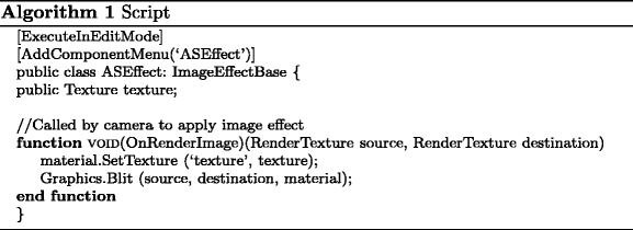
Fig. 9 
Steps 4 and 5. Assignment of the script and fragment to each camera
-
Step 5. The fragment shader is used from the script assigned to the main camera in the scene, that is, the one that will show the content for the users. The shader is also created in the Project Menu and it is assigned in the Inspector Menu (see Fig. 9). This shader is shown in Algorithm 2.


In Algorithm 1 ExecuteInEditMode makes a script to be executed in edit mode to have all these functions executed every frame while the editor is running, and not only in play mode. The AddComponentMenu attribute allows to place a script anywhere in the Component Menu. These two instructions are optional, but they help to manage better the scene in the editor. OnRenderImage is called after all rendering is complete and allows to modify the final content by processing it with shaders. Material.SetTexture function sets a named texture and Graphics.Blit copies source texture into destination render texture, enabling this destination render texture as active and drawing a full-screen quad.
The shader used for generating the interlaced content (Algorithm 2) works by assigning to the color components of all the sub-pixels of the device their corresponding color, computed from the information stored in the different renders (function getColor). This distribution will depend on the device used, involving different implementations of function getColorComponent. In Section 4 more details with the device that we have employed are given.
4 Experimental results
We have tested the different setups and configurations proposed in a 8-view 46-in. xyZ 3D LCD-display with lenticular lenses [36]. This device has horizontal parallax and its resolution is 1920 ×1080 Full HD. All the results have been tested in an Intel Core i7/ CPU 930 @ 2.80 GHz with an nVidia GeForce GTX 480 graphics card.
To store the renders using an eight-camera configuration, two distributions are recommended: a 3×3 mosaic (Fig. 10a) or a 4×2 mosaic (Fig. 10b). With the 4×2 mosaic the whole image is computed. With the 3×3 mosaic a part of the image is not used, but the aspect ratio is maintained in the stored renders. We can see an example of each disposition in Fig. 10a and b. In the 3×3 mosaic we repeat the ninth image, but it is discarded in the final interlaced composition.

a 3×3 mosaic and b 4×2 mosaic for a composition with eight cameras generated with a planar setup
Our implementation is based on the properties of the display used in this work. This device presents a sub-pixel distribution as shown in Table 1, following a slanted parallax barrier distribution. The slanted parallax barrier covers the display and defines particular light direction of each sub-pixel. Depending on the viewing angle and the distance of the observer from the display, most of the sub-pixels are masked. The structure of the optical filter defines certain correspondence map between sub-pixels and views.
The implementation of the shader used to access to the corresponding information in the composed image with the eight views in order to show the scene through the display is shown in Algorithm 3. In this shader the corresponding information for each sub-pixel is taken from the different renders, basing on the distribution shown in Table 1, which give us the view and color for each sub-pixel. getColorComponent function returns the information for the corresponding sub-pixel. The texture from which this information is extracted is computed.

Figure 11a shows the scene of the Fig. 10 interlaced with this shader. Figure 11b shows the same virtual world with an anaglyph system integrated in Unity, using the two central views. This enables the users to simulate the effect of these configurable parameters in a conventional display.

a Final interlaced image for the auto-stereoscopic display and b the same scene with an anaglyph system for any conventional display
Next, we explain the results achieved with the proposed setups (planar, cylindrical and hyperbolic) and their different configurations. In these experiments we have considered as initial values: D = 0.04, N = 0.8, F = 2000, R = 4 units, and \(\mathit{FOV}=60\), θ = 0.6°.
4.1 Planar setup
The planar setup imitates a planar distribution of a real rack of cameras. Therefore, the results obtained will be similar that the ones produced in a real world with cameras located in parallel. Next, we explain the effects of changing the parameters of this setup.
First, we can observe the influence of altering D (distance between cameras). As it can be appreciated in Fig. 12a, b and c, if this distance is increased, more separated images are obtained, producing a bigger three-dimensional sensation. Nevertheless, if the distance is augmented a lot, too much separated images are seen, and a double image sensation is caused.

Interlaced image with a D = 0.02 units, b D = 0.04 units and c D = 0.06 units
In any of the proposed setups we can change N and F (near/far clipping planes) and FOV (angle of the field of view of the cameras). We can see the effect of modifying N and F in Fig. 13a and b. Figure 13a shows the scene after moving N from 0.8 to 8 units. In Fig. 13b we have put closer the parameter F from 2000 to 20 units. We can appreciate that different regions of the virtual world are rendered when these planes are modified. This can help to avoid rendering regions with an excessive parallax.

a Interlaced image with a planar setup and the near of the camera to 8 units and b interlaced image with a planar setup and the far of the camera to 20 units
Varying FOV a zoom effect is generated, producing a zoom-in when the value of FOV is reduced. This can be appreciated in Fig. 14, where the parameter FOV has been changed from 60 to 30°.

Interlaced image with a planar setup and the field of view of the camera to 30°
4.2 Cylindrical setup
In the cylindrical setup the cameras look to the same point (the center of the cylinder), imitating the effect generated when we are focusing our vision in a specific object.
In this configuration we have put a white object in the center of the cylinder. We have changed the parameters θ (angle between cameras) and R (distance to the center of the cylinder). Figure 15 shows the image resulting of increasing the value of θ from 0.4 to 0.6°. The bigger are the values of θ, the more parallax is produced. However, if an excessive value is selected, it can be perceived a double image sensation in points far from the axis. If R is made larger the effect is similar than reducing the value of θ.

Interlaced image with a cylindrical setup with R = 4 units and θ = 0.6°
Increasing the value of θ causes a similar effect than modifying the parameter D in a planar setup. The difference is that when the offset increases, the distance between the cameras also augments, making larger the difference between the images. In order to establish a depth range with an acceptable parallax, it will help to modify the parameters N and F (such as shown in the previous examples).
If R is made larger the effect is similar than reducing the value of θ. In Fig. 16a, b and c the parameter R is modified. It can be observed that the region where the parallax is neutralized moves with the axis. Note that a change of parallax is produced where the objects are seen clearly. In these figures we have marked this region with a red circle.

Interlaced image with a cylindrical setup with a R = 4 units, b R = 8 units and c R = 10 units. θ has been set to 0.4°
The parallax perceived in an object depends on its depth in the scene, being the parallax in this configuration bigger in objects far from the axis. Thus, the content in far depths can vary a lot and more parallax than in a planar configuration can be produced. This can be solved by adapting FOV, N and F in order to fix a range with an acceptable parallax. The effect of each of these parameters is the same than the one obtained in the planar configuration. With the initial values of the parameters, F has to be set in a range of [100, 180] units. In Fig. 17 the parameter F has been set to 150 units. It can be appreciated that the objects far from the axis are not rendered, avoiding a double image effect. Thus, differing from the planar configuration, F cannot be considered as infinite, because a significant parallax is produced in objects far from the axis.

Interlaced image with a cylindrical setup with a R = 4, θ = 0.6 and F = 150
4.3 Hyperbolic setup
The hyperbolic setup can simulate the effect of rotating our head in a scenario. The main parameter that allows to generate different results of the scenario is the angle θ. In Fig. 18a and b we show the scene with θ = 0.6° and θ = 0.1°, respectively. Increasing R produces a similar effect than making the parameter θ bigger. Thus, we have fixed the value of R to 10 and changed the angle θ.

Interlaced image with a hyperbolic setup using a θ = 0.6 and b θ = 0.1°
We can appreciate that in this case small values of θ should be used in order to have reasonable visual results in the device (see Fig. 18b). Otherwise, assigning high values to the parameter θ (see Fig. 18a), an excessive horizontal parallax is obtained. This effect can be minimized by changing the values of N, F and FOV. The values of N and F help to fix a depth range with a reasonable parallax, as in the cylindrical setup. In the scene shown in the experimental results, setting θ to 0.3 degrees, F should be set around 150 units in order to avoid an excessive parallax in objects located at the background.
The variation of FOV can also help to avoid an excessive parallax when it is increased, because it makes the different renders to be more similar. However, if it is fixed to a high value, distortion in the final image can be produced. An example of this is shown un Fig. 19, where FOV = 150 units. This is because when FOV is increased the sides of the images are stretched more than the center.

Interlaced image with a hyperbolic setup with FOV = 150
5 Validation
We made a study with thirty participants (19 males, 11 females) from the Jaume I University of Castellón (Spain). The average age was 31.14 years (standard deviation of 7.15). The test shown in Appendix B was filled out with their answers. The goal of this test is the study of the visual perceptions, based on the values of the parameters chosen by the participants.
All the users first sat down at 4 m from the display. The experimental protocol was as follows: for all the proposed setups, we interactively changed each one of the parameters shown in the test (see Appendix B) and the participants were asked about the best visualization. These parameters were altered with keyboard events, which increased or decreased their values, following the order of the test. Participants could also change these values with the keyboard and navigate through the virtual world using the keyboard and mouse. Thus, we wrote in the test the values of the parameters for their optimal visualization of the scene. Later, they were asked with the questions shown in the test. They ordered in a ranking (with a score from 1 to 3) the three proposed setups for each question. Finally, they sat down at 2 m from the display and we changed again the parameters shown in the test for this distance. They were also asked about their perception feelings using the designed questionnaire.
Participants could move through the virtual world and watch at different parts of the scenario with a Full HD resolution (1920 × 1080). These zones of the scenario seen by the users had a range of [384,900, 1,300,000] polygons. The rendering performance was in range of [89, 138] frames per second, depending on which zones were watched. Thus, users were navigating through a high detailed scene in a interactive frame rate. We used the 8-view display commented at the beginning of this section in order to do the test. Thus, we employed an 8-camera configuration in the study. We also tested in Unity the setups increasing the number of cameras until 32. Interactive frame rates were also obtained. For a bigger number of cameras, multi-view acceleration techniques could be applied [19, 31].
Figure 20 shows the results of the answers of the participants. In its subfigures, it can be seen the median (the line inside the boxes), the 25th percentile (the lowest value of the boxes) and the 75th percentile (the highest value of the boxes). Moreover, the outliers are marked with crosses. Parameters were changed with the following precision steps: D: 0.001 units, θ: 0.01°, FOV: 0.5° and R: 0.1 units. N and F had initial values of N = 0.8 and F = 2000 units and were not varied in the tests, because they are useful to eliminate the double zones and we also wanted to know when the participants began to see a double image effect.

a Parameter FOV for each setup at 4 m, b parameter D for the planar setup at 4 and 2 m, c parameter θ for the cylindrical setup at 4 and 2 m and d parameter θ for the hyperbolic setup at 4 and 2 m
Figure 20a shows the values of FOV (y-axis) for each setup (x-axis). We can see that this parameter is similarly selected in any setup. The optimal value for the participants is not the same value, being a value near to the 25th percentile in the planar and hyperbolic cases. Figure 20b shows the values of the distance between cameras (y-axis) in the planar setup for both distances form the user to the display (2 and 4 m) (x-axis). It can be seen that distances between cameras when the user is located at 2 m should be smaller than distances between cameras at 4 m from the display. This is because the distance for the viewer recommended by the manufacturer is around 4 m. Thus, at smaller distances the separation between cameras should be decreased in order to not perceive double image sensation. Figure 20c and d show the angles between cameras (y-axis) at 2 and 4 m for the display (x-axis) in the cylindrical and hyperbolic setups, respectively. It can be seen that, similarly than in the planar case, participants chose smaller values for the angles when they were located near the display. With the cylindrical setup the optimal value is almost the 25th percentile value for the majority of users. With the hyperbolic setup the vast majority of participants chose values for the angle between cameras near to 0 when they located at 2 m from the screen.
Table 2 shows the means and standard deviations for each parameter in the three proposed setups. In the planar setup, we can note that the standard deviation value is similar than the mean value, that is, the values selected are in a wide range. FOV values were the expected, being near to 60 or 80.
In the cylindrical setup, the values of the angles are not so scattered (see Fig. 20c) than the values D in the planar case (see Fig. 20b). The values of an optimal R vary in a wide range. FOV values were also the expected in this case, as in the planar setup.
In the hyperbolic setup, θ values are smaller than in the cylindrical case. FOV values are similar than in the previous setups. The values of R differ more than in the cylindrical case, because the best visualization for the users usually tends to have high values of R. In this range of values the visualization was not almost affected, but the users tended to prove higher values looking for a visual change.
Table 3 shows the means and standard deviations for the parameters D in the planar setup and θ in the cylindrical and hyperbolic cases when the viewer is located at 2 m from the screen. This is due to the fact that depending on the distance of the viewer to the screen a different distance between cameras is required to avoid a double image sensation. From all the parameters considered previously in the camera setups only the parameters that affect to the distance between cameras should be varied in order to re-adjust the accommodation of the viewer. We can observe in this table that the values for these parameters used by the participants at 2 m to the screen are smaller than the values at 4 m for these parameters.
This study is related to visual aspects, such as, stereoscopic comfort zone, Panum’s fusion area, change of depth reproduction when changing viewing distance and excessive binocular disparity. Stereoscopic comfort zone is related to the values for the parameters selected depending on the location of the viewer. These parameters can also be altered in order to re-adjust the Panum’s fusion area depending on the location of the viewer. We can observe that the users needed to re-adjust the parameters D and θ, decreasing their values, because they were perceiving double image sensation. In a case where the same scene could be seen sharp at both distances with the same values of the parameters, more 3D sensation would be produced changing the viewing distance from 4 to 2 m. Finally, the binocular disparity is also related to the distances between cameras in a planar setup or angles and radius in the cylindrical and hyperbolic setups. We can observe in Fig. 20 that the biggest binocular disparity is caused with the hyperbolic setup when the participants were located at 2 m, because the images perceived by the users differ a lot when these angles are highly augmented. Thus, they selected the lowest values for the angles between the cameras in this case.
Finally, we have applied a Friedmann test [6], which follows a Fisher distribution, for analyzing significance of the answers of the participants to the questions of our test. This is a non-parametric technique to measure the significance of the statistical difference of the three setups that provide results on the same questions. We use a confidence level α = 0.05, 95 % confidence, to set up the critical value of the Fisher distribution for the three setups N S = 3 that appear in the comparative and 30 participants N P = 30, with degrees of freedom N S − 1 = 2 and (N S − 1)×(N P − 1) = 58, obtaining a critical value of Fisher distribution F(2,58) = 3.15.
Table 4 shows the results of the Friedmann test. This table also shows the average values of the score in the ranking for each question. They ordered in a ranking (with a score from 1 to 3) the more adequate setups for each question.
The order of the setups selected by the participants for the first question (best 3D sensation) was: cylindrical, planar and hyperbolic. In the second question (sharpest background) the order was: planar, cylindrical and hyperbolic. In the third question (most blurred sensation) the results were: hyperbolic, cylindrical and planar. In the fourth question (best sensation of rotation moving sideways) the results were: cylindrical, hyperbolic and planar. Finally, in the fifth question (favorite setup) the order was: planar, cylindrical and hyperbolic. In all the questions the result is conclusive because they have a positive Friedman test, which means that statistical differences are considered significant.
As we can see in the results, the majority of participants selected the planar setup as favorite. The biggest 3D sensation is not perceived by the planar setup, but the cylindrical one. Thus, producing the cylindrical setup the biggest 3D sensation, it is not the favorite for the users. This is due to the fact that in the cylindrical setup, objects far from the viewer can be seen more blurred than in the planar case. It can also be observed in the results that the planar setup is the one with less rotation sensation for the users. Rotating around the objects can help to have more immersion sensation in the scenario. The hyperbolic setup is the last one selected by the users, because it is the setup that produces the biggest astonishment feeling to the users. Note that the design of the display employed for the results was focused on a planar rack of cameras. For a better visualization of the cylindrical and hyperbolic setups, the used display should be designed thinking of these camera distributions.
6 Conclusions
In this paper we have presented a study about creating a multi-view system in a virtual world. To do this, we have developed a graphical system with several cameras, which post-process the renders generating interlaced content valid for auto-stereoscopic displays. Different camera setups have been proposed: planar, cylindrical and hyperbolic.
For each of the proposed setups, we can find an adequate configuration for specific auto-stereoscopic screen, an 8-view 46-inches xyZ 3D LCD-display. In this work we have explained general configurations that can be used in any kind of auto-stereoscopic devices, varying the number of cameras and the shader that interlaces the renders. Moreover, several configurable parameters for these setups have been considered and analyzed looking for a correct visualization.
The planar setup produces realistic and natural 3D sensations with an adequate distance between the cameras, simulating the result of a real rack of cameras distributed in parallel. In the cylindrical case, a bigger effect of rotation of the objects is perceived. The problem is that the higher is the distance from an object to the virtual cylinder, the bigger is the parallax. To minimize this effect, the near and the far clipping planes are employed to reduce the viewing depth range. With the hyperbolic setup, the sensation of viewing the scene turning horizontally our head is imitated. The main consideration in this setup is that the angle separation between the cameras has to be small, because the cameras see to different directions and the renders can significantly differ.
We have integrated this system in a powerful engine game, Unity 3D. A demo of this integration has been developed, in which all the described parameters can be modified. Thus, the effects commented in this work can easily be observed on it. It also demonstrates that the content is generated with an interactive frame rate.
Differing from previous works, a study with several participants about the parameterization of content generation for a correct 3D navigation in virtual worlds with different camera setups has been made. The goal of this study was the analysis of visual perceptions, based on the optimal values of the parameters chosen by the participants. The most chosen setup as favorite was the planar one. However, the biggest 3D sensation was produced in the cylindrical setup. The hyperbolic setup was the one that caused the most strange visual perception effects to the users.
As future work, due to the parallel nature of a multi-view system like the one developed here, we will consider the possibility of the parallelization and re-utilization of information with the latest advances appeared in the programming of the graphics hardware, like shaders or CUDA.
References
Cheng X (2007) Generation of layered depth images from multi-view video. In: IEEE international conference on image processing (ICIP ’07), pp 225–228
Chen H-J, Lo, F-H, Jan F-C, Wu S-D (2010) Real-time multi-view rendering architecture for autostereoscopic displays. In: Proc. of 2010 IEEE international symposium on circuits and systems (ISCAS), pp 1165–1168
DeCoro C, Tatarchuk N (2007) Real-time mesh simplification using the GPU. In: Proceedings of the 2007 symposium on interactive 3D graphics and games (I3D ’07), pp 161–166
Dogson N A (2002) Analysis of the viewing zone of multi-view autostereoscopic displays. In: Proc. of SPIE symposium on stereoscopic displays and applications XIII, pp 254–265
Fehn C (2003) A 3D-TV approach using depth-image-based rendering (DIBR). In: Proc. VIIP 03. Benalmadena, Spain (2003)
Friedmann M (1937) The use of ranks to avoid the assumption of normality implicit in the analysis of variance. J Am Stat Assoc 32(200):675–701
Fu H, Yao S-J, Li D-X, Wang L-H, Zhang M (2012) A real-time multi-view interlacing architecture for auto-stereoscopic 3DTV display based on FPGA. In: 2nd international conference on consumer electronics, communications and networks, pp 1569–1572
Gortler S J, Grzeszczuk R, Szeliski R, Cohen M F (1996) The lumigraph. In: SIGGRAPH’96, pp 43–54
Gumbau J, González C, Chover M (2008) GPU-based normal map generation. In: International conference on computer graphics theory and applications (GRAPP ’08), pp 62–67
Gumbau J, Chover M, Sbert M (2010) Screen space soft shadows. In: GPU pro, chapter 4, part VII
Hubner T, Pajarola R (2007) Single-pass multi-view volume rendering. In: IADIS, pp 50–58
Jarvenpaa T, Salmimaa M (2008) Optical characterization of autostereoscopic 3-D displays. J Soc Inf Displ 16(8):825–833
Jin Z X, Zhang Y J, Wang X, Plocher T (2007) Evaluating the usability of an auto-stereoscopic display. In: Proceedings of the 12th international conference on Human-computer interaction: interaction platforms and techniques (HCI ’07), pp 605–614
Juan M C, Pérez D (2010) Using augmented and virtual reality for the development of acrophobic scenarios. Comparison of the levels of presence and anxiety. Comput Graph 34(6):756–766
Lambooij M, Ijsselsteijn W, Fourtin M, Heynderickx I (2009) Visual discomfort and visual fatigue of stereoscopic displays: a review. J Imag Sci Tech 53(3):030201-1–030201-14
Levoy M, Hanrahan P (1996) Light field rendering. In: SIGGRAPH ’96 Proceedings of the 23rd annual conference on computer graphics and interactive techniques, pp 31–42
Luo J, Qin K, Zhou Y, Mao M, Li R (2010) GPU-based multi-view rendering for spatial-multiplex autostereoscopic displays. In: 3rd IEEE international conference, pp 28–32
Luo J, Qin K, Zhou Y, Mao M (2010) GPU rendering for tiled multi-projector autostereoscopic display based on chromium. Vis Comput 26:457–465
Marbach J (2009) GPU acceleration of stereoscopic and multi-view rendering for virtual reality applications. In: 16th ACM symposium on virtual reality software and technology, pp 103–110
Matusik W, Pfister H (2004) 3D tv: a scalable system for real-time acquisition, transmission, and autostereoscopic display of dynamic scenes. ACM Trans Graph 23(3):814–824
Mendiburu B (2009) 3D movie making: stereoscopic digital camera from script to screen. Elsevier, New York
Miksícek F (2006) Causes of visual fatigue and its improvements in stereoscopy. University of West Bohemia in Pilsen. Technical Report No. DCSE/TR-2006-04
Okoshi T (2010) Three dimensional imaging techniques, 2nd edn. Atara Press
Park J, Lee B, Hong H, Shin H (2006) Autostereoscopic multi-view 3D system using square subpixel structure. In: International display workshop, pp 1365–1366
Reiter D, Chen B (2007) LightShop: interactive light field manipulation and rendering. In: Proceedings of SI3D ’07, pp 121–128
Salmimaa M, Järvenpää (2008) Objective evaluation of multi-view autostereoscopic 3D displays. SID Symp Dig Tech Pap 39(1):267–270
Saygili G, Gurler G, Tekalp A M (2009) 3D display-dependent quality evaluation and rate allocation using scalable video coding. In: IEEE international conference on image processing (ICIP), pp 717–720
Shum H-Y, Chan S-C, Kang S B (2007) Image-based rendering. Springer, New York
Son J Y, Saveljev V, Kim J-S, Kim S-S, Javidi B (2004) Viewing zones in three-dimensional imaging systems based on lenticular. Appl Opt 43(26):4985–4992
Sorbier F, Nozick V, Biri V (2008) GPU rendering for autostereoscopic displays. In: 4th international symposium on 3D data processing, visualization and transmission (3DPVT’08)
Sorbier F, Nozick V, Biri V (2008) Accelerated stereoscopic rendering using GPU. In: The 16th international conference in central europe on computer graphics, visualization and computer vision (WSCG’2008)
Stendel D (2009) Autostereoscopic visualization of landscape—a research project. In: Screnk M, Popovich V V, Engelke D, Elisei P (eds) Coorp 2009—Competence Center for Urban and Regional Development. Sitges. TU Wien
Strecha C, Von Hansen C, Gool L V, Fua P, Thoennessen U (2008) On benchmarking camera calibration and multi-view stereo for high resolution imagery. In: IEEE conference on computer vision and pattern recognition, pp 1–8
Van Berkel C (1999) Image preparation for 3D-LCD. In: Proceedings of SPIE, vol 3639, pp 84–91
UNITY Game development tool (2012). http://unity3d.com
xyZ 3D Displays. Autostereoscopic 3D TV (2012). http://www.xyz3d.tv/
Zhang L, Tam W J (2005) Stereoscopic image generation based on depth images for 3D TV. IEEE Trans Broadcast 51(2):191–199
Acknowledgements
This work has been supported by the Spanish Ministry of Education and Science (TIN2009-14103-C03-01), Caja Castellón-Bancaja Foundation (P1.1B2009-45), Generalitat Valenciana (Project PROMETEO/2010/028, BEST/2011) and Consolider Ingenio 2010 (CSD2007-00018).
Author information
Authors and Affiliations
Corresponding author
Appendices
Appendix A: Demos and videos
In this appendix we present a tutorial to manage the demos attached with this paper, which present a virtual world in Unity3D with the planar, cylindrical and hyperbolic setups. Each one of these setups is presented in both auto-stereoscopic and stereo anaglyph representations.
Note that, as it is specified in the Unity documentation, the system and hardware requirements are Windows XP SP2 or later, Mac OS X Intel CPU & Leopard 10.5 or later and a graphics card with 64 MB of VRAM and pixel shaders.
The user can move through the scene using the cursor keys and turn around the scene with the mouse. All the studied parameters for each setup can be changed in the demos. The links where all the demos (both auto-stereoscopic and anaglyph of each setup) are located are the following:
-
Planar setup
-
Cylindrical setup
-
Hyperbolic setup
Additionally, we attach three different videos, showing the effect of varying all these parameters. In order to see better the behavior of each parameter, additional to the generated content we show the changes of the elements in the editor. These videos are located in:
Finally, the code of both the script and shader for Unity are also located in:
Appendix B: Test


Rights and permissions
About this article
Cite this article
González, C., Martínez Sotoca, J., Pla, F. et al. Synthetic content generation for auto-stereoscopic displays. Multimed Tools Appl 72, 385–415 (2014). https://doi.org/10.1007/s11042-012-1348-x
Published:
Issue Date:
DOI: https://doi.org/10.1007/s11042-012-1348-x