
Abstract
An electromechanical model for beam-like piezoelectric energy harvesters based on Reissner’s beam theory is developed in this paper. The proposed model captures first-order shear deformation and large displacement/rotation, which distinguishes this model from other models reported in the literature. All governing equations are presented in detail, making the associated framework extensible to investigate various piezoelectric energy harvesters. The weak formulation is then derived to obtain the approximate solution to the governing equations by the finite element method. This solution scheme is completely coupled, and thus allows for two-way interaction between mechanical and electrical fields. To validate this model, extensive numerical examples are implemented in the linear and nonlinear regime. In the linear limit, this model produces results in excellent agreement with reference data. In the nonlinear regime, the large amplitude response of the piezoelectric beam induced by strong base excitation or fluid flow is considered, and the comparison of results with literature data is encouraging. The ability of this nonlinear model to predict limit cycle oscillations in axial flow is demonstrated.
1 Introduction
The growing demand for small-sized and low-power electronic devices has led to a focused research effort on the technology of energy harvesting, by which a permanent and autonomous power generator is possible due to the extraction of a usable form of energy from ambient energy sources. The locally available energy sources include mechanical, thermal, solar energy, and so forth. They can be converted to electrical energy by a particular transduction mechanism of either fundamental physical interactions (e.g., Faraday’s law, from magnetic to electric) or material properties (e.g., piezoelectric media, from mechanical to electrical).
The interest of this study is piezoelectric energy harvesters (PEHs). One of the commonly investigated configurations of PEHs is a cantilevered beam made of a flexible and conducting material as a substrate layer with one (unimorph) or two (bimorph) piezoelectric layer(s) and a harvesting circuit attached. Similar laminated piezoelectric structures may also be used as sensors/actuators [1, 2], if the main focus is on control applications. For energy harvesting applications, the external excitation source can be a vibrating host structure [3,4,5] or fluid flow [4, 6,7,8,9]. In the latter case, significant attention has been paid to PEHs in axial flow [8, 10], where the effective and sustained extraction of flow energy is expected from limit cycle oscillations (LCOs). LCOs are large-amplitude self-excited and self-limiting vibrations resulting from, e.g., aeroelastic nonlinearity [10].
Accurate mathematical modeling is crucial to the design and optimization of PEHs. To date, lumped parameter [11] and distributed parameter [12] models have been developed in literature, and detailed discussion of issues and corrections of these models can be found in [13]. Among distributed parameter beam models, Euler–Bernoulli beam assumptions together with small displacement/rotation are most commonly used. It is well known that Euler–Bernoulli beam theory works perfectly for thin beams. However, for thick beams with low length-to-thickness aspect ratio, which leads to non-negligible rotary inertia effects and shear deformation [14], the Timoshenko beam theory would be a better choice. In 2010, Dietl et al. [15] proposed a Timoshenko beam model for a cantilevered bimorph PEH using the methodology of force and moment balance. Based on this paper, Zhu et al. [16] performed a more concrete analysis of the difference between the two PEH models. It is reported that at low length-to-thickness aspect ratio, the Euler–Bernoulli model tends to over predict the resonance frequency as well as the electrical output of the energy harvester. Energy methods are also adopted to build a Timoshenko beam model for PEHs, such as the work by Erturk [14]. More recently, Zhao et al. [17] also presented a Timoshenko beam model for a unimorph PEH. The unique contribution of this investigation consists in the solution: The steady-state Green’s function method and Laplace transform method are firstly used to obtain the closed-form solution to the electromechanical PEH model. All these models are geometrically linear and thus only feasible in small deformation regimes.
When it comes to large deformation regimes, for instance, harvesting energy from LCOs, as mentioned above, geometrical nonlinearity of the structure must be taken into account. The most popular nonlinear structural model in this field is the inextensible beam model [8, 10, 18, 19]. This model is derived from Euler–Bernoulli beam assumptions [20]. Therefore, it also suffers from the limitations indicated above in [16]. Further, since the above investigations [14,15,16,17] were only performed in the linear regime, more efforts are needed to explore the difference between PEH models based on Euler–Bernoulli assumptions and Timoshenko assumptions in the nonlinear regime.
Apart from analytic approaches with closed-form solutions generally used in the aforementioned research, the approximate solutions using the finite element (FE) method are also proposed, e.g., models based on Euler–Bernoulli assumptions by [6, 21, 22], a linear three-dimensional (3D) model by [23]. Finite element modeling is particularly valuable when studying the electromechanical behavior of complex PEHs because closed-form solutions are only available to PEHs with simple configurations [23].
This paper presents a nonlinear model of PEHs based on the geometrically exact beam theory [24]. With exact kinematic relations, this model incorporates first-order shear deformation and allows for large displacement/rotation. These two benefits are validated in the linear regime and the nonlinear regime, respectively.
2 General governing equations
In this Section, the equations governing the electromechanical behavior of a beam-like PEH are presented. For the sake of brevity, only a symmetric bimorph with a parallel-connection circuit is considered, but the basic idea of this method can be extended to consider PEHs in other configurations, as seen in the various numerical examples in Sect. 4 and the discussion on partial coverage of electrodes in Sect. 2.3.
2.1 Strong form equations
The geometrically exact beam theory dealing with the plane deformation of an originally straight beam [24] is used. The plane deformation may be stretching, bending, and shearing, which is linked to the axial strain \(\varepsilon \), curvature \(\kappa \), and shear strain \(\gamma \), respectively. The cross section of the composite beam is rectangular and assumed to perform only rigid body motions during the deformation.
The electrodes are assumed to continuously cover the entire top and bottom surfaces of the upper and lower piezoelectric layers. In this case, the electric potential on each surface does not change in the axial direction of the beam, which is also called the equipotential condition [23]. The mechanical effects and the resistance of the electrodes are negligible.

Configurations and unknown fields of the model (shown in orange) (color figure online)
A global Cartesian coordinate system \(O-XYZ\) is used to describe beam deformation, and the reference configuration \({\mathcal {A}}\) is for the undeformed beam while the current configuration \(\mathcal {A^*}\) is for the deformed beam. Directions \(1-2-3-4-5-6\) are introduced to facilitate the definition of direction-relevant quantities in what follows. The initially straight bimorph of interest is placed in the XZ-plane, and the piezoelectric layers are initially poled in 3-direction. \(o-xyz\) is the local coordinate system associated with the undeformed beam. For each layer, the axis through the geometric center of the cross section is selected as the x-axis. The position of an arbitrary point P on each layer after deformation is determined by the axial displacement u, the transverse displacement w, and the rotation angle of the beam cross section \(\psi \), as seen in Fig. 1a. The voltage output of the PEH, denoted by electric potential \(\phi \), is the voltage across the resistive load R in the circuit, as seen in Fig. 1b.
The mechanical variables u, w, \(\psi \) are spatially and temporally dependent while the electric variable \(\phi \) is only temporally dependent due to the equipotential condition. From the perspective of mechanics, on account of the feature that the bimorph has only one dominant dimension, it is advantageous with little loss of precision to use the fiber aligned with the x-axis to represent the corresponding layer. Accordingly, the variation of mechanical quantities along the beam thickness is not considered unless otherwise specified. As a result, a set of 10 variables is under consideration: nine mechanical unknowns \(U_m = \left\{ {u_i(x,t), w_i(x,t), \psi _i(x,t)}\right\} \) with \(\forall i \in \left\{ {u, s, l}\right\} \) and one electric unknown \(U_e = \left\{ {\phi (t)}\right\} \), where and hereafter the subscripts \((\cdot )_u, (\cdot )_s, (\cdot )_l\) indicate quantities related to the upper piezoelectric layer, the substrate structure, and the lower piezoelectric layer, respectively. When there is no need to distinguish the upper and lower piezoelectric layers, the subscripts \((\cdot )_u\) and \((\cdot )_l\) can be reduced to \((\cdot )_p\).
The three layers of the bimorph have the same length L and width b, and the thickness is denoted by \(h_u, h_s, h_l \) (\(h_u = h_l = h_p\) due to the symmetry). Both the piezoelectric and the substrate materials are assumed to have homogeneous mechanical properties with density \(\rho _u, \rho _s,\rho _l\) (\(\rho _u = \rho _l = \rho _p\) due to the symmetry). For this symmetric bimorph, the x-axis of the substrate structure coincides with the neutral axis of the composite beam.
2.1.1 Kinematic relations
According to the geometrically exact beam theory, the apparent deformation-induced strains (also called beam strain measures in classical beam theories [25], or more specifically, Reissner’s generalized strains [26]) in the reference configuration are
where \((\cdot )^{\prime }\) refers to the differential with respect to (w.r.t.) the local coordinate x. Because the fiber aligned with the x-axis of each layer is employed as the representative of the corresponding layer and thus \(z = 0\), the beam strain measures of interest can be written as
for \(\forall i \in \left\{ {u, s, l}\right\} \). In the above expressions, no assumptions are made for the rotation angle \(\psi _i\) in addition to that the beam cross section itself is rigid (equivalent to a first-order shear deformation theory).
For the piezoelectric layers, the non-negligible electric field \(E_3\) can be seen as the electric counterpart to the mechanical strain. \(E_3\) is assumed to be uniform across the thickness of the piezoelectric layers and is given in terms of \(\phi \) [15] as
It is pertinent to mention here that the relations between the electric field and the output voltage are dependent on the specific configurations of PEHs, see, e.g., for more details on the expression of \(E_3\) in [3] for the series connection case. Another point worth attention is that, as indicated in [27], Maxwell’s equations governing the electrodynamic behavior of a continuum usually refer to its current configuration, in which the physical quantities are measured. It means, Eq. (7) is stated w.r.t. the current configuration.
2.1.2 Constitutive relations
Linear material laws are used in this part to build the relations between the strain measures and the resultant loads for the PEH. For the substrate layer, the following linear relations in the reference configuration are commonly used [28]:
where the stress resultants \(N_s\), \(V_s\), and \(M_s\) are the normal force, shear force, and bending moment at the beam cross section, respectively; \(c_{Y,s}\) and \({c_{G,s}}\) are Young’s modulus or shear modulus; \(\nu \) is the shear correction factor; \(A_s\) is the area of the beam cross section; \(I_s\) is the second area moment.
For the piezoelectric layer, using the stress-electric displacement form of the linear constitutive equations for an XZ-plane Timoshenko beam model with the initial poling axis in 3-direction [29], the stress resultants in the reference configuration can be expressed as
and additionally, the non-negligible electric displacement, \(D_3\), can be regarded as the electric counterpart to the mechanical force, given by
for \(\forall i \in \left\{ {u, l}\right\} \). In Eqs. (9), (10), \(c_{Y,i}^E\), \(c_{G,i}^E\), \({\epsilon }_{33,i}^{S}\), \(e_{31,i}\) are material constants, and the superscripts \((\cdot )^E, (\cdot )^S\) denote that the constants are evaluated at constant electric field and constant strain, respectively. Using Eq. (7) to replace \(E_{3, i}\) in Eqs. (9), (10) by \(\phi \), the stress resultants \(\left\{ N_i, V_i, M_i, D_{3,i} \right\} \) in the reference configuration w.r.t. variables \(\left\{ \varepsilon _i, \gamma _i, \kappa _i, \phi \right\} \) with \(\forall i \in \left\{ {u, l}\right\} \) can be formulated. It is noteworthy that Eq. (7) is defined on the current configuration while Eqs. (9), (10) on the reference configuration, so the above naive replacement leads to inconsistency in the configurations. This inconsistency is inconsequential in small deformation settings, and may not matter even in some large deformation cases, which can be inferred from [8, 22], where this inconsistency is ignored in the theoretical model but good agreement with the experimental results is still achieved by the theoretical prediction results. To eliminate this inconsistency, one can refer to [27] to transform the electric quantities from the current configuration to the reference configuration.
Following the principle of virtual work as in [26], for \(\forall i \in \left\{ {u, s, l}\right\} \), the mechanical stress resultants in the current configuration are
If the linear constitutive models are not appropriate (e.g., when dealing with large strains), one can select other constitutive models such as examples given in [25, 26, 30].
2.1.3 Equilibrium relations
The equilibrium relations are established at the deformed segment (the current configuration) by the force balance in 1- and 3-directions as well as the moment balance about the segment center point, which are (see [24])
with \(\forall i \in \left\{ {u,s, l}\right\} \) in the dynamic context. In Eqs. (12), (14), \(f_{1,i}\), \(f_{3,i}\), and \(m_{5,i}\) are external distributed loads w.r.t. 1-, 3-, and 5-direction, respectively; the superscript \(\ddot{(\cdot )}\) means the second-order derivative w.r.t. time t, and \({(\cdot )}^{\prime }\) is still the derivative w.r.t. x.
For the piezoelectric layer, according to the differential form of Gauss’ law, the following equation:
holds for \(\forall i \in \left\{ {u,l}\right\} \) also in the current configuration. The area of the upper and lower surfaces of the piezoelectric layers after deformation is assumed to be identical to the initial area when integration of \(D_{3,i}\) is involved.
2.1.4 Boundary conditions
In line with the physical significance, the Dirichlet and the Neumann boundary conditions are called the kinematic and dynamic boundary conditions hereinafter, respectively. The mechanical kinematic boundary conditions are given by
where \({\bar{U}}_m\) is a prescribed displacement or rotation angle in different directions as shown in Fig. 2a, and \(\Gamma _m\) is the corresponding kinematic boundary. The electric counterpart to the mechanical displacement, namely \(\phi \) used in this work, is actually the difference between the electric potential (but not the electric potential itself) of the upper and lower electrodes attached on each piezoelectric layer, so no boundary values can be prescribed for \(\phi \), meaning there is no electric kinematic boundary condition.
The mechanical dynamic equilibrium boundary conditions are
for \(\forall i \in \left\{ {u, s, l}\right\} \), where \({\bar{F}}_1\), \({\bar{F}}_3\), \({\bar{M}}_5\) are prescribed external force or bending moment in different directions, \(\bar{[m]}\) and \(\bar{[J]}\) are the mass and the mass moment of inertia on the corresponding boundaries \(\Gamma _i^{1}\), \(\Gamma _i^{3}\), and \(\Gamma _i^{5}\), respectively, as depicted in Fig. 2b.
The electric equilibrium boundary conditions are
for \(\forall i \in \left\{ {u,l}\right\} \), where \({\bar{q}}\) is the prescribed free charge per unit electrode surface area.

Boundary conditions for piezoelectric layers
2.1.5 Initial conditions
The mechanical and electric initial conditions are given as the zeroth-, first-, and second-order time derivatives of \(U_m\) and \(U_e\):
where \(\alpha (x)\), \(\beta \) with the superscripts \((\cdot )^{\mathrm {O}}, (\cdot )^{\mathrm {I}}, (\cdot )^{\mathrm {II}}\) are a set of known time-independent functions. Only two time derivatives of \(U_m\) and \(U_e\) are required as the initial conditions for each unknown variable.
2.2 Coupling conditions
The three layers of the PEH are independent hitherto, and ten unknowns are concerned. By enforcing proper coupling conditions between them, the ten unknowns can be reduced to four: \(U = \left\{ {u_s(x,t), w_s(x,t), \psi _s(x,t), \phi (t)}\right\} \).
For the beam model under consideration, only the axial strain varies in the beam thickness direction as indicated by Eq. (1). Assuming that all strains at interfaces are continuous and the cross section of the whole laminate beam remains rigid during deformation, the following relations between mechanical unknowns of each layer can be obtained using Eqs. (1)–(3):
where \(C_k \; \text{ with } \; \forall k \in \left\{ {1,2,3,4}\right\} \) are integration constants. Not knowing the values of \(C_k\) is not problematic because only derivatives will be used in the final weak formulation. It should be noted that by this coupling the continuity of transverse shear stresses at interfaces computed from the constitutive laws is not satisfied. This issue may be alleviated by layerwise theories or zig-zag theories [31]. However, for thin and moderately thick laminated structures, the model resulting from the above coupling conditions is still able to predict adequately accurate global results, which is discussed further in Appendix A.
From Gauss’ law, the net charge in a parallel-connection circuit [15] is
According to the definition of electric current and Ohm’s law, the current in the PEH circuit, \(I_C\), has two different expressions as below,
Combining them, the coupling condition of the circuit is
2.3 Discussion on partial coverage of electrodes
For simplicity, in above derivation, full coverage of the electrodes is assumed. On account that the power output of PEHs is highly relevant to the electrode configuration due to the effect of strain nodes [32], it is beneficial here to make the above governing equations applicable to partially covered PEHs to track the state-of-the-art investigations [5, 8].
With the help of Eqs. (1), (10), and (15), the following exact expression of \(E_3\) can be formulated:
where \(C_5\) is the integration constant. Assuming that the coordinate of the interface between the covered and uncovered part is \(x = x_p\) and the value of \(E_3\) at the covered part is \(E_3 = E_p\), then the electric field \(E_3\) of the interface is \(E_3 = E_p = \left( -\frac{e_{31} \kappa (x)}{\epsilon _{33}^S}z+C_5\right) \Vert _{x =x_p, z=0}\), thus \(C_5 = E_p\). If we stick to use the fiber aligned with the x-axis as the representative of the corresponding piezoelectric layer, which means \(z = 0\) in Eq. (32), \(E_3\) is still spatially independent, and the value of \(E_3\) is identical to the value in the full coverage case. Therefore, all governing relations proposed above are still valid and only the integration interval has to be adapted to match the new length of the piezoelectric layer and the electrodes when deriving the weak formulation, which is presented in Sect. 3. This conclusion is consistent with the method used in other literature such as [5], where only the integration interval in the electrical equation is adapted when considering a bimorph with partial electrode coverage.
Another interesting point of the exact expression \(E_3(x, z)\) is that the distribution of \(E_3\) is not uniform throughout the thickness of the piezoelectric layer, which is in contrast to the assumption about the electric field in the previous text (this assumption is commonly used in literature, such as [3, 5, 15]). If the variation of \(E_3\) in the thickness direction is taken into account, the bending moment of the piezoelectric layer is \(M_p = c_{Y,p}^E I_p\kappa _p + \frac{e_{31}^2}{\epsilon _{33}^S}I_p\kappa _p\), so clearly the bending moment has one more term associated with the electric property of the material when compared with the simplified bending moment expression Eq. (9). Actually, if more complete constitutive laws for the piezoelectric materials are employed, as seen in paper [33], where the electric displacement in 1-direction is also involved, another term related to \(e_{15}\) will also be present. The two terms including \(e_{31}\) and \(e_{15}\) together are called the induced electric bending moment, and may not be neglected in some special cases [33].
2.4 Summary
In this Section, a unified framework including kinematic, constitutive, equilibrium relations as well as boundary conditions and initial conditions is applied separately to the different layers of a beam-like PEH; in particular, for the piezoelectric layers, the electric quantities are treated as electric counterparts to mechanical quantities. The different layers of a PEH and the attached circuit finally form one interdependent whole by the coupling conditions. For convenience, the governing equations presented in this Section are simplified to a certain extent, which, in addition to making the electromechanical model simpler, also provides the space to improve the model precision in the future. As indicated above, the potential directions include: to select appropriate constitutive laws when large strains exist; to make the reference/current configuration of electric quantities consistent; to fulfill the continuity condition of transverse shear stresses at interfaces; to incorporate the bending moment contributed by the electric property. Nonlinearities activated by physical excitation phenomena [34, 35] (the structural models of both are based on the Euler–Bernoulli assumptions) can be accounted for in the presented framework in order to study the overall behavior and performance of associated beam-like PEH systems.
3 Finite element model
Applying the method of weighted residuals to the equilibrium equations (12)–(15) and the boundary conditions (17)–(20), also introducing the electric coupling equation (31), with test functions matched with virtual work as \(\left\{ \delta {\varepsilon _i}, \delta {\gamma _i}, \delta {\kappa _i}, \delta {\phi }\right\} \), for \(\forall i \in \left\{ {u, s, l}\right\} \), yields the weak formulation of the electromechanical system as follows:
Equation (33) is consistent with the principle of virtual work (in the form of the principle of virtual displacement) with lines (33a–33e) devoted to the mechanical virtual work and lines (33f–33g) devoted to the electric virtual work. Line (33h) can be regarded as the method of Lagrange multipliers applied to Eq. (31). The last step to formulate the final weak formulation exclusively expressed with unknowns \(U = \left\{ {u_s(x,t), w_s(x,t), \psi _s(x,t), \phi (t)}\right\} \) is to impose the mechanical coupling conditions Eqs. (23)–(28) on Eq. (33). The final weak formulation is not given in this paper, considering it is only concerned with simple mathematical substitution. Hereafter, the subscript \((\cdot )_s\) linked to the displacement variables is omitted for convenience.
To obtain the approximate solution, the trial function for any unknown variable a(x, t) is introduced:
In Eq. (34), \(n_N\) is the number of ansatz functions, \(S_j^a(x)\) are ansatz functions of local or global support and fulfill the Dirichlet boundary conditions, \(q_j^a(t)\) are the associated displacement/voltage degrees of freedom, which are functions of time and are to be determined. In this work, the finite element (FE) method is employed, i.e., using ansatz functions of local support to discretize the electromechanical system in space. The semi-discrete matrix form can be written as:
where \(\mathbf {q}\) is the vector of displacement/voltage unknowns, \(\mathbf {q} = (q_u, q_w, q_{\psi }, q_{\phi })^T\); \({\mathbf {M}}_{lin}\), \({\mathbf {C}}_{lin}\), and \({\mathbf {K}}_{lin}\) are the mass matrix, damping matrix, and stiffness matrix associated with linear terms in Eq. (33), respectively; \({\mathbf {F}}_{nl}(\ddot{\mathbf {q}},\dot{\mathbf {q}}, \mathbf {q})\) is associated with nonlinear terms, and \(\ddot{\mathbf {q}}\), \(\dot{\mathbf {q}}\) in \({\mathbf {F}}_{nl}\) are induced by the coupling equations (23)–(28); \(\mathbf {f}\) is the vector of externally applied load. Nonlinearity associated with \(\ddot{\mathbf {q}}\), \( \dot{\mathbf {q}}\) can normally be neglected, because these terms include a factor \(\frac{h_s + h_p}{2}\), which, for typical beam structures, is much smaller than other length measurements.
4 Model validation
This section is devoted to validate the model proposed in Sect. 3. All numerical simulations are implemented using the FEniCS framework [36, 37]. The choice of function space is: continuous Galerkin of degree 2 for \(S_j^u(x)\) and \(S_j^w(x)\), continuous Galerkin of degree 1 for \(S_j^{\psi }(x)\), and \(S_j^{\phi }(x) = 1\). By this choice, shear locking effects are avoided [38]. The mass-proportional damping [23] is used in simulations when needed. The convergence of simulation results w.r.t. the number of finite elements and time step (in nonlinear problems) is examined for every example. All geometric and material parameters are given in Appendix B.
4.1 Linear regime
In this part, the linearized weak formulation of the model proposed in Sect. 3 is derived to facilitate the frequency domain analysis. Considering the main objective is to capture shear deformation effects, a numerical example aiming at thick beams (non-symmetric unimorph) given by [17] is implemented in addition to an experimentally validated example of thin beams (symmetric bimorph) given by [3].
4.1.1 Linearized weak formulation
If small deformation is concerned, the linear weak formulation of a symmetric bimorph in a parallel configuration can be achieved by linearizing the nonlinear kinematic relations Eqs. (4)–(6) and the coupling conditions Eqs. (23)–(28), and additionally, approximating the stress resultants \(\left\{ N^*, V^*, M^*\right\} \) to \(\left\{ N, V, M\right\} \):
with equivalent parameters being
In Eq. (36), the terms of boundary conditions and external loads are omitted for convenience. It can be found that the equivalent parameters Eqs. (38)–(42) are the same as those presented in [15], while Eq. (37) is special to the present formulation.
The expanded matrix form with sub-matrices resulting from FE discretization is
Equation (43) is a linear second-order ordinary differential equation (ODE) system that can be solved in frequency or time domain.
4.1.2 Numerical examples
Thin bimorph This example is from [3], where the single-mode electromechanical frequency response functions (FRFs) that relate the voltage output to translational base excitation are presented for a bimorph with a tip mass both in series and parallel configurations. All physical parameters in the numerical simulations are kept the same as the setup given in [3]. The thickness-to-length aspect ratio of the bimorph is \((2h_p + h_s)/L = 1.3\%\).
The response of voltage output \(\phi \) in the frequency domain for 3 different resistive load values (\(R = {1}~\hbox {k}\Omega \), \(R = {33}~{\hbox {k}\Omega }\), \(R = {470}~{\hbox {k}\Omega }\)) is computed and then compared with the analytic results, as shown in Fig. 3, where the results of both parallel and series (in this case, \(\vartheta = -\frac{1}{2}e_{31}b(h_s+h_p)\), \(C_0 = \frac{1}{2}\epsilon _{33}^{S}bL/h_p\)) configurations are given.
From Fig. 3, it can be seen that the numerical FRFs agree well with the analytic FRFs. Furthermore, the precise values of voltage output for different resistive loads at their respective resonant excitation frequencies are also compared, as shown in Table 1. Although discrepancies are observed between the voltage output from the present work and the experimental results from [3], the present work obtains almost the same results as that from the single-mode FRF given by [3] and the fully three-dimensional finite element model proposed by [23]. The fully three-dimensional model is apparently powerful when dealing with complicated PEHs, but the current beam model is particularly suitable for thin-walled PEHs because it saves much more computational resource compared to the three-dimensional model.

Numerical and analytic voltage FRFs in parallel and series configurations
Thick unimorph
This example is from [17], where the first natural frequencies of a Timoshenko beam model-based unimorph are computed using the Green’s function method and Laplace transform technique. The equivalent parameters of a unimorph can be obtained either directly from [12] or derived following the procedure presented in Sect. 2 with the neutral axis of the composite beam as the x-axis of the substrate structure.
Table 2 shows the comparison of the first natural frequencies when the unimorph is moderately thick with different thickness-to-length aspect ratio under short-circuit (\(R =1\times 10^2\,\Omega \)) and open-circuit (\(R =1\times 10^6\,\Omega \)) conditions. The analytic solutions are the closed-form solutions based on the steady-state Green’s function method and Laplace transform technology presented in [17], where data are available only under the short-circuit condition. The 1D FE data are obtained from the linear beam model Eq. (36), while the 3D FE data are obtained from a continuum-based three dimensional model. It can be seen that good agreement is achieved in all comparative cases. Therefore, at this point, it is persuasive to say that the current electromechanical beam model is capable of capturing shear deformation effects.
4.2 Nonlinear regime
In this part, two large deformation examples are implemented based on the nonlinear model proposed in Sect. 3. The first example is a highly flexible unimorph with a tip mass under strong base excitation that leads to an extreme deflection of the beam. The second example is a preliminary examination of [8], where encouraging prediction of the voltage output is achieved from a flow-driven bimorph although the fluid model is highly simplified. The generalized-\(\alpha \) scheme with parameters ensuring unconditional stability and second-order accuracy [39] is used to update fields in the dynamic system over time, and the nonlinear equations are solved by the Newton–Raphson method.
4.2.1 PEH under strong base excitation
This example is from [22], where the computational model is based on the Euler–Bernoulli assumptions under small strains and large deflections, and a decoupled solution scheme is employed, namely, solving the structural model firstly in a commercial FE program (ABAQUS) and then substituting the structural results into the circuit equation to obtain electric results. According to the specific circuit equation used in [22] and the circuit model of a unimorph with a resistive load R in [40], the circuit equation Eq. (31) in simulations is adapted to be
where \(C_p\) is the piezoelectric capacitance, \(\phi _{oc}\) is the open-circuit voltage across the piezoelectric layer, given by [22]
where \(L_p\) is the length of the piezoelectric layer (\(L_p = {31}\,{\mathrm{mm}}\)), \(h_c\) is the distance of the top of the piezoelectric layer from the neutral axis of the composite beam, and \(\psi (L_p)\) is the rotation angle of the beam at \(L_p\).
In the numerical simulations, all parameters of the setup are from Table 1 in Ref. [22]. Figure 4 shows the transverse displacement and the voltage at different excitation frequencies in the range 4.0–5.4 Hz when the base acceleration is \({4}\,\hbox {ms}^{-2}\). The reference data are taken from Fig. 9 in Ref. [22] (only data in the range 4.0–4.9 Hz are given), and the predicted data are the maximum steady responses in the simulations. Although there is a small phase shift between the reference and computed resonant frequency, i.e., from 4.64 Hz to 5.0 Hz, the values of both simulated tip displacement and voltage output coincide well with the reference data. The maximum tip displacement is about 25 mm, nearly 80% of the beam length (L = 32 mm). As for the voltage, the maximum value in simulations is 62 V, 7.5% lower than the reference voltage (67 V). This voltage discrepancy could be attributed to the different solution schemes used in our simulations and the reference paper [22]. When large deformation is concerned, the electromechanical models are normally highly nonlinear and thus difficult to obtain solutions, so decoupled solution schemes are commonly used, such as [8, 22, 41] (all of them use Euler–Bernoulli assumptions). In all numerical simulations of the present work, a completely coupled solution scheme is employed, i.e., solving the mechanical and electric unknowns simultaneously. By a numerical comparison, paper [22] indicates that the coupled scheme tends to predict lower voltage output than the decoupled scheme, especially when the electromechanical coupling is strong.
The dynamic response of this PEH at the resonant excitation frequency is shown in Fig. 5. The small saddles in Fig. 5c are caused by bending backward, which can be clearly seen from the deformed shapes of the unimorph (Fig. 5d). The unique bending backward phenomenon captured by nonlinear models in extremely large deflection cases is also reported recently in [41, 42].

Comparison of reference and simulated displacement and voltage at different excitation frequencies

Dynamic response of the PEH when the excitation frequency is 5 Hz and acceleration magnitude is \({4}\,\hbox {ms}^{-2}\)
Additionally, a numerical test is made to show the difference between the electromechanical results predicted by the linear model Eq. (36) and the nonlinear model Eq. (33) under the base excitation condition. The thin bimorph in a parallel configuration presented in Sect. 4.1.2 is used. To ensure this PEH appropriately flexible to undergo large displacement/rotation, the thickness of the substrate structure and the piezoelectric layers is reduced by half. All other parameters, including the damping ratio, remain the same. In this test, the resistive load is \({33}\,{\hbox {k}\Omega }\), and the frequency of the base excitation is the linear resonant frequency when \(R = {33}\,{\hbox {k}\Omega }\) (\({17.2}\,{\hbox {Hz}}\)). The comparison is given in Fig. 6, where the normalized tip displacement (NTD) is the percentage of the maximum steady tip displacement over the beam length. It can be seen that when the tip displacement is about 20% of the beam length, the linear displacement prediction starts to deviate from the nonlinear prediction; as to the power output, the deviation point presented by NTD is about 30%. Fig. 6 illustrates that for a PEH operating in a large deformation regime, e.g., in this particular example, when the NTD is larger than 30%, it is necessary to employ a geometrically nonlinear model to obtain accurate electromechanical response.

Comparison of linear and nonlinear PEH models under base excitation
4.2.2 PEH harvesting energy from axial air flow
In principle, to validate the proposed nonlinear model for flow-driven PEHs, e.g., harvesting energy from LCOs, an accurate fluid model for the axial flow is essential. Although considerable work has been accomplished in this area, as evident from the introduction sections of [8, 43], it remains difficult to mathematically express and to numerically compute the fluid force acting on the deforming structure. Hence, detailed fluid modeling is excluded from the scope of the current paper.
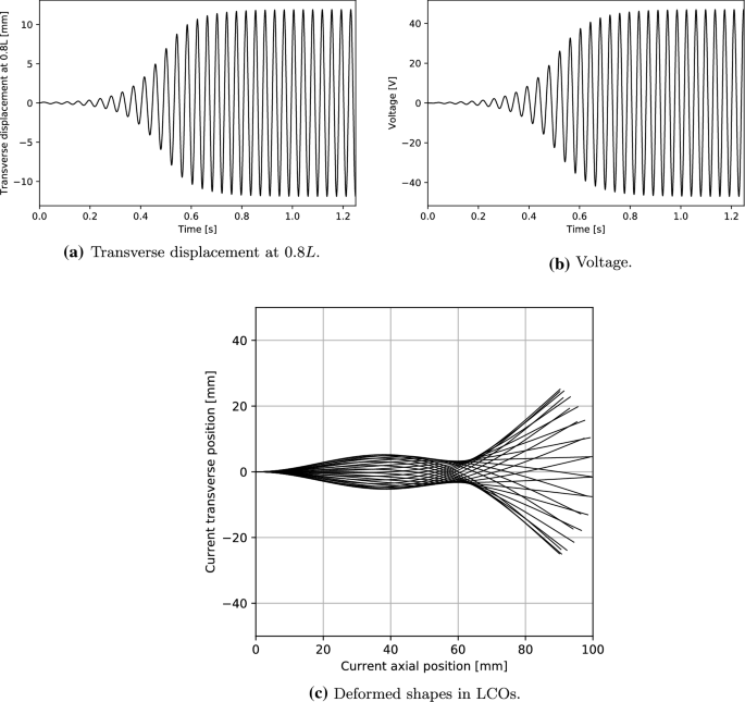
Considering that the electric output of PEHs is directly related to the structural deformation, the electric output can be determined for a given deformation pattern of the piezoelectric beam, no matter what (external force) induces this deformation pattern. Accordingly, the basic idea of the model validation in this case is to manufacture the deformation pattern present in [8] and then compare the voltage output. Reproducing the deformation pattern to a highly precise extent is only possible in a limited way due to the absence of a proper fluid model as well as other physical parameters. However, effective comparison can still be expected if the main characteristics of the deformation pattern are preserved.
It is reported in [8] that the modal content of the LCOs of the specimen is predominantly comprised of the first and second vibration modes; and the transverse displacement at 80% of the length from the clamped end is approximately 0.012 m (namely, \(w|_{x=0.8L} = {0.012}\,\text{ m }\)) when the airflow speed is \({34}\,\hbox {ms}^{-1}\) (data estimated from Fig. 7c in Ref. [8]). These two points are taken as the main characteristics of the deformation pattern to be reproduced. A simplified linear fluid model [43] is employed to manufacture the above deformation pattern, which reads
where \(\Delta {p}\) is the fluid pressure, \({\rho _{air}}\) is the airflow density, and \({U_\infty }\) is the free-stream velocity in x-direction.
Post-critical response of the PEH when the flow velocity is \({40}\,\hbox {ms}^{-1}\) and resistive load is \({10}\,\hbox {M}\Omega \)
A bimorph of continuous piezoelectric layer coverage in a series configuration with the same parameters as in [8] is used in the numerical simulations. Epoxy layers between the substrate and each piezoelectric layer are neglected. The external force model Eq. (46) is integrated in the nonlinear model Eq. (33), and an artificial initial velocity in the transverse direction \({\dot{w}}|_{t= 0} = 0.1x\) is applied to start the simulations. Figure 7 shows the electromechanical response of this bimorph when \({U_\infty } = 40\) \(\hbox {ms}^{-1}\) and \(R = 10\) M\(\Omega \). At this flow velocity, the flutter amplitude at \(x=0.8L\) is 11.9 mm (Fig. 7a), the modal form involves mainly the second-order vibration modes (Fig. 7c), and the maximum voltage output in LCOs is 47.0 V (Fig. 7b). When \(R = 100\) M\(\Omega \), the corresponding voltage is 50.9 V. In [8], the voltage output of the specimen is between 30 V and 40 V (data estimated from Fig. 8c of Ref. [8]) when \(w|_{x=0.8L}\) \(\approx \) 0.012 m, \(R \in \) [10 M\(\Omega \), 100 M\(\Omega \)]. Therefore, the identical magnitude of voltage to the reference data is predicted by the present model. The difference between the exact values can be explained by the roughness of the fluid model used in the current simulations. With such a simplified fluid model, the manufactured deformation pattern is not the same as that in [8].
In this flutter case, the solution convergence of Eq. (33) is observed to deteriorate severely with the longitudinal inertia term \({\rho _i} {A_i}\ddot{u}_i\delta {u_i}\). Since the motion in this direction is not of interest, this term is omitted in the above numerical simulations. It is also noteworthy that no physical damping (e.g., material viscous damping) or numerical damping from the generalized-\(\alpha \) scheme [39] is introduced into the above simulations. Therefore, the nonlinear restoring force, which is necessary to keep solutions bounded in time in the post-critical regime [44], as seen in Fig. 7, is due to the geometrical nonlinearity of the structural model. Contrasting this with a linear structural model such as Eq. (36), if the same linear fluid model Eq. (46) is used, the dynamic response of the system will be unbounded in time, and thus leading to non-physical results (Fig. 8).

Unbounded dynamic response of a linear PEH
Remark In the strict sense, the above validation is rather rough since the fluid model is highly simplified, but it is still clear that the proposed model has the potential to predict reasonable electromechanical response for a fluid-driven PEH. What’s more, the significance of introducing nonlinearity in the structural model for the fluttering case is elucidated by the comparison with a linear model for the same setup.
5 Conclusions
The beam-like configuration is commonly used in piezoelectric energy harvesting devices. This article proposes a model for PEHs based on the geometrically exact beam theory and appropriate solutions to the governing equations using the finite element method. With the help of the exact kinematics, this model is able to capture both shear deformation and large displacement/rotation. Various numerical examples covering the symmetric bimorph/non-symmetric unimorph, series/parallel configuration, thin/thick beams, and (strongly) base-excited/flow-driven PEHs are implemented, and good results are obtained, clearly exhibiting the broad applicability of the framework presented in the current work. In the nonlinear regime, the comparative investigation of a PEH under base excitation shows that geometrical nonlinearity should be considered when the tip displacement is over 30% of the beam length; and for the flow-driven PEHs, geometrical nonlinearity alone of the structural model is sufficient to provide the nonlinear restoring force necessary for the occurrence of limit cycle oscillations in axial flow.
References
Hwang, W.S., Park, H.C.: Finite element modeling of piezoelectric sensors and actuators. AIAA J. 31(5), 930–937 (1993)
Krommer, M., Irschik, H.: An electromechanically coupled theory for piezoelastic beams taking into account the charge equation of electrostatics. Acta Mech. 154(1), 141–158 (2002)
Erturk, A., Inman, D.J.: An experimentally validated bimorph cantilever model for piezoelectric energy harvesting from base excitations. Smart Mater. Struct. 18(2), 025009 (2009)
Bibo, A., Abdelkefi, A., Daqaq, M.F.: Modeling and characterization of a piezoelectric energy harvester under combined aerodynamic and base excitations. J. Vibrat. Acoust. 137(3), 031017 (2015)
Fu, H., Chen, G., Bai, N.: Electrode coverage optimization for piezoelectric energy harvesting from tip excitation. Sensors 18(3), 804 (2018)
Amini, Y., Emdad, H., Farid, M.: An accurate model for numerical prediction of piezoelectric energy harvesting from fluid structure interaction problems. Smart Mater. Struct. 23(9), 095034 (2014)
Orrego, S., Shoele, K., Ruas, A., Doran, K., Caggiano, B., Mittal, R., Kang, S.H.: Harvesting ambient wind energy with an inverted piezoelectric flag. Appl. Energy 194, 212–222 (2017)
De Marqui Jr, C., Tan, D., Erturk, A.: On the electrode segmentation for piezoelectric energy harvesting from nonlinear limit cycle oscillations in axial flow. J. Fluids Struct. 82, 492–504 (2018)
Ravi, S., Zilian, A.: Simultaneous finite element analysis of circuit-integrated piezoelectric energy harvesting from fluid-structure interaction. Mech. Syst. Signal Process. 114, 259–274 (2019)
Dunnmon, J., Stanton, S., Mann, B., Dowell, E.: Power extraction from aeroelastic limit cycle oscillations. J. Fluids Struct. 27(8), 1182–1198 (2011)
Roundy, S., Wright, P.K.: A piezoelectric vibration based generator for wireless electronics. Smart Mater. Struct. 13(5), 1131 (2004)
Erturk, A., Inman, D.J.: A distributed parameter electromechanical model for cantilevered piezoelectric energy harvesters. J. Vibr. Acoust. 130(4), (2008)
Erturk, A., Inman, D.J.: Issues in mathematical modeling of piezoelectric energy harvesters. Smart Mater. Struct. 17(6), 065016 (2008)
Erturk, A.: Assumed-modes modeling of piezoelectric energy harvesters: Euler-Bernoulli, Rayleigh, and Timoshenko models with axial deformations. Comput. Struct. 106, 214–227 (2012)
Dietl, J., Wickenheiser, A., Garcia, E.: A Timoshenko beam model for cantilevered piezoelectric energy harvesters. Smart Mater. Struct. 19(5), 055018 (2010)
Zhu, Y., Zu, J.W., Yao, M.: In ASME 2011 conference on smart materials, adaptive structures and intelligent systems (American Society of Mechanical Engineers Digital Collection), pp. 115–122 (2011)
Zhao, X., Yang, E., Li, Y., Crossley, W.: Closed-form solutions for forced vibrations of piezoelectric energy harvesters by means of Green’s functions. J. Intell. Mater. Syst. Struct. 28(17), 2372–2387 (2017)
Tang, D., Zhao, M., Dowell, E.H.: Inextensible beam and plate theory: computational analysis and comparison with experiment. J. Appl. Mech. 81(6), (2014)
Tang, D., Dowell, E.H.: Limit cycle oscillations of two-dimensional panels in low subsonic flow. Int. J. Non-Linear Mech. 37(7), 1199–1209 (2002)
Semler, C., Li, G.X., Paıdoussis, M.: The non-linear equations of motion of pipes conveying fluid. J. Sound Vib. 169(5), 577–599 (1994)
Lumentut, M., Howard, I.: Electromechanical finite element modelling for dynamic analysis of a cantilevered piezoelectric energy harvester with tip mass offset under base excitations. Smart Mater. Struct. 23(9), 095037 (2014)
Elvin, N.G., Elvin, A.A.: Large deflection effects in flexible energy harvesters. J. Intell. Mater. Syst. Struct. 23(13), 1475–1484 (2012)
Ravi, S., Zilian, A.: Monolithic modeling and finite element analysis of piezoelectric energy harvesters. Acta Mech. 228(6), 2251–2267 (2017)
Reissner, E.: On one-dimensional finite-strain beam theory: the plane problem. Zeitschrift für angewandte Mathematik und Physik ZAMP 23(5), 795–804 (1972)
Ortigosa, R., Gil, A.J., Bonet, J., Hesch, C.: A computational framework for polyconvex large strain elasticity for geometrically exact beam theory. Comput. Mech. 57(2), 277–303 (2016)
Irschik, H., Gerstmayr, J.: A continuum-mechanics interpretation of Reissners non-linear shear-deformable beam theory. Math. Comput. Modell. Dyn. Syst. 17(1), 19–29 (2011)
Humer, A., Krommer, M.: Modeling of piezoelectric materials by means of a multiplicative decomposition of the deformation gradient. Mech. Adv. Mater. Struct. 22(1–2), 125–135 (2015)
Auricchio, F., Carotenuto, P., Reali, A.: On the geometrically exact beam model: a consistent, effective and simple derivation from three-dimensional finite-elasticity. Int. J. Solids Struct. 45(17), 4766–4781 (2008)
Erturk, A., Inman, D.J.: Piezoelectric Energy Harvesting, pp. 345–346. Wiley, Hoboken (2011)
Stanton, S.C., Erturk, A., Mann, B.P., Inman, D.J.: Nonlinear piezoelectricity in electroelastic energy harvesters: modeling and experimental identification. J. Appl. Phys. 108(7), 074903 (2010)
Gherlone, M.: On the use of zigzag functions in equivalent single layer theories for laminated composite and sandwich beams: a comparative study and some observations on external weak layers. J. Appl. Mech. 80(6), (2013)
Erturk, A., Tarazaga, P.A., Farmer, J.R., Inman, D.J.: Effect of strain nodes and electrode configuration on piezoelectric energy harvesting from cantilevered beams. J. Vibr. Acoust. 131(1), (2009)
Schoeftner, J., Irschik, H.: A comparative study of smart passive piezoelectric structures interacting with electric networks: Timoshenko beam theory versus finite element plane stress calculations. Smart Mater. Struct. 20(2), 025007 (2011)
Gatti, C.D., Febbo, M., Machado, S.P., Osinaga, S.: A piezoelectric beam model with geometric, material and damping nonlinearities for energy harvesting. Smart Mater. Struct. (2020)
de Carvalho Dias, J.A., de Sousa, V.C., Erturk, A., Carlos Jr, D.M.: Nonlinear piezoelectric plate framework for aeroelastic energy harvesting and actuation applications. Smart Mater. Struct. (2020)
Fenics project. https://fenicsproject.org/
Logg, A., Mardal, K.A., Wells, G.: Automated Solution of Differential Equations by the Finite Element Method: The FEniCS Book, vol. 84. Springer, Berlin (2012)
Reddy, J.: On locking-free shear deformable beam finite elements. Comput. Methods Appl. Mech. Eng. 149(1–4), 113–132 (1997)
Chung, J., Hulbert, G.: A time integration algorithm for structural dynamics with improved numerical dissipation: the generalized-\(\alpha \) method (1993)
Elvin, N.G., Elvin, A.A.: A coupled finite element-circuit simulation model for analyzing piezoelectric energy generators. J. Intell. Mater. Syst. Struct. 20(5), 587–595 (2009)
Fallahpasand, S., Dardel, M.: Piezoelectric energy harvesting from highly flexible cantilever beam. Proc. Inst. Mech. Eng. Part K J. Multi-Body Dyn. 233(1), 71–92 (2019)
Farokhi, H., Ghayesh, M.H.: Geometrically exact extreme vibrations of cantilevers. Int. J. Mech. Sci. 168, 105051 (2020)
Eloy, C., Kofman, N., Schouveiler, L.: The origin of hysteresis in the flag instability. J. Fluid Mech. 691, 583–593 (2012)
Howell, J.S., Toundykov, D., Webster, J.T.: A cantilevered extensible beam in axial flow: semigroup well-posedness and postflutter regimes. SIAM J. Math. Anal. 50(2), 2048–2085 (2018)
Madabhusi-Raman, P., Davalos, J.F.: Static shear correction factor for laminated rectangular beams. Compos. B Eng. 27(3–4), 285–293 (1996)
Acknowledgements
The authors gratefully acknowledge the support of the Luxembourg National Research Fund under the PRIDE programme (PRIDE17/12252781).
Open Access
This article is distributed under the terms of the Creative Commons Attribution 4.0 International License (http://creativecommons.org/licenses/by/4.0/), which permits unrestricted use, distribution, and reproduction in any medium, provided you give appropriate credit to the original author(s) and the source, provide a link to the Creative Commons license, and indicate if changes were made.
Author information
Authors and Affiliations
Corresponding authors
Additional information
Publisher's Note
Springer Nature remains neutral with regard to jurisdictional claims in published maps and institutional affiliations.
Appendices
Appendix A
The aim of this part is to discuss the accuracy of the proposed beam model, which does not fulfill the stress compatibility between the layers due to the lack of warping displacements through the beam thickness. A static problem of a cantilevered laminate comprising one core layer and two face layers is investigated using the above beam model and a 2D continuum model. For simplicity, we choose only two different materials without piezoelectric effects, one for the core layer and the other one for the two face layers. The geometric and mechanical parameters are given in Table 3.
The governing equations for a 3D continuum are
where \({\mathbf {F}} = {\mathbf {I}} + \nabla {\mathbf {d}}\) is the deformation gradient tensor, \({\mathbf {S}}\) is the 2nd Piola-Kirchhoff stress tensor, \({\mathbf {E}}\) is the Green-Lagrange strain tensor, \({\mathbf {g}}\) is the body force vector, and \(\lambda , \mu \) are Lamé constants. In the 2D implementation, plane strain assumptions are used; in the 1D (beam) implementation, the equivalent parameter \((EI)_e\) in Eq. (38) is multiplied with the coefficient \(\frac{1}{1-\eta ^2}\) to obtain the appropriate bending stiffness.
We consider two laminates A and B, where each layer has a thickness of 0.01 m and 0.03 m, respectively, and thus the thickness-to-length ratio \(\alpha \) is 3% (case A) and 9% (case B). For both A and B, the core layer may be the strong material (\(c_Y = {100}\,{\hbox {GPa}}\)) or the weak material (\(c_Y = {20}\,{\hbox {GPa}}\)). For laminate A, the static body force is applied in the transverse direction (3-direction) of the structure as \({\mathbf {g}} = (0; {3\times 10^{7}})\,\mathrm {Nm}^{-3}\), while \({\mathbf {g}} = (0; 5\times 10^{8})\,\mathrm {Nm}^{-3}\) for B.
The deflection of the centerline of laminate A and B is obtained from an FE solution of the proposed beam model and the above 2D model. The results are shown in Fig. 9.

Comparison of the deflection computed from the beam model and the 2D model

Strain and stress distribution over the middle cross section of laminate B
In Fig. 9, the solid lines with circle markers are the 1D results when the shear correction factor (SCF) \(\frac{5}{6}\) is used. In Fig. 9b, the triangle and square markers indicate the SCF is \(\frac{1}{2}\) and 1, respectively. For laminate A, the difference between the 1D and 2D results cannot be distinguished, so only one SCF is employed. For laminate B, the SCF does influence the 1D results, although rather slightly in this case. This may be explained by the role of the SCF in the first-order shear deformation theory (FSDT). In general, FSDT fails to represent the high-order variation of transverse shear stresses through the thickness. To amend this, the SCF is introduced to match the global response obtained from FSDT with the elasticity solutions. For laminated structures, an ideal SCF could be computed using some sophisticated methods [45], where the configuration, geometry, and mechanical parameters are all of interest. Therefore, to further improve the accuracy of the beam model, an optimal SCF should be carefully determined case by case.
We also compare the strain and stress distribution over the middle cross section of laminate B when a weak core is used, as shown in Fig. 10. The axial strain for the 2D model is the axial component of \({\mathbf {E}}\), i.e., \(E_{11}\); for the 1D model, the axial strain is \(\varepsilon (x,z)\). Similarly, the shear strain is \(E_{13}\) in 2D and \(\gamma (x,z)\) in 1D; the axial and shear stresses in 2D are \(S_{11}\) and \(S_{13}\), respectively; the axial stress in 1D is \(c_{Y}\varepsilon (x,z)\), and the shear stress is \(\frac{c_Y\gamma (x,z)}{2(1+\eta )}\).
It can be seen that the proposed geometrically nonlinear 1D model predicts perfect axial strain/stress for the setup under consideration. This provides a justification for the observed adequately accurate global response of the 1D model, as demonstrated by Fig. 9, although the correct shear strain/stress is missing. This point may be illustrated from the perspective of strain energy. Defining the component of strain energy as below,
the percentage of axial strain energy \(W_{11}\) and shear strain energy \(W_{13}\) in the total energy \(W_\mathrm {2D} = W_{11} + W_{13} + W_{33}\) can be computed from the 2D model for a laminate with a weak core and various thicknesses, as shown in Table 4. For the 1D model, \(W_{11}\) and \(W_{13}\) can also be defined in a similar manner, e.g., replacing \(E_{11}\) by \(\varepsilon (x,z)\), and the total energy is \(W_\mathrm {1D} = W_{11} + W_{13}\). The proportion of shear strain energy increases monotonically as the laminate becomes thicker, but for all the given parameters, i.e., \(\alpha \leqslant 12\%\), the axial strain energy accounts for more than 95% share (referring to the 2D results). Hence, the accuracy of the model for global response is dominated by the prediction of axial strain/stress when the laminate is thin or moderately thick.
In summary, it is clear from the above discussion that the 1D model in this work can be used to obtain effective global response for common beam-like piezoelectric energy harvesters, where the structures are usually not very thick and the material parameters of the substrate and the piezoelectric patches do not deviate from each other too significantly.
Appendix B
Geometric and material parameters used in the numerical examples of this work are given in Tables 5, 6, 7, and 8, where the length is denoted by L, width by b, thickness by h, density by \(\rho \), Young’s modulus by \(c_Y\), Poisson ratio by \(\eta \), piezoelectric constants by \(d_{31}\) and \(e_{31}\), and permittivity by \(\epsilon _{33}^S\).
Rights and permissions
Open Access This article is licensed under a Creative Commons Attribution 4.0 International License, which permits use, sharing, adaptation, distribution and reproduction in any medium or format, as long as you give appropriate credit to the original author(s) and the source, provide a link to the Creative Commons licence, and indicate if changes were made. The images or other third party material in this article are included in the article’s Creative Commons licence, unless indicated otherwise in a credit line to the material. If material is not included in the article’s Creative Commons licence and your intended use is not permitted by statutory regulation or exceeds the permitted use, you will need to obtain permission directly from the copyright holder. To view a copy of this licence, visit http://creativecommons.org/licenses/by/4.0/.
About this article

Cite this article
Shang, L., Hoareau, C. & Zilian, A. A geometrically nonlinear shear deformable beam model for piezoelectric energy harvesters. Acta Mech 232, 4847–4866 (2021). https://doi.org/10.1007/s00707-021-03083-5
Received:
Revised:
Accepted:
Published:
Issue Date:
DOI: https://doi.org/10.1007/s00707-021-03083-5