
Abstract
The cleaning of large-scale indoor public spaces is currently performed by workers driving cleaning machines. However, labor shortages are becoming more acute, resulting in human labor being substituted with robotics solutions for the cleaning of large public facilities (e.g., airport terminals, stations, and underground commercial streets). With the rapid development of sensing and automation technologies, various types of large-scale cleaning robots have been proposed. However, due to difficulty in precise indoor positioning, cleaning along a preplanned path is still challenging for robots. Therefore, this study proposes a cleaning robot that maps large indoor spaces using laser scanning and can avoid obstacles. The chassis of the robot has two independent primary wheels and two auxiliary wheels as power and support; direct current (DC) is employed to power the vacuum cleaner and the robot’s drive motor, to prevent power loss due to DC–alternating current conversion. An indoor facility undergoes three-dimensional laser scanning, and the cleaning space is then mapped through matrix graphics; subsequently, a path is planned using the boustrophedon method. The distance to the wall, measured by the laser rangefinder, is employed as a reference for the correction of the robot’s movement. The powerful vacuum cleaner design of the proposed cleaning robot was experimentally confirmed as having the ability to suction trash. In addition, the proposed robot was shown to clearly identify obstacles through laser scanning and successfully avoid them during the cleaning process to complete the cleaning task along the preplanned cleaning route.
1 Introduction
The advancement of medical technology is granting extension to human life. However, heavy economic pressures such as education cost and mortgage payments have reduced the willingness of young people to have children. Developed countries are generally facing a low birthrate and aging population. The latest World Factbook compiled by the Central Intelligence Agency of the United States reported the total fertility rate, which is the total number of children born to a woman, of 224 countries in the world in 2017. Among all 224 countries, Taiwan had the third lowest (1.13). According to statistics calculated by the Department of Manpower Planning of the Council for Economic Planning and Development, Executive Yuan, the total number of newborns in Taiwan decreased from 329 581 in 1995 to 193 844 in 2017. The decreasing size of the workforce in Taiwan will inevitably lead to a serious labor shortage in the future. The demand of industry for equipment automation and robotics will gradually increase to solve this labor shortage problem (Roman 1993; Berglund et al. 2010).
Declining birthrates globally will gradually lead to a robotics-dominated world (Hagele 2016). Therefore, the robotics industry has become an emerging industry in which developed countries are competing to invest. According to the International Federation of Robotics (IFR) classification, service robots can be divided into two categories by their application area: personal/domestic service robots and professional service robots. Personal/domestic service robots include robots for home security, surveillance, performing domestic tasks, and assisting those with handicaps. Conversely, professional service robots comprise robots for professional cleaning, medical assistance, logistics systems, and national defense applications. According to a statistical report compiled by the IFR, the number of multipurpose robotic products sold worldwide was 254,000 in 2015 and 294,000 in 2016, indicating that robots are gradually replacing human labor. An increasing number of service robots are being applied in logistics, medical care, and agriculture. The output value of service robots in 2018–2020 is estimated to be US$77,490,000,000, implying that the robotics industry is growing at a double-digit pace (Hagele 2017).
The service robots currently on the market are mostly domestic cleaning robots, with the main function of cleaning indoor dust and small pieces of garbage, tasks normally completed by busy office workers. Driven by market demand, well-known and large manufacturers have begun investing in the domestic cleaning robot market; relevant products include the Roomba 960, manufactured by the iRobot Corporation (United States), XJ1807CB, TECO Electric & Machinery Co., Ltd. (Taiwan), VR65720LVMP, LG Electronics Inc. (South Korea), and VR20M7070WS, Samsung Electronics Co., Ltd. (South Korea). The technology employed in domestic cleaning robots has developed rapidly. The first Roomba was introduced in 2002, giving iRobot, its manufacturer, 16 years of experience in this application (Jones 2006). The obstacle avoidance function of the Roomba has progressed from front-end collision detection to using a 360° infrared camera for determining the distance to obstacles (the Roomba 960). The suction power of the robot’s suction device can be automatically adjusted according to the material that the robot detects it is cleaning, such as carpet, wood, or tiling; additionally, the AeroForce dust box provides high suction capacity through the turbine motor and vacuum suctioning power. The VR65720LVMP model developed by LG includes a dual-lens device that automatically calculates light source intensity, detects walls, and records images. By recording 30 images per second for constant comparison, the device enables accurate indoor positioning, resulting in highly effective cleaning in dark environments.
Due to problems such as insufficient battery life, positioning technology oriented to indoor use, and inadequate path planning efficiency (Čelan et al. 2016; Noertjahyana et al. 2017), domestic cleaning robots are still unable to meet cleaning demands in large public spaces. Therefore, most public spaces still rely on human-monitored cleaning machines (Fig. 1). Dirt accumulates rapidly in large public facilities such as airports, stations, and plazas due to the large crowds that pass through them every day. Thus, these public spaces must be cleaned multiple times per day. Cleaning companies usually manage more than one location; when numerous workers are required at each location a company is contracted to clean, problems such as labor shortage or the need for overtime emerge. Therefore, preventing cleaning staff shortages due to limited manpower and material resources is an essential topic for research on the cleanup of large public spaces.

Cleaning methods used in commercial cleaning services for large-scale public spaces
To solve cleaning staff shortage problems, the large manufacturers have invested in the development of public space cleaning robots. Lawitzky (2000) cooperated with Siemens AG to develop SINAS, a navigation system primarily for use in robots used to clean public spaces. The system employs a fiber optic gyroscope, a laser rangefinder (LRF), and 64 ultrasonic distance sensors. The LRF measures the distance of the robot to obstacles, and the ultrasonic distance sensors are used for scanning the floor and thus identifying passing spaces. Regarding positioning, the cleaning robot must first be manually operated once to explore the workspace, with the sensor recording values and path lengths detected by ultrasound. During cleaning, the robot calculates its current indoor position by comparing the features of its position with the recorded sensor and path length data. The SINAS has been tested in large indoor spaces such as fruit and vegetable markets and supermarkets. The test results indicated that the ultrasonic scanning technology cannot effectively detect obstacles before collisions with customers or objects occur. Nishidal et al. from Japan developed outdoor large-scale garbage recycling robots, namely OSR-1 and OSR-2 (Nishida et al. 2006). These robots have two mechanical arms, four laser scanners, and three video cameras. One of the cameras, known as the “Hand–Eye System”, is mounted at the center of the front paw of one of the robot’s mechanical arms, the job of which is to grip trash. The robot uses a laser scanner and video cameras to search for garbage in its path and calculate the distance to the garbage and its size; subsequently, the claws on the robotic arm are used to clutch the garbage and put it into a basket to complete trash pickup.
At Expo 2005 in Aichi, Japan, Panasonic Corporation exhibited an outdoor cleaning robot suitable for nighttime use called SuiPPi (Fig. 2a) (Hirukawa and Inoue 2007). SuiPPi is driven by dual-motor differential speed control, and cleaning operations are performed through the combination of a side brush and roller brush, which roll dirt from the ground into a dust box; the robot advances along the edges of a workspace first and then cleans the center of the workspace in boustrophedon manner (Bretl and Hutchinson 2013; Kong et al. 2006). Path correction is performed using a dead reckoning algorithm (Zampella et al. 2015; Reinstein and Hoffmann 2013), which employs predetermined reference points that are set up manually for the correction of current positioning results. To comprehensively examine the surrounding environment, the robot is equipped with three sensors: laser, 3D ultrasound, and RGB-D (depth) sensors. The robot starts decelerating when an obstacle within a certain distance is detected; the robot stops completely only when the distance is less than a threshold. Fuji Heavy Industries Ltd. also presented two outdoor cleaning robots, the RoboHiter RS1 (Fig. 2b) and RoboHiter T1 (Fig. 2c), at the Expo 2005 in Aichi (Phillip 2005). The RS1 sweeps the ground, whereas the T1 is a garbage-collecting robot that defines the trash can as a known location and regularly checks the amount of garbage it contains. Unlike the SuiPPi, the RoboHiter series employs the global positioning system and a laser scanner for path correction. When multiple RoboHiter robots are operating simultaneously, they can intercommunicate to allocate sweeping areas. At the 2009 International Robot Exhibition, Fuji Heavy Industries Ltd. released an autonomous office cleaning robot (Fig. 2d), which was designed to operate at night and could take the elevator to a designated floor without human intervention. At the 2011 International Robot Exhibition, Fuji Heavy Industries Ltd. released a further office cleaning robot equipped with new functionality: human–machine interaction. In the same year, Japan Airport Terminal Co., Ltd., and Figla Corporation jointly developed the F.ROBO CLEAN cleaning robot (Fig. 2e), which is larger than a general domestic cleaning robot. In addition to vacuuming, the F.ROBO CLEAN can also wax floors. Although its application scope is thus wider than that of a domestic cleaning robot, it is still inadequate for cleaning large-scale facilities.

Japanese cleaning robots
With scanning lasers becoming increasingly affordable and the advancement of sensing technologies, simultaneous localization and mapping (SLAM) has begun to be applied in indoor cleaning robots (Lee and Lee 2013; Hwang and Song 2011; Gutmann et al. 2012, 2013; Chen et al. 2014); this enables cleaning robots to perform cleaning tasks in unknown spaces. To solve the problem of indoor positioning, fuzzy control is employed for the correction of path-finding errors (Chung et al. 2015; Miah et al. 2018; Araujo and de Almeida 1999). However, studies using SLAM were mainly centered on the cleaning of outdoor public spaces or indoor domestic environments. Regarding the cleaning of large-scale indoor spaces (e.g., airport terminals and department stores), multiple challenges remain, such as indoor positioning, route planning, avoidance of collision with moving obstacles, and power management. Thus, the present study proposes a high-endurance robot with SLAM and path correction functions for large-scale indoor cleaning. The robot can plan cleaning paths and perform route correction for unknown large-scale indoor spaces. Use of such robots will mitigate the effect of future labor shortage due to a low birthrate.
2 System architecture
The principal five aspects of the system framework of the developed cleaning robot—the casing and mechanism, power supply system, vacuum device, SLAM, and cleaning route planning—are detailed as follows.
-
1.
Casing and mechanism: The chassis of the cleaning robot (Fig. 3) is made of 2.0-mm-thick galvanized iron sheets. The sheets are bent and folded to achieve the optimal strength at a given weight load; test results indicate that the sheets can withstand a load of 60 kg without being deformed. The casing is constructed with 1.2-mm-thick galvanized iron sheets. The battery holder containing four batteries is placed on the front end; the dust box and dust suction pipe are placed in the middle; and components such as the vacuum motor, industrial computer, and drive controllers are placed at the rear end to achieve weight balance over the chassis.
Fig. 3 
Chassis of the proposed cleaning robot

Three- and four-wheeled chassis generally have a large turning radius (Fig. 4). The axle design is based on that of self-balancing two-wheeled vehicles, with additional front and rear auxiliary wheels for stabilization (Fig. 5). Such design facilitates nimble steering when implementing boustrophedon and reduces the robot’s turning radius, even enabling the chassis to turn on the spot. Moreover, the robot adopts a sturdy steel skeleton to further improve its carrying capacity and protect the components housed within the casing.

Rotation radius of the three- or four-wheeled chassis

Bottom view of the chassis of the proposed cleaning robot
-
2.
Power supply system: the system contains lithium–nickel–manganese–cobalt (LiNixCoyMnzO2) batteries, the multivoltage converter, and the motor drivers. The design requirements for each component are described as follows.
-
(a)
Ternary batteries: To ensure the proposed robot has high endurance for cleaning tasks, a battery capacity enabling operation for a continuous 2-h period was designed. The maximum instantaneous discharge power of the battery does not exceed the 3C rate, and the cycle life should be approximately 300 (in this study, the experiment terminated when the battery capacity was lower than 80%). This standard is consistent with that adhered to in first-class battery factories. Fig. 6 shows the ternary lithium–nickel–manganese–cobalt battery used in the present study.
Fig. 6 
Ternary lithium–nickel–manganese–cobalt battery
-
(b)
Multivoltage converter: To provide various direct current (DC) voltages for the sensors, the motor drivers, and the DC motor power supplies, DC–DC conversion is performed using a single-chip integrated circuit (LM2596HV; Fig. 7). The voltage of the cascaded ternary batteries is decreased from 54.6 to 5 V, and the maximum output current is 2 A.
Fig. 7 
Diagram and photograph of LM2596HV integrated circuit for DC–DC conversion
-
(c)
Motor drivers: The selection of DC motor drivers for the primary and auxiliary wheels was based on the objective of simple maintenance. Brushless motor control circuits are complicated and expensive. Thus, a DC motor is employed, which is simple to control and inexpensive, with an operating voltage of 12–80 V (Fig. 8a) and an instantaneous output current of up to 340 A. The motor power of the vacuum cleaner is 500 W, and the driver board adopts a 6–90 V, 1000 W DC motor driver (Fig. 8b) as the driver interface.
Fig. 8 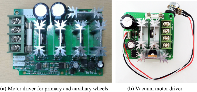
Motor drivers
-
3.
Vacuum device: A 48 V, 500 W DC industrial motor (Fig. 9a) is employed to control the vacuum cleaner, the cyclone vacuum canister dust box of which is the same as that in a Dyson (Fig. 9b). A strong suction effect is generated through centrifugal force induced by the cyclonic method (Fig. 9c). Dust, hair, fur, and the minute microbes and dust mites are thrown toward the bottom of the vacuum and then transported into the dust box. Thus, the motor is not contaminated and blocked due to trash suction, ensuring strong suction throughout the vacuum’s operation. More importantly, trash and air are separated, with the clean air exiting through the top.
Fig. 9 
Vacuum device
-
3.


Because of the substantial power required for the vacuum motor, which is approximately 500 W at 10 A, starting the motor driver at this current would blow the fuse or burn out the negative metal-oxide semiconductor component. Thus, this study designed a RC soft-start actuator (Fig. 10a) to reduce the starting current (Fig. 10b); the soft-start waveform lasts 5 s.

Design of the motor driver
-
4.
SLAM, and cleaning route planning: The proposed robot must scan unknown spaces, avoid obstacles, and plan cleaning routes. An unknown space is first scanned and mapped by a light detection and ranging (LiDAR) mounted on a rotating mechanism, and then receives a follow-up laser scan for precision mapping. Obstacles detected by the laser scan of LiDAR will be avoided by the robot during operation. To plan a route, the robot uses the boustrophedon method and the map information obtained through laser scan of the unknown space. Detailed descriptions of each part are described as follows.
-
(a)
Scanning of unknown spaces: To enable the LiDAR, a rotary mechanism was devised to give the LRF the ability to perform rotary scans (Fig. 11). In an unknown space, the cleaning robot should advance along the walls at a small distance. During this process, the rotary laser mechanism scans the interior of the space. Once the robot has contoured the space, an internal graphic of the space is acquired (Fig. 12a). Subsequently, the obstacle-free cleaning area can be identified as a group of matrix spaces (Fig. 12b). The matrix spaces in which the robot can effectively maneuver (pink areas) are retained, whereas the inaccessible ones are deleted from the map (blue areas). Finally, the matrix spaces that are feasible to clean are merged to obtain the cleaning area shown in Fig. 12c.
Fig. 11 
Rotary laser mechanism and its assembly
Fig. 12 
Mapping the area for cleaning in a space
-
(b)
Obstacle avoidance: The laser scan used in this system has a scanning range of 240° and 682 laser beams. The angle of variation of each beam is 0.352°. The data obtained from the laser scan can be used to calculate the distance between the robot and an obstacle ahead, which is then displayed in a graphic (Fig. 13). In Fig. 13, the white line at the bottom right is the start point of the laser scan, and the white line at the bottom left is the end point, resulting in a total range of 240°. The yellow lines indicate the distances measured by the laser beams; with 682 laser beams, a continuous pattern can be acquired. A shape appears when the laser scan detects an obstacle, as indicated by the green circle. No lines appear when the laser scan detects no obstacles within 4 m, as indicated by the purple circle (Fig. 13).
Fig. 13 
Display of the laser scanning procedure


When the distance measured by the LRF is D, the coordinates (X, Y) of the point can be calculated according to D and the angle of the laser beam. The radian (Ri) and coordinates (Xi, Yi) are calculated using
Due to the limitation of the cleaning robot’s mechanism, the scanning range for obstacle detection is set to 0°–180°. The number of laser beams after conversion is \(\frac{180}{240} \times 682 = 512\). The robot takes avoidance actions depending on the distance to an obstacle, which is determined by the 512 laser beams. Three distance ranges are established for this purpose (Fig. 14), and their corresponding rules of obstacle avoidance are as follows:

Obstacle avoidance range of the proposed robot
-
(i)
Green area (Dg): obstacles within this range do not affect the cleaning route of the robot. Thus, the cleaning robot need not perform obstacle avoidance.
-
(ii)
Orange area (Do): obstacles within this range might affect the travel path of the robot. Thus, the cleaning robot should perform obstacle avoidance.
-
(iii)
Red area (Dr): obstacles within this range will definitely affect the travel path of the robot; a collision might occur immediately. The robot stops advancing.
-
(c)
Clean route planning: The cleaning robot has numerous cleaning modes (Fig. 15) according to its movement pattern, such as the spiral mode, wall-following mode, hexagonal mode, bounce mode, and boustrophedon mode. These types of movement lack adaptability, resulting in the robot becoming trapped in corners and unable to reach the designated cleaning areas within a short time. When a cleaning robot is moving inefficiently or trapped, its movement mode must be switched. If a cleaning robot enters a narrow space that has only a single exit, such as a dead end or a narrow passage, the probability of it finding the exit through random collisions (bounce mode) is slim. If the wall-following is used in this situation, the probability of the robot exiting the dead end is increased. Figure 16 indicates that a two-wheeled cleaning robot can perform cleaning tasks in both cluttered and uncluttered areas without becoming stuck at a certain area. The strength of the two-wheel design is that the robot can rotate in place and thus does not need turning space.
Fig. 15 
Various cleaning modes
Fig. 16 
Cleaning areas


To enable efficient cleaning, the path illustrated in Fig. 17 can be obtained by applying the boustrophedon method to the areas feasible for cleaning (Fig. 12c). The path of the robot has width w; however, adjacent paths must overlap by a certain distance, defined as x (x < w), to ensure that the entire floor is swept (Fig. 18).

The boustrophedon method

Coverage area of the cleaning path
-
(d)
Path correction: Due to the mechanism of the cleaning robot, factors such as the terrain and dual-motor differential speed control might result in deviation from the designated path, and this deviation becomes progressively larger (Fig. 19a). In response to this problem, laser scanning is employed to correct the route deviation. When the robot advances directly to a wall, a deviation correction of its path perpendicular to the wall is conducted. In other words, when the robot approaches a wall, a turn to the right (or left) is performed first to enable laser beams to scan the wall, after which a parallel or perpendicular correction can be made according to the scanning results to correct the alignment with the wall. The LRF of the cleaning robot is used to correct the path of the robot within the surrounding walls. If the offset of the travel path exceeds d when the cleaning robot performs a boustrophedon movement, the robot controls the speed of both the primary wheels’ motors. In Fig. 19b, the cleaning robot decreases the speed of the left-hand primary wheel motor when an excessive offset occurs on the right (d), which causes the robot to advance in a leftward direction to correct the travel path. Therefore, in each task, under the condition of a preplanned cleaning path Di (Fig. 19c) and overlapping area of the cleaning path (x), as shown in (Fig. 19d), the equations which determine whether the right (R) or left (L) primary wheel of the cleaning robot has exceeded x as the robot is on odd- and even-numbered paths are as follows:
Fig. 19 
Travel path correction of the cleaning robot

Therefore,
where w denotes the width of the cleaning robot; a0 denotes the minimum distance between the cleaning robot and the wall; x denotes the overlapping width of the cleaning path; d is the allowed offset value; and i denotes the number of the path, ranging from 1 − n.
The movements of the cleaning robot mainly comprise stopping, advancing, and turning, and the communication protocols of the core controller for these movements are indicated in Table 1. There are 3 bytes in the protocol field, namely the header code, control code, and moving steps code. The header code is the starting position of the transmission data. Transmitted data that do not have header codes are invalid or incomplete; in such cases, no processing operation is performed. The control code has five movements—stop, advance, turn left, turn right, and reverse—with the commands being 0x55 and 0x01–0x04, respectively. Moving steps code is the number of steps in a movement. From 0x00 to 0xFF, a total of 256 bits represents 0–255 steps. The moving step for “stop” is 0x00 because no movement is required; any additional value signifies that the data are invalid. The detailed cleaning operation process is shown in Fig. 20.

Flowchart of cleaning movements of the cleaning robot
3 System testing
Regarding the chassis layout of the proposed cleaning robot, two 150 W motors are positioned at the front, with a speed reducer with a ratio of 1:26 for deceleration in sweeping. A 300 W, 1:26 speed reducer is configured at the middle as the drive motor. An LRF that can detect objects 4 m away is placed at the very front. Finally, two auxiliary wheels that rotate 360° are positioned at the front and back of the chassis to prevent the robot from tilting back and forth, which would lead to misjudgment of the laser scanner.
The Panasonic UR18650RX is used as the ternary lithium-ion battery (Fig. 6), which charges at 0.7 C and discharges at 5 C. The interior of this battery contains five batteries connected in parallel, and each parallel circuit contains 13 batteries connected in series. The voltage is 4.2 V × 13 = 54.6 V; the capacity is 2050 mAH × 5 = 10,250 mAH, which is approximately equal to 10 AH; and the maximum discharge current is 46 A. The most power-hungry component of the system is the 500 W vacuum motor, with a converted current value of I = P/V = 500 W/48 V = 10.4 A. The battery life is estimated to be (10,250 mAH/10.4 A) × 60 min = 57.6 min. Connecting two batteries in parallel provides approximately 115 min of battery life. The power consumption of a single drive motor with a 30% power drive is 2.0–2.5 A when the movement is linear, and the maximum consumption time of the two motors for the left and right primary wheels, when supplied by a single battery, is approximately 10,250 mAH/(2.5 A × 2) = 2 h. To meet the goal of 2-h continuous operation, the cleaning robot requires at least four lithium-ion batteries. In addition, the power consumption of an industrial computer is 12 V × 7 A = 84 W. An industrial-computer-dedicated battery (400 W) is used to power the industrial computer of the cleaning robot for 400 W/84 W = 4.7 h.
A field test was conducted in a long corridor in the basement of our department. A cardboard box was placed in the long corridor and acted as an obstacle. When the robot detected the obstacle, it stopped and rotated (Fig. 21a). Once the robot had rotated to an angle sufficient to evade the obstacle, it advanced (Fig. 21b). The obstacle was also placed on the left side of the robot. When the robot detected the obstacle on its left, it stopped and rotated (Fig. 21c). The robot started to advance and had dodged the obstacle once it had reached a sufficient angle (Fig. 21d).

Obstacle avoidance experiment
Before the boustrophedon method was implemented to determine a cleaning path, the designated cleaning space was scanned, as shown in Fig. 22a. The range and path available for sweeping were calculated after the scanning was completed (Fig. 22b). Figure 22 clearly shows the cleaning space and cleaning route. Two obstacles were each placed as the start and end points of the cleaning area, as displayed in Fig. 22b. In Fig. 23, two students were used to demarcate the start and end points, between which was a 10-m section for cleaning. The boustrophedon was adopted as the setting for cleaning path. The limited cleaning space not only allowed us to determine whether the robot was moving accurately but also ensured thorough cleaning.

Mapping and path planning of the cleaning space

Start and end points of the space for cleaning
After the cleaning space had been defined, the robot began to perform the cleaning task according to the planned route. The cleaning operation is shown in Figs. 24 and 25. In Fig. 24, the robot begins the cleaning operation. When it first approaches the wall, it stops advancing, as shown in Fig. 24a. Subsequently, the robot begins to turn left (Fig. 24b). In Fig. 24c, the robot has deviated to the right and has not aligned with the wall; the robot then turns left slightly to correct its path. In Fig. 24d, the robot has deviated to the left and has not aligned with the wall; the robot turns right slightly to correct its path. Figure 24e shows that the robot has aligned with the wall. As shown in Fig. 25, when the robot is aligned with the wall, it continues along the boustrophedon path, during which it maintains a path overlap of 1/3 its width to ensure proper cleaning.

Movement correction when the robot turns left to align with the wall

The proposed robot performing the boustrophedon path cleaning task
4 Conclusion
Most large-scale public spaces are cleaned by personnel from cleaning companies who drive large electric sweeping or brushing vehicles. However, the cleaning of large-scale indoor facilities must be performed during nonbusiness or late-night hours, and it is labor-intensive. This study uses laser scanning and an LRF to plan a cleaning route, avoid obstacles, and correct the path of a robot used to clean unknown spaces. The proposed robot can be continuously operated for approximately 2 h on a full charge, and the dual primary wheel design enables the robot to rotate in place. The scanning procedure, path planning, and obstacle avoidance functions of the proposed cleaning robot were successfully verified using experiments. In the future, cleaning robots can be employed in numerous public spaces to solve problems caused by labor shortages or late-night requirements.
References
Araujo R, de Almeida AT (1999) Learning sensor-based navigation of a real mobile robot in unknown worlds. IEEE Trans Syst Man Cybern Part B (Cybernetics) 29(2):164–178
Berglund T, Brodnik A, Jonsson H, Staffanson M, Soderkvist I (2010) Planning smooth and obstacle-avoiding B-spline paths for autonomous mining vehicles. IEEE Trans Autom Sci Eng 7(1):167–172
Bretl T, Hutchinson S (2013) Robust coverage by a mobile robot of a planar workspace. In: 2013 IEEE international conference on robotics and automation (ICRA), pp 4582–4587
Čelan V, Stančić I, Musić J (2016) Cleaning up smart cities—localization of semi-autonomous floor scrubber. In: 2016 international multidisciplinary conference on computer and energy science (SpliTech), pp 1–6
Chen P, Gu Z, Zhang G, Liu H (2014) Ceiling vision localization with feature pairs for home service robots. In: 2014 IEEE international conference on robotics and biomimetics (ROBIO 2014), pp 2274–2279
Chung H-Y, Hou C-C, Chen Y-S (2015) Indoor intelligent mobile robot localization using fuzzy compensation and Kalman filter to fuse the data of gyroscope and magnetometer. IEEE Trans Ind Electron 62(10):6436–6447
Gutmann J-S, Eade E, Fong P, Munich ME (2012) Vector field SLAM—localization by learning the spatial variation of continuous signals. IEEE Trans Robot 28(3):650–667
Gutmann J-S, Fong P, Chiu L, Munich ME (2013) Challenges of designing a low-cost indoor localization system using active beacons. In: 2013 IEEE conference on technologies for practical robot applications (TePRA), pp 1–6
Hagele M (2016) Robots conquer the world (Turning Point). IEEE Robot Autom Mag 23(1):118–120
Hagele M (2017) Double-digit growth highlights a boom in robotics (industrial activities). IEEE Robot Autom Mag 24(1):12–14
Hirukawa H, Inoue H (2007) Expo 2005 Robotics Project. In: Robotics Research. Springer, Berlin, Heidelberg, pp 567–580
Hwang S-Y, Song J-B (2011) Monocular vision-based SLAM in indoor environment using corner, lamp, and door features from upward-looking camera. IEEE Trans Ind Electron 58:4804–4812. http://ieeexplore.ieee.org/xpl/tocresult.jsp?isnumber=600567410
Jones JL (2006) Robots at the tipping point: the road to iRobot Roomba. IEEE Robot Autom Mag 13(1):76–78
Kong CS, Peng NA, Rekleitis I (2006) Distributed coverage with multi-robot system. In: Proceedings 2006 IEEE international conference on robotics and automation, pp 2423–2429
Lawitzky G (2000) A Navigation system for cleaning robots. J Auton Robots 9(3):255–260
Lee S, Lee S (2013) Embedded visual SLAM: applications for low-cost consumer robots. IEEE Robot Autom Mag 20(4):83–95
Miah MS, Knoll J, Hevrdejs K (2018) Intelligent range-only mapping and navigation for mobile robots. IEEE Trans Ind Inform 14(3):1164–1174
Nishida T, Takemura Y, Fuchikawa Y, Kurogi S, Ito S, Hiratsuka MON, Miyagawa H, Watanabe Y, Suehiro T, Kawamura Y, Ohkawa F (2006) Development of a sensor system for outdoor service robot. In: International joint conference on SICE-ICASE, pp 2687–2691
Noertjahyana A, Wijayanto IA, Andjarwirawan J (2017) Development of mobile indoor positioning system application using Android and Bluetooth low energy with trilateration method. In: 2017 international conference on soft computing, intelligent system and information technology (ICSIIT), pp 185–189
Phillip W (2005) Mobile Robots in Japan. DTI international technology promoter, pp 1–9
Reinstein M, Hoffmann M (2013) Dead reckoning in a dynamic quadruped robot based on multimodal proprioceptive sensory information. IEEE Trans Robot 29(2):563–571
Roman HT (1993) Robotic applications in PSE&G’s nuclear and fossil power plants. IEEE Trans Energy Convers 8(3):584–592
Zampella F, Ruiz ARJ, Granja FS (2015) Indoor positioning using efficient map matching, RSS measurements, and an improved motion model. IEEE Trans Veh Technol 64(4):1304–1317
Acknowledgements
The authors would like to thank The Ministry of Science and Technology (MOST) of Taiwan for supporting this research under project number MOST 106-2622-E-151-018-CC3
Author information
Authors and Affiliations
Corresponding author
Additional information
Publisher's Note
Springer Nature remains neutral with regard to jurisdictional claims in published maps and institutional affiliations.
Rights and permissions
About this article

Cite this article
Liao, TI., Chen, SS., Lien, CC. et al. Development of a high-endurance cleaning robot with scanning-based path planning and path correction. Microsyst Technol 27, 1061–1074 (2021). https://doi.org/10.1007/s00542-018-4048-2
Received:
Accepted:
Published:
Issue Date:
DOI: https://doi.org/10.1007/s00542-018-4048-2