
Abstract
Spurred by the rapid progress in sensor performance increase associated with contemporary miniaturization, many companies, organizations, and governments are interested in using new opportunities in civil remotely piloted aircraft system applications. Coupled with an enhancement in propulsion system performance as well as an optimized and well-matched aerodynamic design, flight envelope limits can be enlarged and new mission profiles arise. Due to these ambitions, resulting hybrid missions become more complex and individual with partially contradicting demands, such as vertical takeoff and landing capabilities, fast climb and cruise combined with a long-endurance loiter capability, and a hover capability up to altitudes of 5000 m. In order to fulfill the diverse mission requirements, several configuration concepts are investigated. The focus is laid on different propulsion system concepts where various technologies and energy storage types are considered, as well as their effects on the aerodynamic shape and the controllability of the configuration. The investigated concepts comprise tilt propeller, tilt ducted propeller, and tilt wing configurations with fixed and variable pitch propeller. Based on these studies, a feasible concept in the weight category of MTOW ≤150 kg was identified which accomplishes both the aerodynamic and performance demands and the controllability in all flight segments.
1 Introduction
Exemplary fields of civil application for vertical takeoff and landing (VTOL) remotely piloted aircraft systems (RPASs) start from surveillance tasks, followed by payload delivery jobs, through to manned-unmanned-teaming search and mark (SAM) tasks in mountainous areas. Especially the SAM capability in context of a search and rescue mission puts high requirements on an RPAS, both on flight performance and payload qualities. Use cases might be the search for avalanche victims [1, 2], which is very time critical because the survival probability sinks to only 50 % after 20 min [3], and the search for a crashed paraglider in an extensive territory in the European Alps [2]. Due to the partly contrasting flight performance demands, those missions are defined as hybrid and lead to new challenges in RPAS design.
The main objective is to identify an RPAS configuration which contains the capabilities to fulfill those hybrid missions successfully. In addition, requirements on environmental regulations and airspace integration are considered as well.
According to that, a market analysis of the latest VTOL RPAS designs was performed. Today far more than 600 RPAS configurations exist [4], and with expected expenditures of $89 billion in the next 9 years [5], the number will continue to grow. Regarding the hybrid missions, 13 completely conceptually different VTOL configurations are analyzed and compared with regard to mission performance, propulsion system, noise emissions, and stability and control. As reference, the classic helicopter configuration is used.
Subsequently, a new design concept is derived from a morphologic box which qualitatively compares the properties of the configurations. Initial design parameters are calculated by using the aircraft design chart equations from fixed- and rotary-wing design.
2 Requirements on VTOL RPAS
In contrast to conventional fixed-wing RPAS, the VTOL comprises the supplemental thrust demand for hover and also axial climb capability. Moreover, an easily maneuverable slow flight speed characteristic is required to switch between vertical and horizontal flight mode. Additionally, the detailed requirements to accomplish the two benchmark missions [2] are defined.
2.1 Mission
The point performance requirements are derived from both the avalanche victims and the missing paraglider mission [2]. Relevant parameters are as follows:
-
Flight speeds (V)
-
Flight altitudes (H)
-
Climb speeds (\(\dot{H}\))
-
Gust speed (w)
-
Sustained and attained turn rate (STR, ATR)
In Table 1, the respective highest value is defined for the design limits:
-
Specific excessive power (SEP)
-
Turn rates STR and ATR
-
Gust speed
-
Maximum flight speed and stall flight speed
-
Hover, axial climb, and transition.
The required climb speed of \(\dot{H}_{\text{SEP}} = 14\,{\text{m}}/{\text{s}}\) and the flight speed of \(V_{\text{climb}} = 42\,{\text{m}}/{\text{s}}\) are based on the mission performance of the avalanche victims’ scenario in order to reach the search area in less than 10 min. According to the ceiling of the European Alps, the maximum flight altitude \(H_{ \hbox{max} } = 5000\,{\text{m}}\) is demanded, and because of the distribution of search-and-rescue bases, a maximum flight speed of \(V_{ \hbox{max} } = 60\,{\text{m}}/{\text{s}}\) is essential to reach all destinations in time. For more detailed information, see Ref. [2].
Among those demands, there is also the mission performance requirement of a loiter capability of up to 6 h at \(V_{\text{cruise}}\) and \(H_{\text{cruise}} .\)
2.2 Payload
Since RPASs are flying sensor platforms, the aircraft design process focuses more on the interdependencies between sensor payload requirements and their effects on the aircraft itself (see Fig. 1). In order to complete the task of the SAM missions, the following abilities are demanded:

Sensor-aircraft interdependencies
-
Detect and identify persons and objects by day and night
-
Detect avalanche victims
-
Transmit the information via a data link to the ground control station or rescue personnel
-
Optional: communicate with victims on the ground
Therefore, electro-optical, infrared, or night vision sensors, and an avalanche transceiver are required. There is also a need for an antenna to transmit and receive data. Additionally, sensors for airspace integration with the ability to detect and avoid air-to-air and air-to-land are demanded.
The most important sensor parameters for aircraft design are as follows:
-
Weight
-
Performance
-
Power demand
-
Size
2.3 Environment
In the context of the defined goals by the European Commission for aircraft until 2020 [6], the objective is to develop an RPAS which satisfies all environmental requirements. This basically comprises that the propulsion system should reduce CO2 and nitrogen oxide emissions to a minimum or better avoid them completely using batteries, fuel cells, or hydrogen.
To meet the target of noise emission which should be decreased by more than 50 %, an optimized overall aircraft design is demanded, because a customized propulsion system integration can contribute to reduce the noise level.
2.4 Certification and airspace integration
A remotely piloted aircraft system consists of an unmanned aircraft which is piloted from its remote pilot station (RPS), an associated command and control data link as well as all other components specified in the type design. Depending on the type of operation and local regulations, the RPAS needs a type certificate and an airworthiness certification similar to every manned aircraft. Furthermore, a detect and avoid system is needed in order to perform a safe flight and to be integrated into non-segregated airspace [7].
2.5 Stability and control
The control requirement is divided into two parts: on one hand, stability and control of the aircraft and on the other hand, control of the aircraft via a data link by the RPS.
The aircraft should have static stable characteristics in all flight phases. The control margin should be as large as the worst gust condition defined. As a consequence, the control surfaces or mechanisms have to be designed for fixed-wing and rotary-wing flight mode.
The data link has to connect the RPAS with the RPS in the whole flight envelope. If this is not possible because of obstacles in the line of sight direction, a data link connection via a relay station must be ensured.
3 State-of-the-art VTOL RPAS concepts
From a manned aircraft point of view, today’s existing VTOL RPAS prototypes or design studies can still be described as unconventional aircraft (except helicopters). The 13 analyzed configurations differ in their propulsion system, in their method to generate additive thrust for hovering, axial climb, and the transition phase, as well as their takeoff weight which is not an exclusion criterion. Furthermore, it is important to point out that not all displayed configurations have reached the state of a flying prototype yet. It is obvious that the designs can be clustered into four categories: Fixed-wing configurations with additive thrust devices, rotary-wing configurations with additive wings, tilting aircraft, and helicopter. Most of the chosen concepts use the fixed-wing configuration base. The following analysis focuses on the propulsion and thrust concept, maximum takeoff mass (MTOM), and emissions and evaluates the overall design with respect to the defined VTOL RPAS requirements.
3.1 Fixed wing + additive thrust
This section includes eight different designs with a maximum takeoff mass of \(1.2\,{\text{kg }} \le {\text{MTOM}} \le 1180\,{\text{kg}}\).
-
(1)
Dos Samara
It is a configuration with a high wing aspect ratio and outboard wing panels together with a pusher propeller located at the fuselage aft. As can be seen in Fig. 2, the outboard panels spin as single rotors in order to produce additive thrust for the vertical flight phase. The propulsion system consists of one engine for the pusher propeller and two electric motors for the wing rotors. Hence, needed batteries and a rigid wing frame result in a MTOM = 66 kg. By using batteries instead of a combustion engine, not only the exhaust emissions, but also noise is reduced because only a reduced wing rotor tip speed is needed compared to the average helicopter. The concept promises reasonable mission performance but the stability and control during transition and vertical flight seems to be hard to handle, in particular with wind and gusts. Also asymmetrical loads can occur in the single-blade rotor shafts and induce vibrations into the wing [8].
Fig. 2 
Concept Sketch Dos Samara [8]

-
(2)
Tazenflugel
Similar to the Dos Samara concept, the Tazenflugel has a wing with a high aspect ratio. The main features are the propeller at the wing tips and separately titling wings to adjust the thrust vector. Figure 3 shows that it is a tail sitter configuration which means the aircraft has to tilt 90° between takeoff and landing and horizontal flight phases. The propulsion system is hybrid composed of one diesel engine turning an electric generator and additional batteries which results in a MTOM = 64 kg. The exhaust emissions are only reduced during takeoff while using the batteries, but the noise emissions are collectively low because of the low disk loading of \(\frac{\text{TOW}}{{S_{\text{P}} }} = 4 3. 1 1\; {\text{N/m}}^{ 2}\). The mission performance seems to be promising and also the noise characteristics can meet the goals but the stability and control in vertical flight mode with only two propellers and aileron deflection is critical in flight conditions with wind and gusts [8]. Also the sensor field of view would have to pan 90° in transition and vertical flight mode.
Fig. 3 
Tazenflugel with tilted wings [8]

-
(3)
Trifecta
Figure 4 displays the tricopter concept sketch in single propeller mode for horizontal flight. For takeoff and landing, the front propeller can be tilted 90° and two single-blade propellers on the tips of the horizontal tail provide additional thrust. The wing design is only focused on horizontal flight which leads to good mission performance. In order to supplement power, the hybrid propulsion system consists of a diesel engine and batteries. The takeoff mass is \({\text{MTOM}} = 120\,{\text{kg}}\) and contains a payload mass \({\text{PM}} = 27\,{\text{kg}}\). Similar to the Tazenflugel, the exhaust emissions are only reduced during takeoff. The noise emissions are unmodified, but in relation to the Dos Samara and Tazenflugel concept probably higher because of the three propellers. On the other hand, the stability and control in all flight phases is better because differential thrust and torque are in a triangular disposition and also ailerons can be used [9].
Fig. 4 
Concept sketch Trifecta [9]

-
(4)
Tilt duct UAV
In order to reduce noise and increase efficiency in the cruise phase, this design concept uses three ducted propellers. The two main ducted propellers are mounted at the wing tips and can be tilted as can be seen in Fig. 5. The third one is more like a ducted fan, because it is located in the fuselage between wing and tail and generates thrust only in z-direction. The wing tip ducts have a relatively big cross-sectional area, and despite short lever arms, they generate big bending moments which lead to a rigid wing frame and a takeoff mass of TOM = 103 kg. The propulsion system is composed of two two-stroke piston engines. Consequently, there is no reduction in exhaust emissions as it would be with a hybrid or electric propulsion system. The static stability margin of this configuration is 23 %, but the horizontal tail configuration is not optimized for high angles of attack in case of shadowing by the wing. The control in vertical flight mode is good because of the triangular thrust distribution. But in case of a loss of one of the main ducted propellers (one engine inoperative, OEI) neither in vertical nor in horizontal flight mode, a control is feasible [10]. In case of the previous noted configurations, a controlled horizontal flight would still be achievable.
Fig. 5 
Concept sketch Tilt Duct UAV [10]

-
(5)
Eagle eye
The Bell Eagle Eye is a tilt propeller configuration with one propeller at each wing tip, see Fig. 6. The propulsion system is a Pratt and Whitney PW200/55 turboshaft engine with a maximum takeoff rating of P = 478 kW. The mechanically synchronized propeller system is connected by a gearbox with the engine. The fuselage is divided into three parts with the objective that the front part can carry a payload mass of PM = 91 kg at a takeoff mass of MTOM = 1000 kg. The endurance requirement is sufficiently fulfilled, and other performance requirements are even exceeded. By using a kerosene engine, no significant reduction in exhaust emissions is expected and the noise will be similar to average twin-prop configurations. Due to the higher MTOM, the configuration demands propulsive power which hardly can be provided by batteries, so that these noise emissions have to be taken into account. In stability and control for horizontal flight, there is no difference identified to standard configurations. In vertical flight, the control is made by differential thrust and control surfaces like the aileron [11, 12].
Fig. 6 
Bell Eagle Eye [11]

-
(6)
Excalibur
This configuration stands out by its morphing wing concept. It has three ducted propellers and one tilting jet engine, which can be seen in Fig. 7, whereby two ducted propellers are included in extendable wing tips and one is in the front part of the fuselage. In case of horizontal flight, only the jet engine is used and the wing tips are retracted to a smaller wing area. The supplement power during takeoff is provided by batteries and electric motors. Because of the morphing ducted propeller concept combined with a jet engine, this RPAS has a rigid and heavy wing frame which leads to a takeoff mass of MTOM = 1180 kg. The mission performance cannot reach the requested objectives, instead this configuration has a good stability and control characteristic. Due to the jet engine, the emissions are relatively high [13, 14].
Fig. 7 
Excalibur during flight [13]

-
(7)
Wingcopter
This already flying VTOL configuration has four tilting propellers, mounted at the wing close to the fuselage, see Fig. 8. The propulsion system is fully electric and the aircraft has a takeoff mass of MTOM = 2.4 kg with a payload ratio of 16.7 %. The maximum endurance is about t = 20 min, and the exhaust emissions are reduced to zero [15]. In case of scaling up this concept, there could be some problems with the stability and control in vertical flight because of the relative big tail area and the corresponding long lever arm in flight conditions with gusts and crosswind. Moreover, a pure electric propulsion system for aircraft with MTOM ≥100 kg is a challenging objective.
Fig. 8 
Wingcopter [15]

-
(8)
Tricopter
This is the smallest and lightest configuration with a takeoff mass of MTOM = 1.2 kg. Figure 9 shows that it is a blended wing body configuration with a delta wing planform and an aspect ratio greater than five. The propulsion system consists of three electric-driven propellers. Two counter-rotating propellers are located in front of the configuration and can be tilted from −5° to 90°. The third one is mounted in the middle right behind the trailing edge. Its main thrust direction is into the z-direction for vertical flight. Due to the electric-driven propellers, the exhaust emissions are zero and the triangular thrust and torque distribution provide good stability and control in vertical flight [16].
Fig. 9 
Tricopter [16]

3.2 Rotary wing + additive wing
This section contains three concepts in different mass categories which were already flying for test purposes.
-
(9)
X-50A
This configuration is also called “Canard Rotor/Wing” demonstrator which has a rotor for vertical flight that can be stopped and serves as wing in horizontal flight mode. Figure 10 displays the X-50A with the stopped rotor in cruise flight mode. The propulsion system contains a turbofan engine which provides direct thrust to the nozzle in the aft fuselage or to the valves in the rotor blade tips, which eliminates the need of a transmission or an anti-torque system. The takeoff mass is MTOM = 662 kg. Exhaust emissions cannot be reduced due to a non-existing hybridization and the mission performance requirements are probably not fulfilled. For stability and control in horizontal flight both, canard and tail are used [17, 18].
Fig. 10 
X-50A [18]

-
(10)
Project zero
Project Zero is a blended wing body configuration with two tilting ducted propellers integrated in the middle of the wing, see Fig. 11. The demonstrator propulsion system consists of batteries and two electric motors without a transmission or swashplates. The emissions are reduced, and stability and control in vertical and horizontal flight is good. If the design mission consists of a high hover ratio, the outer wing tips can be disassembled. In order to increase the mission performance, a hybrid propulsion system consisting of a diesel engine and batteries is also under development [19].
Fig. 11 
Project Zero [19]

-
(11)
Quad tilt wing
The idea of this concept is to combine the quadcopter control capabilities with the mission performance of a fixed-wing aircraft like the Wingcopter. Figure 12 visualizes that this RPAS is a twin wing configuration with two propellers on each wing. The front and rear wing is divided into left and right wing section and can be tilted independently. Additionally, a T-tail exists for stability and control in horizontal flight. The propellers are all driven by electric motors and batteries so that no exhaust emissions are generated. The noise emissions are higher than with tilting propellers. The quadcopter thrust and torque distribution are assumedly the most stable and controllable configuration for vertical flight. On the other hand, the mission performance is lower than for a single wing concept [20].
Fig. 12 
Quad Tilt Wing [20]

3.3 Tilting aircraft
A tilting aircraft has no rotating or tilting components except the rotation of the motor and propeller. This means the entire aircraft is tilted between horizontal and vertical flight phase.
-
(12)
T-wing
This RPAS is a tail sitter configuration with a canard and a wing at the aft fuselage. The wing has a rectangular planform with two mounted propellers and respectively one vertical tail in the propeller airflow. Because of no tilting assembly, the whole aircraft tilts in transition flight phase. The propulsion system consists of two two-stroke engines and the aircraft has a takeoff mass of MTOM = 30 kg. Consequently, the emissions are high in relation to electric or hybrid propulsion systems, and neither the flight performance nor the stability and control in challenging environmental conditions seem to be sufficient in order to fulfill the stated requirements [21] (Fig. 13).
Fig. 13 
T-Wing in takeoff position [21]

3.4 Helicopter
Helicopters are the most common VTOL aircraft and are used as a kind of technology and performance reference.
-
(13)
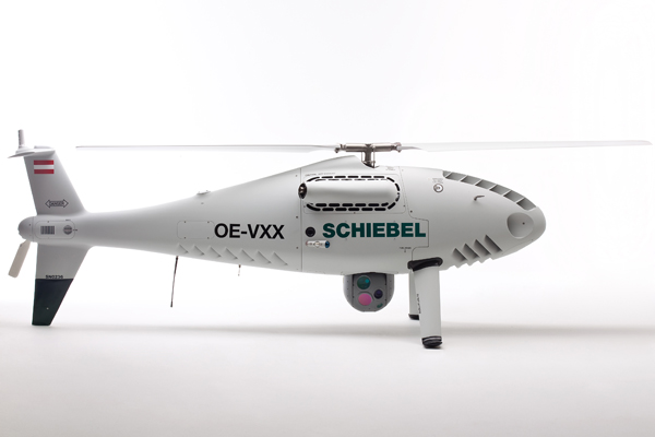
Schiebel CAMCOPTER S-100
Figure 14 displays the Schiebel CAMCOPTER S-100 which is a rotary engine powered helicopter RPAS. In addition to the tail rotor, there is also a T-tail with a big vertical tail providing sufficient stability and control characteristics. The mission performance covers the stated requirements but unfortunately a reduction in exhaust emissions using batteries is not achieved. The MTOM = 200 kg includes a maximum payload mass of PM = 50 kg which offers the possibility to integrate a required detect and avoid system in order to fly in non-segregated airspace [7, 22]. The cruise performance efficiency is lower compared to a fixed-wing aircraft, which is a general characteristic of helicopters.
Fig. 14 
CAMCOPTER S-100 [23]

3.5 Summary
Due to the demand of an increase in helicopter mission performance, fixed-wing concepts with additive thrust devices seem to be the most promising approach according to qualitative analysis. This also reflects the number of concepts which have been developed in the last years. A summary of available technical data is presented in Appendix Table 3.
3.6 Morphologic box
Derived from the analysis of the listed configurations, a morphologic box (see Table 2) is defined. On the horizontal, all features and on the vertical, all evaluated characteristics as well as the assignment to the examined RPAS are displayed. The evaluation standard refers to a propeller-driven fixed-wing configuration with a kerosene engine. Hence, the evaluation follows this pattern, starting from an improvement (+ +) through to a deterioration (− −):
The applied acronyms are as follows:
- F :
-
Features
- TW:
-
Tilt wing
- MW:
-
Morphing wing
- TP:
-
Tilt propeller
- DP:
-
Ducted propeller
- WP:
-
Wing propeller
- SP:
-
Supplemental propeller
- TA:
-
Tilt aircraft
- GF:
-
Green fuel
- C :
-
Characteristics
- SW:
-
Structure and weight
- VP:
-
Vertical flight performance
- HP:
-
Horizontal flight performance
- H:
-
Hovering
- SC:
-
Stability and control
- P:
-
Payload
- EE:
-
Exhaust emissions
- NE:
-
Noise emissions
- AC :
-
State-of-the-art VTOL RPAS
Neglecting the features with a strong characteristic deterioration (− −), five applicable features remain whereby assets and drawbacks have to be analyzed carefully with regard to the requirements.
A tilt wing aircraft improves the flight performance in all flight modes but on the other hand, possible payload weight decreases and the noise emissions in transition flight mode are bigger compared to a tilt propeller configuration with the same disk loading. This is because of the bigger surface area which has to be tilted in the air flow. Additionally, a tilt propeller configuration enhances the stability and control characteristic. The third possibility for changing the thrust vector’s direction is tilting the whole aircraft. A disadvantage of this method is a bad stability and control quality. As a consequence, applying tilt propellers is the most promising method generating lift for vertical flight. If furthermore one or more of those propellers are only supplemental propulsive devices, the payload weight can be increased because of smaller and consequently lighter motors applied only for the vertical flight phase. Moreover, the horizontal flight performance is decoupled from the vertical flight performance. Finally, a green or hybrid propulsion system can decrease the exhaust emissions and in case of a well-developed overall design the noise emissions as well.
4 Conceptual design study “Janus”
Based on the market analysis of latest VTOL designs and the utilization of the morphologic box, a conceptual design study is done. It comprises an initial concept presentation, a performance estimation using an aircraft design chart, and the generic description of the stability and control principles.
4.1 Concept
The conclusion from the morphologic box is that tilting propellers and supplemental propellers for vertical flight phases are the most promising features for a VTOL RPAS with focus on the enhancement of mission performance. With regard to the challenging weather conditions for RPAS in context of search-and-rescue missions in mountainous areas, a quadcopter configuration seems to have the best stability and control characteristics in vertical flight. On the other hand, in horizontal flight, a fixed-wing configuration with conventional horizontal and vertical tail layout is the best. The main idea is to combine all those aspects in one aircraft. Figure 15 shows the top view draft of the new concept.

Top view draft
Most important characteristics of this concept are as follows:
-
Split fuselage
-
Mid-wing configuration
-
High wing aspect ratio
-
Two tilting propellers in the fuselage noses
-
Big vertical tails for OEI
-
Two horizontal tails which are supplemental rotors
-
Modular payload concept
A split fuselage provides the possibility to have a two-propeller configuration in horizontal flight mode and even more important a four-rotor configuration in vertical flight. The two supplemental variable pitch rotors are mounted on top of the vertical tail (VT) and are horizontal tails (HT) concurrently. With regard to the mid-wing configuration, the HTs are arranged above the wing (see Fig. 16) and avoid the risk of a deep stall in case of flying with high angles of attack in transition flight phase.

Side view draft
Using a T-tail layout provides the possibility to integrate the propulsive motor of the horizontal tail rotors into the vertical tail. Associated with that is a better application of force into the airframe. Furthermore, one rotor blade has to flip 180° from vertical to horizontal flight mode assuming that a symmetric airfoil is used. The two front propellers generate thrust for horizontal flight and can be vertically tilted for hovering and axial climb. In Fig. 16, the two propeller modes are visualized and the motor and payload gimbal are also marked in gray. Furthermore, a modular payload arrangement can be achieved and the gimbals individually customized. Additionally, a green propulsion system is assumed.
4.2 Design chart
In order to estimate an initial power demand and wing layout parameters, a design chart was applied. The different point performance design limits for horizontal and vertical flight from Table 1 were used. Since the “Janus” concept has a propulsion system consisting of propellers, respectively, rotors, the focused parameter is the required motor power. This means thrust-to-weight ratio TWR is converted to power loading PL by [24]
The three most important limits of horizontal flight are the specific excess power (SEP), gust, and stall speed limit. Compared with the initial requirements from Sect. 2, some are lowered to get first meaningful results. The inputs for SEP limit calculation by Eq. 2 are \(\dot{H}_{\text{SEP}} = 8 \frac{\text{m}}{\text{s}}\), \(V = 36\frac{\text{m}}{\text{s}}\), and \(\eta_{\text{P}} = 0.85\), and the takeoff weight for all limits is TOM = 150 kg. There is no mass loss during flight.
The left bound is the gust limit, which is calculated by
The aircraft lift slope was calculated by an initial aspect ratio AR = 17. The right bound is determined by the stall speed limit \(V_{\text{stall}} = 25\frac{\text{m}}{\text{s}}\) in horizontal flight by
In vertical flight, the axial climb limit has the highest power demand and is consequently the design criterion. Concerning this, an equivalent single rotor model with 2 blades and airfoil aerodynamics from the NACA 4415 was used to apply the performance estimation equations [25], which are based on Glauert’s hypothesis. First of all, the required power \(P_{\text{h}}\) for hovering is needed and then the Power loading for axial climb power \(P_{\text{c}}\) can be computed by [26]
Figure 17 shows the resulting essential design limits with power loading PL plotted against wing loading WL in an aircraft design chart. The optimum design point out of this study is:

Essential aircraft design chart limits
-
WL = 370 N/m2
-
PL = 0.0401 N/W.
A design chart containing all limits is presented in Appendix Fig. 23. Resultant power and wing parameters are as follows:
-
P = 36,7 KW
-
S ref = 3.98 m2
-
b = 8.22 m
-
c r = 0.6 m
-
c t = 0.123 m
The required thrust for the SEP limit is T = 865.7 N (see Appendix Fig. 24). By applying a propeller modeling tool [27] which is based on the methods of Adkins and Liebeck, an optimum propeller blade geometry layout can be determined. Figures 18 and 19 visualize the propeller blade angle and relative chord length distribution for a radius R = 0.5 m and N = 3 blades. Horizontal tail stability requirements are neglected at this conceptual design level.

Propeller blade angle distribution

Propeller geometry
4.3 Stability and control
The stability and control in horizontal flight mode is similar to default fixed-wing configurations. Roll, yaw, and pitch moments are generated by the ailerons, rudders and horizontal tails which are single-blade variable pitch rotors.
In vertical flight, the configuration subjects to the control laws of a quadcopter. In hover condition, the sum of thrust equals the weight and the balance of pitching moments depends on the lever arms a and b with corresponding forces.
Figure 20 shows a mechanical spare model with the balance of forces for hovering. An advantage of the long aft fuselage is that the required thrust can decrease in so far as the sum of thrust equals the weight.

Balance of forces in hover condition
In order to compensate the rotor torque, the front and also the aft ones rotate contrary (see Fig. 21 and Eq. 8). By consistent power, a yaw moment can be realized by differential control of the rotors rotational speed. An occurring change in thrust has be compensated.

Balance of torque
In contrast to an average quadcopter, the roll and pitch maneuvers are not the same for this configuration. That is caused by the asymmetry in x-direction with the different propellers or rotors. Consequently, a roll moment is generated by different sums of thrust (see Fig. 22):

Forces for roll maneuver
As a result, the torque is in nonequilibrium and a yaw maneuver will be performed simultaneously. To avoid this, a control strategy has to be developed.
5 Conclusions and outlook
Spurred by the rapid progress in sensor development, plenty of use cases for RPAS arise. Two of them are the described hybrid scenarios in the context of search-and-rescue missions in alpine regions. A set of mission requirements for a VTOL RPAS is defined. They include performance, payload, stability and control, as well as emission aspects.
As part of the conceptual design phase, a market survey on existing VTOL RPAS and concepts has been performed. In total, 13 different designs have been analyzed and clustered into four categories. The most promising one is a fixed-wing configuration with additive thrust devices for VTOL capabilities. In order to generate the design space, a morphologic box is derived which points out the pros and cons of several design possibilities.
Finally, a new VTOL design which fulfills the point performance requirements is proposed. It consists of two tilting propellers in the nose of a split fuselage and two supplemental propellers on top of the vertical tail serving contemporary as horizontal tail. As a result of the design chart for vertical and horizontal flight, an initial power demand and wing geometry layout have been determined. Furthermore, an analysis of the stability and control characteristics has been accomplished.
In order to specify the initial power and geometry layout in more detail, aerodynamic and performance calculations have to be done. They should include the influence of low Reynolds and mach numbers, as well as several airfoil data for the wing and propeller design. Furthermore, an aerodynamic and mechanic design of the supplemental rotors serving as horizontal tails has to be done in order to achieve a static stable configuration in horizontal flight as well as fulfilling all vertical flight performance requirements.
Additionally, a more detailed weight estimation has to be performed for the purpose of performance trade-off calculations and different payload conditions. Corresponding to this, a structural design regarding the high required load factors is necessary.
Furthermore, an investigation on the mission performance is needed, to see whether it is possible to fly without fossil fuels or to determine a degree of hybridization. Regarding the propulsion system, a noise emission calculation has to be done as well because of the potentially high loaded propeller blades and their influence on the certification of this new challenging aircraft configuration.
Abbreviations
- ATR (°/s):
-
Attained turn rate
- AR:
-
Aspect ratio
- b (m):
-
Wingspan
- C DO :
-
Parasite drag coefficient
- C Lα :
-
Aircraft lift slope
- C L,max :
-
Maximum lift coefficient
- c r (m):
-
Wing root chord
- c t (m):
-
Wing tip chord
- H (m):
-
Altitude
- \(\dot{H}\) (m/s):
-
Climb speed
- M (Nm):
-
Pitch moment
- N :
-
Propeller blade number
- n :
-
g-load factor
- k :
-
k-factor
- P (W):
-
Power
- PL (N/W):
-
Power loading
- PM (kg):
-
Payload mass
- Q (Nm):
-
Torque
- R (m):
-
Radius
- S (m2):
-
Area
- SEP (m/s):
-
Specific excess power
- STR (°/s):
-
Sustained turn rate
- T (N):
-
Thrust
- TOM (kg):
-
Takeoff mass
- TOW (N):
-
Takeoff weight
- TWR:
-
Thrust-to-weight ratio
- V (m/s):
-
Horizontal flight speed
- W (N):
-
Weight
- WL (N/m2):
-
Wing loading
- w (m/s):
-
Gust speed
- α (°):
-
Angle of attack
- η :
-
Efficiency
- σ (°):
-
Thrust installation angle
- ρ (kg/m3):
-
Air density
- 0:
-
Static condition @ mean sea level (MSL)
- P:
-
Propeller
- ref:
-
Reference
- z:
-
z-direction
References
Meiboom, M., Andert, F., Batzendorfer, S., Schulz, H., Inninger, W., Rieser A.: Untersuchungen zum Einsatz von UAVs bei der Lawinenrettung, 62th German Aerospace Congress, Deutsche Gesellschaft für Luft- und Raumfahrt—Lilienthal-Oberth e.V, Bonn (2013)
Herbst, S., Klöckner, A.: Design-driver of hybrid mission scenarios: effects on unmanned aerial vehicle design and mission management. In: Conference Proceedings 1WCUSEng, vol. 1, pp. 86–100. Oxford (2014)
Brugger, H.: Medizinische Aspekte zum Lawinenunfall (2003)
van Blyenburgh, P.: UAV systems: global review, Montreal (2006)
Storey, T.: Teal Group Predicts Worldwide UAV Market—Teal Group Corporation: Aerospace and Defense Market Intelligence. http://tealgroup.com/index.php/about-teal-group-corporation/press-releases/94-2013-uav-press-release. Accessed 20 August 2014
Advisory Council for European Research: European Aeronautics: A Vision for 2020: Meeting Society’s Needs and Winning Global Leadership. European Commission, Luxembourg (2001)
International Civil Aviation Organization: Manual on remotely piloted aircraft systems (RPAS), Doc, 10019 AN/507, First edition, Montreal (2015)
Fredericks, W.J.: Conceptual Design of a Vertical Takeoff and Landing Unmanned Aerial Vehicle with 24-h Endurance, NASA (2010)
Fredericks, W.J., Moore, M.D., Busan, R.C.: Benefits of Hybrid-Electric Propulsion to Achieve 4x Cruise Efficiency for a VTOL UAV, 12th AIAA Aviation Technology, Integration, and Operations (ATIO) Conference and 14th AIAA/ISSMO Multidisciplinary Analysis and Optimization Conference, vol. 2, pp. 1050–1073, Indianapolis (2012)
Armutcuoglu, O., Kavsaoglu, M.S., Tekinalp, O.: Tilt duct vertical takeoff and landing uninhabited aerial vehicle concept design study. J. Aircr. 41(2), 215–223 (2004). doi:10.2514/1.271
Bell Eagle Eye Tiltrotor UAV—Naval Technology. http://www.naval-technology.com/projects/belleagleeyeuav/. Accessed 10 Feb 2014
Flight Global UAV directory, TR918 Eagle Eye—Bell Helicopter. http://www.flightglobal.com/directory/detail.aspx?aircraftCategory=uav&manufacturerType=uav&navigationItemId=372&aircraftId=7560&manufacturer=3039&keyword=&searchMode=Manufacturer. Accessed 7 July 2014
Aurora Flight Sciences, Aurora Flight Sciences—Excalibur, http://www.aurora.aero/Development/Excalibur.aspx. Accessed 12 February 2014
Unmanned.co, Excalibur—Unmanned Vehicle (UAV) Specifications & Data Sheet | UAV, UAS Data, Specifications and Fact Sheets | Unmanned.co.uk. http://www.unmanned.co.uk/autonomous-unmanned-vehicles/uav-data-specifications-fact-sheets/excalibur-unmanned-vehicle-uav-specifications-data-sheet/. Accessed 8 July 2014
Jonathan Hesselbarth, Wingcopter—take off anywhere, http://www.wingcopter.com/. Accessed 8 July 2014
Carlson, S.: A Hybrid Tricopter/Flying-Wing VTOL UAV, 52nd Aerospace Sciences Meeting, AIAA (2014)
Hanlon, M.: X-50A Dragonfly Canard Rotor/Wing prototype completes hover flight. http://www.gizmag.com/go/4906/. Accessed 8 July 2014
Boeing, Boeing Frontiers Online. http://www.boeing.com/news/frontiers/archive/2002/may/ts_pw.html. Accessed 5 February 2013
Augusta Westland, AgustaWestland Unveils “Project Zero” Tilt Rotor Technology Demonstrator | AgustaWestland. http://www.agustawestland.com/news/agustawestland-unveils-project-zero-tilt-rotor-technology-demonstrator. Accessed 8 July 2014
Muraoka, K., Okada, N., Kubo, D.: Quad Tilt Wing VTOL UAV—Aerodynamics Characteristics and Prototype Flight Test. AIAA, Seattle (2009)
University of Sydney, T-Wing VTOL. http://www.aeromech.usyd.edu.au/uav/twing/. Accessed 5 February 2013
Schiebel Aircraft GmbH (2012), CAMCOPTER S-100: Unmanned Air System, Vienna
Schiebel CAMCOPTER-S100. Sideview (2011). http://www.uasvision.com/wp-content/uploads/2011/06/Camcopter_L.jpg. Accessed 2 June 2015
Raymer, D.P.: Aircraft Design. A Conceptual Approach. American Institute of Aeronautics and Astronautics, AIAA, Reston (2012)
McCormick, B.W.: Aerodynamics, Aeronautics, and Flight Mechanics, 2nd edn. Wiley, New York (1995)
Leishman, J.G.: Principles of helicopter aerodynamics. Cambridge University Press, Cambridge (2008)
Wortmann, G., Herbst, S., Hornung, M.: Investigating Propeller Design and Power Demand for Parametric Search and Mark Missions for UAVs, 63th German Aerospace Congress, Deutsche Gesellschaft für Luft- und Raumfahrt—Lilienthal-Oberth e.V, Bonn (2014)
Author information
Authors and Affiliations
Corresponding author


Rights and permissions
About this article

Cite this article
Herbst, S., Wortmann, G. & Hornung, M. Conceptual design studies of vertical takeoff and landing remotely piloted aircraft systems for hybrid missions. CEAS Aeronaut J 7, 135–148 (2016). https://doi.org/10.1007/s13272-015-0176-x
Received:
Revised:
Accepted:
Published:
Issue Date:
DOI: https://doi.org/10.1007/s13272-015-0176-x