
Abstract
In the present study, laminar natural convection of a non-Newtonian ferrofluid inside an elliptical porous cavity was numerically simulated in the presence of a non-uniform external magnetic field. This natural convection problem was relevant to the cooling of micro-sized electronic devices. The well-known finite volume method was employed to discretize the governing equations for ferrofluid flow under the effect of an external magnetic field. The effects of pertinent non-dimensional numbers including the Rayleigh number, the magnetic number, the power-law index, and the Darcy number were studied on the flow pattern and the heat transfer rate of the non-Newtonian ferrofluid. The results showed that by applying the magnetic field by a wire, the overall heat transfer rate increased significantly. Moreover, to achieve the maximum heat transfer enhancement, the wire should have been placed at the center of the elliptical walls of the enclosure. It was also shown that the impact of the power-law index on the heat transfer rate was considerable, and using a shear-thinning liquid increased the average Nusselt number in the porous elliptical enclosure.
Introduction
Natural convection heat transfer has been continuously investigated because of its ubiquitous occurrence both in nature and in numerous engineering applications including, but not limited to, passive cooling of electronic devices (free air cooling) [1], design of heat exchanging equipment [2], and refrigeration and HVAC systems [3]. In all heat transfer engineering applications for which the natural convection is the dominant heat transfer mechanism, there is always a strong desire for achieving the highest possible heat transfer rate. Among various techniques which have been developed for the enhancement of natural convection heat transfer, using ferrofluids as the heat transferring liquid (under the effect of a magnetic field) and using porous media seem to be highly promising.
In addition, using elliptical solid surfaces in heat transferring equipment has attracted significant interest from chemical and petroleum industries, because the thermal performance of elliptical tubes could be superior to the common circular tubes in identical thermal conditions. Hence, the study of heat transfer from an elliptical geometry into an enclosure is of great importance in the optimal design of heat exchangers involving elliptical tubes [4], and numerous numerical and experimental studies have been carried out to examine the heat transferring behavior of elliptical surfaces. As an example of such studies, Dogonchi et al. [5] numerically studied the natural convection heat transfer inside a cavity with an inclined elliptical heater. They investigated the effect of the magnetic field and Rayleigh number on the heat transfer rate and proposed a new correlation for the Nusselt number in this innovative geometry. Some other similar studies were carried out by other researchers, including, but not limited to, Sheikholeslami et al. [6, 7].
One of the most effective ways of enhancing the thermal performance of a particular engineering system is to use nanofluids as its working fluid [8]. A nanofluid is a mixture of solid nanoparticles with high thermal conductivity, which are homogeneously dispersed in a common base heat transferring liquid like water or oil [9, 10]. To obtain a stable nanofluid, it is necessary to functionalize the nanoparticles, control the PH of the mixture, and use a proper sonic mixing procedure. Nanofluids have found their relevance in a wide range of engineering applications including cooling of electronic devices, HVAC and ventilation systems, drug delivery, crude oil transportation, and solar systems [11].
In the specific case of natural convection heat transfer, using nanofluids enhances the heat transfer rate significantly. This claim is well supported by numerous theoretical and experimental studies available in the relevant scientific literature. As an example, in a comprehensive study, Roy [12] showed that for the natural convection inside a rectangular enclosure, the average Nusselt number increases almost linearly with the volume fraction of nanoparticle. This conclusion was also confirmed by other researchers, including Abu-Nada et al. [13], Aminossadati and Ghasemi [14], Ho et al. [15], Daneshvar et al. [16], Selimefendigil et al. [17], Selimefendigil et al. [18], and Ghasemi and Siavashi [19].
More recently, besides conventional nanofluids, researchers have examined the thermal behavior of non-Newtonian nanofluids as well. As an example, Xiong et al. [20] studied the effect of non-Newtonian behavior of nanofluids numerically. Their results indicated a considerable increment in Nusselt number for shear-thinning nanofluids. In two other studies, Bozorg and Siavashi [21] and Siavashi and Rostami [22] studied the thermal behavior of non-Newtonian nanofluids inside a square cavity in the presence of rotating thermal elements and in an annulus filled with porous media. They also corroborated the superior thermal performance of shear-thinning nanofluids.
Ferrofluids are a special class of nanofluids, which contain magnetic nanoparticles such as Fe2O3 and Fe3O4 [23, 24]. These magnetic nanoparticles become strongly magnetized in the presence of an external magnetic field, and as a result, the thermal performance of such nanofluids can be easily controlled by adjusting the magnitude and the orientation of the applied external magnetic field [25,26,27,28,29]. This unique characteristic of ferrofluids is highly desirable for various heat transfer engineering applications, and as a result, in recent years, ferrohydrodynamics (FHD) which is the study of ferrofluid flow and convective heat transfer under the effect of an external magnetic field has become an active field of study.
As an early example of theoretical studies on the subject of ferrofluid natural convection heat transfer, the work of Moraveji and Hejazian [30] could be mentioned in which the natural convection of Fe3O4/water nanofluids in a rectangular enclosure with an oval-shaped heat source was simulated. In the absence of an external magnetic field, no augmentation in the heat transfer rate was reported inside the cavity after the addition of Fe3O4 nanoparticles to the base fluid (which was water in this case). In another study, Kefayati [31] simulated the natural convection of cobalt/kerosene ferrofluid inside a rectangular cavity in the presence of a uniform external magnetic field. He concluded that increasing the volume fraction of magnetic nanoparticles reduced the average Nusselt number inside the cavity for all Rayleigh numbers considered in the range of 103–105.
Selimefendigil et al. [32] studied the natural convection of a ferrofluid under the effect of a magnetic dipole inside a square cavity with a partial heater. It was shown that by adjusting the strength and the location of the dipole, the flow pattern inside the cavity could be effectively altered. Moreover, the spatial variation of the local Nusselt number was strongly affected by the presence of the uniform magnetic field. In a comprehensive experimental study, Joubert et al. [33] investigated the natural convection heat transfer of ferrofluids in a differentially heated cavity under the effect of a permanent magnet. It was revealed that when the Rayleigh number ranged from 2 × 10⁸ to 4 × 10⁸, the presence of Fe2O3 magnetic nanoparticles with a volume fraction of 0.1% and the exertion of an external magnetic field enhanced the heat transfer rate up to 5.63% and 2.81%, respectively.
In a more recent study, Sun et al. [34] numerically examined the natural convection of ferrofluids inside a horizontal annulus under the effect of uniform and non-uniform magnetic fields. The anisotropy of the ferrofluid thermal conductivity in the presence of an external magnetic field was accounted for. It was shown that the presence of a magnetic field resulted in the appearance of two new forces: the Lorentz force (which originated from the electrical conductivity of the fluid and suppressed the fluid convection) and the Kelvin body force (which originated from the magnetization of magnetic nanoparticles and promoted the convective heat transfer). Under the competing effects of these two forces, it was concluded that the magnetic field could enhance or deteriorate the heat transfer rate inside the annulus.
The use of porous media for the purpose of heat transfer enhancement is now a common practice in various industrial applications [35,36,37]. Therefore, natural convection and mixed convection heat transfer of ferrofluids inside porous media has become an active field of study [38, 39]. In almost all of these studies, the induced magnetic field within the ferrofluid was assumed to be negligible (i.e., the low magnetic Reynolds number assumption) and only the effect of the induced Lorentz forced was considered. For example, Javed et al. [40] simulated the natural convection of a cobalt/kerosene ferrofluid inside a rectangular porous cavity when a uniform horizontal magnetic field was present. It was shown that the average Nusselt number was a decreasing function of Hartmann number and an increasing function of the nanoparticle concentration up to a limiting value which depended on the assumed thermal conditions. Astanina et al. [41] examined the MHD natural convection of a ferrofluid inside an open porous trapezoidal cavity under the effect of a uniform and inclined magnetic field. A detailed account of the entropy generation inside the trapezoidal cavity was provided, and a comprehensive parametric study was presented. Some other noteworthy studies on this topic were carried out by Gibanov et al. [42] and Pekmen Geridonmez and Oztop [43].
In the present work, a numerical study was carried out on the natural convection of ferrofluids in an elliptical porous enclosure. The flow and temperature fields were visualized under the effect of a non-uniform external magnetic field which was generated by the use of an electrical current-carrying wire when the Kelvin body force was the dominant electromagnetic force within the fluid flow. The ferrofluid was assumed to have a power-law viscosity function due to the superior thermal performance of non-Newtonian shear-thinning nanofluids flowing through porous media. To the best of our knowledge, the use of the Kelvin body force exerted on a ferrofluid in the presence of a spatially non-uniform magnetic field has not been considered for the regulation and enhancement of natural convection heat transfer rate inside porous media. Moreover, the simultaneous usage of oval-shaped heating and cooling elements together with a porous media saturated by a non-Newtonian liquid has not been addressed, and it has a great potential to yield a notable heat transfer augmentation for various applications. As a result, in the present study and for the first time, the non-Newtonian ferrofluid buoyancy-driven flow and heat transfer in the presence of a non-uniform magnetic field inside an oval-shaped porous enclosure was comprehensively investigated.
Problem description
In the present study, an enclosure between two concentric elliptical cylinders is assumed as the flow domain, and it is depicted in Fig. 1. The outer ellipse has the semiminor axis of L and the semimajor axis of d = 2L, and the corresponding lengths for the inner ellipse are a = 0.75L and b = 0.375L. The hot inner and the cold outer elliptical cylinders are kept at constant temperature levels of Th = 315 K and Tc = 305 K, respectively. The gravity acts in the vertically downward direction.

The physical domain of the problem for different configurations
For the exertion of the external magnetic field, four different cases are considered in the present study including: the absence of an external magnetic field (denoted by case 1), a non-uniform magnetic field generated by a wire which is located at the center of the enclosure elliptical walls (denoted by case 2), a non-uniform magnetic field generated by a wire which is located at the top of the outer elliptical cylinder with the vertical distance of dw = 0.5L (denoted by case 3), and a non-uniform magnetic field generated by a wire which is located at the bottom the outer elliptical cylinder with the vertical distance of dw = 0.5L (denoted by case 4). All these cases with their relevant measures are presented in Fig. 1. The cavity is assumed to be filled with a non-Newtonian power-law ferrofluid containing Fe3O4 magnetic particles dispersed into a base non-Newtonian liquid. The thermophysical properties of the nanoparticles and the base liquid are given in Table 1.
Mathematical modeling
The steady laminar flow of a non-Newtonian ferrofluid in a porous enclosure is governed by mass, momentum, and energy conservation equations as follows [44, 45]:
where \(\rho ,\vec{V},P,C_{\text{p}} ,\beta\), and λ represent density, velocity, pressure, specific heat, thermal expansion coefficient, and thermal conductivity, respectively. Subscripts “nf” and “eff” denote ferrofluid and effective thermal properties of the porous zone, respectively. τ is the extra stress tensor and ɛ is the porosity of the porous material. In Eq. 2, the drag force exerted by the solid matrix of the porous zone on the ferrofluid is modeled by the accurate Darcy–Brinkman–Forchheimer model in which K and cd are the permeability of the porous and the inertia coefficient, respectively, and they are calculated from Carman–Kozeny relations as follows [22]:
Moreover, the effective thermal conductivity of the porous zone is calculated from Eq. 5:
where subscript “s” indicates the solid matrix. In the current study, the ferrofluid thermophysical properties are calculated from Eqs. 6 [46,47,48]: (“p” denotes the solid nanoparticles and “f” denotes the base fluid)
where φ is the volume fraction of Fe3O4 nanoparticles. In the present study, the base fluid is assumed to be a power-law fluid, and subsequently, the extra stress tensor and the base fluid viscosity can be written as follows:
where (\(\,\underline{\underline{{\dot{\gamma }}}}\)) is the shear rate tensor, m is the consistency index, and n is the power-law exponent. The last term in Eq. 2 represents the magnetic body force also known as the Kelvin body force. To compute this source term in the momentum equation, it should be noted that the magnetic field vector (\(\vec{H} = H_{\text{x}} \widehat{{e_{\text{x}} }} + H_{\text{y}} \widehat{{e_{\text{y}} }}\)) generated by a wire with an electrical current of I located at x0, y0 is given by:
The external magnetic field of (\(\vec{H}\)) magnetizes the magnetic nanoparticles and causes a magnetization vector (\(\vec{M}\)) to emerge as follows [49]:
where (\(\chi_{\text{m}}\)) is the total magnetic susceptibility and computed as follows [50]:
As a result, the magnetic induction vector (\(\vec{B}\)) can be written as:
Finally, the magnetic Kelvin body force is computed as [44]:
Non-dimensional form of governing equations
The non-dimensional form of governing equations (i.e., Eqs. 1–3) can be obtained using the non-dimensional variables introduced in Eq. 13 as follows:
In Eq. 13, αf is the thermal diffusivity of the base fluid and H0 is the characteristic magnetic field strength which is defined by Eq. 14:
By substituting the non-dimensional variables presented in Eq. 13 into Eqs. 1–3, we will have that (\(\overrightarrow {V}^{*} = u^{*} \widehat{{e_{\text{x}} }} + v^{*} \widehat{{e_{\text{y}} }}\))
In Eqs. 15–17, Mn is the magnetic non-dimensional number, Da is the Darcy number, Ra is the Rayleigh number, and Pr is the Prandtl number defined as follows:
Finally, the local (Nulocal) and average (\(\overline{\text{Nu}}\)) Nusselt numbers are calculated by:
where S is the perimeter of the hot wall.
Numerical method
In the present work, the finite volume method on a structured grid was used to discretize the steady governing equations of ferrofluid natural convective heat transfer inside a porous medium (Eqs. 15–17). A schematic of the generated numerical mesh is depicted in Fig. 2. A uniform numerical grid was generated throughout the flow domain. The convective fluxes were approximated by the second-order upwind scheme, and the well-known central differencing was used for the calculation of diffusive fluxes. The pressure correction method of SIMPLE was used for the pressure–velocity coupling. The convergence criteria were set for all the discretized equations at 10−6.

The numerical grid of the elliptical enclosure
A mesh size study was undertaken to find the proper grid size for our problem. Table 2 shows the calculated averaged Nusselt number using five different numerical grid sizes. As can be seen, the grid-independent numerical results could be achieved for numerical grids finer than 300 × 300, and therefore, this structured grid was used throughout the present study.
Being done with the mesh size study, three relevant validation test cases were presented to ensure our readers about the accuracy and reliability of the numerical approach adopted in the present study. Here are our three validation cases,
-
Natural convection of a power-law fluid inside an inclined cavity:
Khezzar et al. [51] numerically studied the natural convection of a power-law fluid in an inclined rectangular enclosure. The comparison between our numerical results and the published data of Khezzar et al. [51] is presented in Table 3 for the average Nusselt number on the hot wall. As can be seen, our numerical simulations were able to predict the average Nusselt number with a maximum error of 3%. Moreover, in Fig. 3, a desirable agreement between the streamlines predicted by two sets of simulations is observed, which further corroborated the accuracy of our numerical approach.
Table 3 Comparison between the average Nusselt number in the present simulations and Khezzar et al.’s study [51] (Ra = 105, Pr = 100, AR = 1, n = 1.4) Fig. 3 
Comparison between streamlines in the present simulations and Khezzar et al.’s study [51] (Ra = 105, Pr = 100, AR = 1, n = 1.4, θ = 90∘)
-
Natural convection of a Newtonian liquid in a porous medium:
Nithiarasu et al. [45] simulated the natural convection heat transfer of a Newtonian liquid in a porous rectangular cavity. They calculated the average Nusselt number on the hot wall. A comparison was made between our numerical solutions and the corresponding data provided by Nithiarasu et al. [45] in Table 4. As can be seen, the maximum error was about 2%, which confirmed the accuracy of the present simulations. Moreover, a striking resemblance between isothermal lines predicted by these two numerical studies is reported in Fig. 4.
Table 4 Comparison between the streamlines in the present simulation and Nithiarasu et al.’s study [45] (Pr = 1, ɛ = 0.6) Fig. 4 
Comparison between isothermal curves in the present simulation and Nithiarasu et al.’s study [45] (Pr = 1, ɛ = 0.8, Da = 10−6, Ra = 108)
-
Convective heat transfer of a ferrofluid under the effect of a non-uniform magnetic field
Ghasemian et al. [44] studied the laminar forced convection heat transfer of Fe3O4/water ferrofluids in a two-dimensional channel under the effect of an external magnetic field generated by a current-carrying wire. We simulated the same problem and compared our results with the previously published data of Ghasemian et al. [44] in Fig. 5. As can be seen, for the local temperature profile, the deviation between two sets of data is less than 2.5%, and as a result, our numerical code was well capable of predicting the interaction between an external magnetic field and a ferrofluid under a non-isothermal condition.
Fig. 5 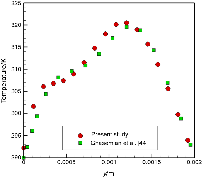
Comparison between the temperature profile at x/l = 0.5 of the current study and the results of Ghasemian et al. [44]


Results and discussion
In this section, the natural convection heat transfer of a non-Newtonian ferrofluid in a porous enclosure formed between two elliptical cylinders was addressed. The effects of four dimensionless parameters such as Rayleigh number, Darcy number, magnetic number, and the non-Newtonian power-law index were thoroughly investigated. In our simulations, the Prandtl number was set at Pr = 6, and the ratio of effective thermal conductivity and thermal conductivity of the base fluid was assumed to be \(k_{\text{eff}} /k_{\text{f}} = 8\). Moreover, the porosity of the porous medium was considered to be ɛ = 0.7, and the volume fraction of the magnetic nanoparticles was φ = 0.04.
Effect of wire positioning
In the present section, the effect of the position of the current-carrying wire as the source of a non-uniform magnetic field was examined. This study aimed at finding the most suited position for the wire, which resulted in the highest heat transfer augmentation inside the elliptical porous enclosure saturated by a non-Newtonian ferrofluid. As it is previously stated in section “Problem description,” besides the base case (i.e., case 1) in which no external magnetic field was present, three different positions for the wire were assumed including: the center of the elliptical cylinders (i.e., case 2) and the top and the bottom of the outer cylinder (i.e., case 3 and case 4, respectively).
Figure 6 depicts the variation of the average Nusselt number on the hot wall for different positions of the wire as a function of the Rayleigh number. Firstly, according to Fig. 6, regardless of the wire positioning in the range of (\(10^{4} \le {\text{Ra}} \le 10^{6}\)) the presence of an external non-uniform magnetic field increased the heat transfer rate inside the porous enclosure. Moreover, case 2 in which the wire was fixed at the center of cylinders possessed the highest Nusselt number. The maximum heat transfer enhancement occurred at (\({\text{Ra}} = 10^{5}\)), and for this case, the increase in the Nusselt number was around 150%. The lowest level of heat transfer augmentation occurred at (\({\text{Ra}} = 10^{6}\)) for case 3, which was 17%. Moreover, case 3 and case 4 showed similar thermal performances.

Effect of different positions of the wire on the averaged Nusslet number for different Rayleigh numbers (Da = 10−2, n = 0.8, Mn = 3.56 × 10⁶)
The trends mentioned above (see Fig. 6) could be explained by investigating the flow pattern and temperature contours inside the elliptical enclosure as shown in Fig. 7. For case 1, a pure buoyancy-driven flow was observed in the enclosure. In low Rayleigh number flows (Ra ≤ 105), the fluid circulation was weak inside the enclosure, and a single vortex was resolved. Moreover, the isotherms inside the cavity were smooth and elliptically shaped. Hence, the conduction heat transfer was the dominant heat transfer mechanism. By increasing the Rayleigh number, the primary recirculation zone inside the enclosure became stronger, and consequently, the thermal boundary layer on the inner cylinder notably shrank. As a result, the convective heat transfer and the average Nusselt number increased as the Ra increased. Moreover, for Ra = 106, the isotherms became highly distorted, and their horizontal symmetry was lost. Nevertheless, case 1 had the lowest heat transfer rate in comparison with other cases for which an external magnetic field was present.

Effect of different positions of the wire on the streamlines and isotherms for different Rayleigh numbers (Da = 10−2, n = 0.8, Mn = 3.56 × 10⁶)
In case 2, adding a current-carrying wire at the center of the enclosure resulted in the appearance of four new eddies, two larger eddies at the central region of the enclosure, and two smaller ones near the outer cylinder. As a result, the isotherms lost their smooth shapes in comparison with case 1. These new vortices intensified the fluid circulation inside the enclosure and increased the heat transfer rate comparing to the base case where the magnetic field was absent. The formation of these new fluid recalculation zones could be attributed to the Kelvin body force which was proportional to the gradient of the induced magnetic field. This gradient grew as the current-carrying wire was approached, and as a result, new vortices were formed in the middle of the enclosure, and due to symmetric nature of the Kelvin body force, the formed vortices are almost symmetric with respect to the semimajor axis of the enclosure. However, as Rayleigh number increased over (Ra > 105), the intensification of the natural convective flow weakened the fluid vortices located at the bottom half of the enclosure, and the flow pattern inside the enclosure lost its symmetry, as a result, the overall Nusselt number reduced on the hot cylinder as shown in Fig. 6. This trend justified the occurrence of a peak in the average Nusselt number profile when it was depicted for different Rayleigh numbers.
Similar to case 1, for case 3, also a single large eddy was present inside the enclosure, but its center was shifted toward the location of the wire at the top of the outer cylinder where the Kelvin body force peaked. This new flow pattern inside the enclosure resulted in the formation of a dead zone at the bottom of the elliptic enclosure. By increasing the Rayleigh number, the primary eddy inside the enclosure became stronger, and the superposition of the buoyancy force and the magnetic Kelvin body force shrunk the above-mentioned dead zone, and subsequently, it increased the convective heat transfer rate. As a result, the average Nusselt number monotonically increased as shown in Fig. 6 as the Rayleigh number increased for case 3. In case 4, at low Rayleigh numbers (Ra = 104–105), there were only an eddy near the bottom of the cavity and a large dead zone near the outer cylinder. The non-uniformity of the Kelvin body force stretched this primary vortex in the vertical direction and distorted the isothermal lines near the hot solid surface. But, increasing the Rayleigh number to 106 decomposed the primary eddy into two eddies. One smaller eddy, which formed due to magnetic effects in the bottom half of the enclosure and a larger one, resulted from the intensified natural fluid circulation in the top half of the enclosure. These two eddies enhanced the liquid mixing, and meanwhile, the magnetic field supports the effect of these two eddies and reduces the thermal boundary layer thickness. As a result, the Nusselt number increases by increasing the Rayleigh number for case 4 (see Fig. 6).
Effect of the strength of the magnetic field
As it is concluded in the previous section, the maximum heat transfer enhancement for a non-Newtonian ferrofluid flowing through a porous medium in the presence of an external magnetic field could be obtained in case 2. Therefore, in the present section, the effect of magnetic number (i.e., the strength of the magnetic field) on the heat transfer and fluid flow is investigated for this case. As shown in Fig. 8, as the magnetic number increased, the average Nusselt number of the hot elliptical cylinder increased subsequently for all Rayleigh numbers. As can be seen, increasing the magnetic number by one order of magnitude resulted in a more than 400% rise in the value of the average Nusselt number for all the values of the Rayleigh number studied here.

Effect of the magnetic number on the average Nusslet number on the hot wall for different Rayleigh numbers for case 2 (Da = 10−2, n = 0.8, Ra = 105)
In Fig. 9, the effect of the magnetic number is investigated on the flow and temperature fields. As can be seen, by the exertion of a more powerful magnetic field, the fluid circulation intensified in the porous enclosure. This trend notably reduced the thickness of the thermal boundary layer on the solid surfaces, which increased the heat transfer rate inside the enclosure. The shrinkage of the low-temperature region in the vicinity of the outer elliptical cylinder was the direct result of heat transfer augmentation caused by the elevation of the magnetic field intensity.

Effect of the magnetic number on the streamlines and isotherms for different Rayleigh numbers for case 2 (Da = 10−2, n = 0.8)
Moreover, at a low magnetic number of Mn = 3.56 × 10⁶, increasing the Rayleigh number slightly subdued the enhancing effect of the magnetic field. However, for higher magnetic numbers (Mn ≥ 1.43 × 10⁷), the enhancing effect of the magnetic field was almost independent of the Rayleigh number. Figure 10 shows the local Nusselt number on the hot wall for different magnetic numbers. In the upper half of the enclosure, the magnetic forces acted in accordance with the buoyancy-driven fluid flow, and as a result, the local Nusselt number significantly increased in this region as the magnetic number increased.

Effect of the magnetic number on the local Nusselt number on the hot wall in different Rayleigh numbers for case 2 (Da = 10−2, n = 0.8, Ra = 105)
However, in the lower half of the enclosure, the local Nusselt number was higher when there was no external magnetic field, because the magnetic forces and gravity acted in opposite directions. As a final note, it should be mentioned that for Mn = 0 under the pure effect of gravitational forces, the profile of the local Nusselt number was asymmetric and almost decreasing from the bottom to the top of the hot cylinder. On the contrary for Mn > 0, the effect of the magnetic forces made the Nusselt profile almost symmetric with a local maximum located at y = 0 where the effect of the magnetic field was most severe.
Effect of Darcy number
In this section, the effect of Darcy number is investigated on the flow patterns and temperature distributions inside the elliptical enclosure. As shown in Fig. 11, by increasing the Darcy number, the ferrofluid was able to flow more easily inside the porous enclosure due to a lower level of solid matrix resistance toward fluid motion. As a result, more vigorous eddies were formed in the flow domain for larger Darcy numbers. This trend intensified the fluid mixing inside the enclosure and resulted in a notably thinner thermal boundary layer on the hot elliptic cylinder. Subsequently, the heat transfer rate increased inside the porous enclosure as the Darcy number elevated. Figure 12 justifies this line of reasoning in which the variation of the average Nusselt number is drawn within the enclosure. As can be seen, a monotonic increase in the value of the average Nusselt number with Darcy number was reported. The reason was that for higher Darcy numbers the permeability of the porous medium was larger as well. As a result, the solid matrix exerted lower drag forces on the ferrofluid. This trend increased the fluid velocity magnitude in the enclosure under identical thermal conditions and raised the convective heat transfer rate inside the enclosure.

Effect of Darcy number on the streamlines and isotherms for different Rayleigh numbers for case 2 (n = 0.8, Mn = 3.56 × 10⁶)

Effect of Darcy number on the average Nusselt number on the hot wall for case 2 (n = 0.8, Mn = 3.56 × 10⁶)
Effect of the power-law index
Since the considered ferrofluid in the present study had a non-Newtonian power-law viscosity function, it was important to examine the effect of viscosity variation on the thermal performance of the ferrofluid. As shown in Fig. 13, by the increment in the power-law index, the heat transfer rate decreases. As an example, for the case presented in Fig. 13, increasing the power-law index form 0.8 to 1 and from 1 to 1.4 resulted in 29% and 41% reduction of the Nusselt number, respectively. According to streamlines and isotherms depicted in Fig. 14, for the shear-thickening fluid (n = 1.4), the eddies became weak, and consequently, the natural convection heat transfer was suppressed. As a result, the temperature distribution inside the cavity tended to the corresponding shape for the case of pure conduction inside the elliptic enclosure.

Effect of power index on the averaged Nusselt number on the hot wall for case 2 (Da = 10−2, Mn = 3.56 × 10⁶, Ra = 105)

Effect of power index on the streamlines and temperature contours in different Rayleigh numbers for case 2 (Da = 10−2, Mn = 3.56 × 10⁶)
On the contrary, for the shear-thinning liquid (n = 0.8), the fluid circulation intensified which yielded a notable heat transfer enhancement with respect to the case of a Newtonian fluid (n = 1). To justify these trends, in Fig. 15, the apparent viscosity contours are drawn for both shear-thinning and shear-thickening fluids. As can be seen, in the vicinity of the inner elliptical cylinder where the shear rate was significant, a high-viscosity zone was detectable for the shear-thickening fluid which suppressed the fluid convection and reduced the heat transfer rate. The opposite trend was reported for the shear-thinning fluid for which extremely low-viscosity levels were recognized around the inner solid surface, and the viscosity increased as the outer solid wall was approached. The maximum fluid viscosity for this case occurred at the end of the semimajor axis of the outer ellipse where the fluid circulation was the weakest.

Apparent viscosity contours for case 2 (Da = 10−2, Mn = 3.56 × 10⁶, Ra = 105)
Effect of the inner cylinder diameter
In this section of the present work, the effect of the diameter of the inner cylinder (2a) on the heat transfer and the flow pattern inside the porous material is investigated. As shown in Fig. 16, by decreasing the diameter from 2a = 1.5L to 2a = 0.5L, the average Nusselt number increased by more than a twofold. This behavior is examined in more detail in Fig. 17. For the case of 2a = 1.5L, four eddies were formed inside the enclosure: two larger eddies and two smaller ones which were located near the outer solid wall. By decreasing the diameter, the two smaller eddies became stronger; this increment in the strength of the eddies enhanced the fluid mixing and led to a considerable rise in the average Nusselt number. This effect prevailed for all the Rayleigh numbers considered in the present work.

Effect of the diameter of the inner cylinder on the averaged Nusselt number in different Rayleigh numbers for case 2 (Da = 10−2, Mn = 3.56 × 10⁶, n = 0.8)

Effect of the diameter of the inner cylinder on the streamlines and temperature contours in different Rayleigh numbers for case 2 (Da = 10−2, Mn = 3.56 × 10⁶, n = 0.8)
Effect of the outer cylinder orientation
In the last section of the present manuscript, the effect of the outer cylinder orientation on the flow patterns and heat transfer inside the porous enclosure is studied. As shown in Fig. 18, by decreasing the semimajor axis of the outer cylinder from 2d = 4L to 2d = 2L, the outer cylinder orientation changed from horizontal to vertical, and as a result, the average Nusselt number increased for all Rayleigh numbers considered here. To justify this trend, the contours of stream function and isotherms are shown in Fig. 19. As can be seen, for the vertical outer cylinder, four vortices with almost identical intensities were formed inside the enclosure, which enhanced the fluid mixing and increased the Nusslet number.

Effect of the outer cylinder orientation on the averaged Nusselt number in different Rayleigh numbers for case 2 (Da = 10−2, Mn = 3.56 × 10⁶, n = 0.8)

Effect of the outer cylinder orientation on the streamlines and temperature contours in different Rayleigh numbers for case 2
Conclusions
In the present work, the natural convection of a non-Newtonian ferrofluid inside a porous elliptical cavity in the presence of a non-uniform magnetic field was studied numerically. Numerical results were validated against pertinent numerical works in the literature. Based on the acquired results, the following conclusions were drawn:
-
The presence of an external magnetic field increased the heat transfer rate of a non-Newtonian ferrofluid inside a porous elliptical enclosure.
-
In the range of Ra = 104–106 from 17 to 150% heat transfer enhancement was achieved for different wire positions at typical values Da = 10−2, n = 0.8, and Mn = 3.56 × 10⁶.
-
The maximum heat transfer enhancement was achieved when the source of the magnetic field was located at the center of the elliptical cylinders.
-
When the wire was placed at the center of the cavity, increasing the Rayleigh number decreased the heat transfer rate, but when the wire was placed on the top or the bottom of the cavity, increasing the Rayleigh number leads to an increment in the heat transfer rate.
-
The exertion of an external magnetic field significantly altered the flow pattern and the temperature distribution inside the porous enclosure and new eddies were formed due to the magnetic Kelvin body force.
-
Increasing the intensity of the magnetic field increased the heat transfer rate. Moreover, a maximum in the local profile of the Nusselt number was reported in the vicinity of the current-carrying wire. Increasing the magnetic number by one order of magnitude resulted in a more than 400% rise in the value of the average Nusselt number for all the values of the Rayleigh number studied here.
-
Using shear-thinning ferrofluids was recommended to obtain a more significant heat transfer enhancement. Increasing the power-law index form 0.8 to 1 and from 1 to 1.4 resulted in 29% and 41% reduction of the Nusselt number, respectively.
To extend the scope of the present study, following directions could be recommended to address the heat transfer enhancement of nanofluids flowing through porous media:
-
Regarding the present study, it was shown that using an electrical current-carrying wire can increase the heat transfer rate inside an elliptical enclosure. Hence, studying the effect of multiple wires on the heat transfer rate and the temperature distribution inside the porous enclosure is highly recommended.
-
Since nanofluids in high nanoparticle volume fractions could exhibit viscoplastic behavior [52], investigating the heat transferring behavior of such fluids could be helpful.
-
Studying the ferrofluid flow and heat transfer inside 3D porous enclosures with innovative geometries is highly enticing.
Abbreviations
- a :
-
Large inner ellipse radius
- b :
-
Small inner ellipse radius
- \(\vec{B}\) :
-
Magnetic induction
- C :
-
Consistency index (Nsn m−2)
- C P :
-
Specific heat capacity (J kg−1 K−1)
- C d :
-
Inertia coefficient of porous media
- d :
-
Outer ellipse radius
- Da:
-
Darcy number
- D ij :
-
Rate of deformation tensor
- g :
-
Gravitational acceleration (ms−2)
- \(\vec{H}\) :
-
Magnetic field vector (A m−1)
- I :
-
Electrical intensity (A)
- L :
-
Reference length (m)
- m :
-
Consistency index
- Mn:
-
Magnetic non-dimensional number
- n :
-
Power-law index
- Nu:
-
Nusselt number
- P :
-
Pressure (Pa)
- Pr:
-
Prandtl number
- Ra:
-
Rayleigh number
- \(\vec{u},\,\vec{v}\) :
-
Velocity vector components (m s−1)
- x, y :
-
Cartesian coordinates (m)
- α :
-
Thermal diffusivity (m2 s−1)
- θ :
-
Non-dimensional temperature
- ν :
-
Kinematic viscosity (m2 s−1)
- μ :
-
Dynamic viscosity (kg m−1 s−1)
- μ 0 :
-
Magnetic permeability in a vacuum (= 4π × 10−7 T m A−1)
- χ :
-
Magnetic susceptibility
- β :
-
Thermal expansion coefficient (1 K−1)
- ρ :
-
Density (kg m−3)
- φ :
-
Solid volume fraction
- κ :
-
Permeability of porous medium (m2)
- τ :
-
Shear stress (Pa)
- ε :
-
Porosity
- λ :
-
Thermal conductivity (W m−1 K−1)
- avg:
-
Average
- c:
-
Cold
- eff:
-
Effective (porous media)
- f:
-
Base fluid
- h:
-
Hot
- nf:
-
Mixture (nanofluid)
- p:
-
Particle
- w:
-
Wall
References
Yu S-H, Lee K-S, Yook S-J. Natural convection around a radial heat sink. Int J Heat Mass Transf. 2010;53(13–14):2935–8.
Dondapati RS, et al. Computational prediction of pressure drop and heat transfer with cryogen based nanofluids to be used in micro-heat exchangers. Int J Mech Sci. 2017;130:133–42.
Nield DA, Bejan A. Convection in porous media, vol. 3. Berlin: Springer; 2006.
Gangawane KM, Gupta S. Mixed convection characteristics in rectangular enclosure containing heated elliptical block: effect of direction of moving wall. Int J Therm Sci. 2018;130:100–15.
Dogonchi AS, et al. Natural convection analysis in a cavity with an inclined elliptical heater subject to shape factor of nanoparticles and magnetic field. Arab J Sci Eng. 2019;44(9):7919–31.
Sheikholeslami M, et al. A study of natural convection heat transfer in a nanofluid filled enclosure with elliptic inner cylinder. Int J Numer Meth Heat Fluid Flow. 2014;24(8):1906–27.
Sheikholeslami M, Hayat T, Alsaedi A. On simulation of nanofluid radiation and natural convection in an enclosure with elliptical cylinders. Int J Heat Mass Transf. 2017;115:981–91.
Ramezanpour M, Siavashi M. Application of SiO2–water nanofluid to enhance oil recovery. J Therm Anal Calorim. 2019;135(1):565–80.
Xuan Y, Li Q. Heat transfer enhancement of nanofluids. Int J Heat Fluid Flow. 2000;21(1):58–64.
Mahian O, et al. Recent advances in modeling and simulation of nanofluid flows-Part I: fundamentals and theory. Phys Rep. 2019;790:1–48.
Mahian O, et al. Recent advances in modeling and simulation of nanofluid flows—Part II: applications. Phys Rep. 2019;791:1–59.
Roy NC. Natural convection of nanofluids in a square enclosure with different shapes of inner geometry. Phys Fluids. 2018;30(11):113605.
Abu-Nada E, Masoud Z, Hijazi A. Natural convection heat transfer enhancement in horizontal concentric annuli using nanofluids. Int Commun Heat Mass Transf. 2008;35(5):657–65.
Aminossadati SM, Ghasemi B. Enhanced natural convection in an isosceles triangular enclosure filled with a nanofluid. Comput Math Appl. 2011;61(7):1739–53.
Ho CJ, et al. Natural convection heat transfer of alumina-water nanofluid in vertical square enclosures: an experimental study. Int J Therm Sci. 2010;49(8):1345–53.
Garmroodi MD, Ahmadpour A, Talati F. MHD mixed convection of nanofluids in the presence of multiple rotating cylinders in different configurations: a two-phase numerical study. Int J Mech Sci. 2019;150:247–64.
Selimefendigil F, Öztop HF. Conjugate mixed convection of nanofluid in a cubic enclosure separated with a conductive plate and having an inner rotating cylinder. Int J Heat Mass Transf. 2019;139:1000–17.
Selimefendigil F, Öztop HF. Analysis and predictive modeling of nanofluid-jet impingement cooling of an isothermal surface under the influence of a rotating cylinder. Int J Heat Mass Transf. 2018;121:233–45.
Ghasemi K, Siavashi M. Three-dimensional analysis of magnetohydrodynamic transverse mixed convection of nanofluid inside a lid-driven enclosure using MRT-LBM. Int J Mech Sci. 2020;165:105199.
Siavashi M, et al. Numerical analysis of mixed convection of two-phase non-Newtonian nanofluid flow inside a partially porous square enclosure with a rotating cylinder. J Therm Anal Calorim. 2019;137(1):267–87.
Bozorg MV, Siavashi M. Two-phase mixed convection heat transfer and entropy generation analysis of a non-Newtonian nanofluid inside a cavity with internal rotating heater and cooler. Int J Mech Sci. 2019;151:842–57.
Siavashi M, Rostami A. Two-phase simulation of non-Newtonian nanofluid natural convection in a circular annulus partially or completely filled with porous media. Int J Mech Sci. 2017;133:689–703.
Sheikholeslami M, Ganji DD. External magnetic field effects on hydrothermal treatment of nanofluid: numerical and analytical studies. Amsterdam: William Andrew; 2016.
Selimefendigil F, Öztop HF. Numerical study and POD-based prediction of natural convection in a ferrofluids-filled triangular cavity with generalized neural networks. Numer Heat Transf Part A Appl. 2015;67(10):1136–61.
Nakatsuka K, et al. The magnetic fluid for heat transfer applications. J Magn Magn Mater. 2002;252:360–2.
Shuchi S, Sakatani K, Yamaguchi H. An application of a binary mixture of magnetic fluid for heat transport devices. J Magn Magn Mater. 2005;289:257–9.
Selimefendigil F, Chamkha AJ. Magnetohydrodynamics mixed convection in a lid-driven cavity having a corrugated bottom wall and filled with a non-Newtonian power-law fluid under the influence of an inclined magnetic field. J Therm Sci Eng Appl. 2016;8(2):021023.
Selimefendigil F, Öztop HF. Forced convection in a branching channel with partly elastic walls and inner L-shaped conductive obstacle under the influence of magnetic field. Int J Heat Mass Transf. 2019;144:118598.
Selimefendigil F, Öztop HF. MHD Pulsating forced convection of nanofluid over parallel plates with blocks in a channel. Int J Mech Sci. 2019;157–158:726–40.
Moraveji MK, Hejazian M. Natural convection in a rectangular enclosure containing an oval-shaped heat source and filled with Fe3O4/water nanofluid. Int Commun Heat Mass Transf. 2013;44:135–46.
Kefayati GHR. Natural convection of ferrofluid in a linearly heated cavity utilizing LBM. J Mol Liq. 2014;191:1–9.
Selimefendigil F, Öztop HF, Al-Salem K. Natural convection of ferrofluids in partially heated square enclosures. J Magn Magn Mater. 2014;372:122–33.
Joubert J, et al. Enhancement in heat transfer of a ferrofluid in a differentially heated square cavity through the use of permanent magnets. J Magn Magn Mater. 2017;443:149–58.
Sun X-H, et al. Natural convection and anisotropic heat transfer in a ferro-nanofluid under magnetic field. Int J Heat Mass Transf. 2019;133:581–95.
Maghsoudi P, Siavashi M. Application of nanofluid and optimization of pore size arrangement of heterogeneous porous media to enhance mixed convection inside a two-sided lid-driven cavity. J Therm Anal Calorim. 2019;135(2):947–61.
Siavashi M, Miri Joibary SM. Numerical performance analysis of a counter-flow double-pipe heat exchanger with using nanofluid and both sides partly filled with porous media. J Therm Anal Calorim. 2019;135(2):1595–610.
Siavashi M, Rasam H, Izadi A. Similarity solution of air and nanofluid impingement cooling of a cylindrical porous heat sink. J Therm Anal Calorim. 2019;135(2):1399–415.
Chamkha AJ, Selimefendigil F, Ismael MA. Mixed convection in a partially layered porous cavity with an inner rotating cylinder. Numer Heat Transf Part A Appl. 2016;69(6):659–75.
Selimefendigil F, Öztop HF. Magnetic field effects on the forced convection of CuO-water nanofluid flow in a channel with circular cylinders and thermal predictions using ANFIS. Int J Mech Sci. 2018;146–147:9–24.
Javed T, Mehmood Z, Abbas Z. Natural convection in square cavity filled with ferrofluid saturated porous medium in the presence of uniform magnetic field. Physica B. 2017;506:122–32.
Astanina MS, et al. MHD natural convection and entropy generation of ferrofluid in an open trapezoidal cavity partially filled with a porous medium. Int J Mech Sci. 2018;136:493–502.
Gibanov NS, et al. Effect of uniform inclined magnetic field on natural convection and entropy generation in an open cavity having a horizontal porous layer saturated with a ferrofluid. Numer Heat Transf Part A Appl. 2017;72(6):479–94.
Pekmen Geridonmez B, Oztop HF. Natural convection in a cavity filled with porous medium under the effect of a partial magnetic field. Int J Mech Sci. 2019;161-162:105077.
Ghasemian M, et al. Heat transfer characteristics of Fe3O4 ferrofluid flowing in a mini channel under constant and alternating magnetic fields. J Magn Magn Mater. 2015;381:158–67.
Nithiarasu P, Seetharamu K, Sundararajan T. Natural convective heat transfer in a fluid saturated variable porosity medium. Int J Heat Mass Transf. 1997;40(16):3955–67.
Khanafer K, Vafai K, Lightstone M. Buoyancy-driven heat transfer enhancement in a two-dimensional enclosure utilizing nanofluids. Int J Heat Mass Transf. 2003;46(19):3639–53.
Brinkman H. The viscosity of concentrated suspensions and solutions. J Chem Phys. 1952;20(4):571–81.
Maxwell JC. A treatise on electricity and magnetism, vol. 314. Oxford: Clarendon; 1881. p. 1873.
Scarpa F, Smith FC. Passive and MR fluid-coated auxetic PU foam—mechanical, acoustic, and electromagnetic properties. J Intell Mater Syst Struct. 2004;15(12):973–9.
Ganguly R, Sen S, Puri IK. Heat transfer augmentation using a magnetic fluid under the influence of a line dipole. J Magn Magn Mater. 2004;271(1):63–73.
Khezzar L, Siginer D, Vinogradov I. Natural convection of power law fluids in inclined cavities. Int J Therm Sci. 2012;53:8–17.
Minakov AV, Rudyak VY, Pryazhnikov MI. About rheology of nanofluids. In: AIP Conference Proceedings. AIP Publishing; 2018.
Author information
Authors and Affiliations
Corresponding author
Ethics declarations
Conflict of interest
The authors declare that they have no conflict of interest.
Additional information
Publisher's Note
Springer Nature remains neutral with regard to jurisdictional claims in published maps and institutional affiliations.
Rights and permissions
About this article

Cite this article
Daneshvar Garmroodi, M.R., Ahmadpour, A., Hajmohammadi, M.R. et al. Natural convection of a non-Newtonian ferrofluid in a porous elliptical enclosure in the presence of a non-uniform magnetic field. J Therm Anal Calorim 141, 2127–2143 (2020). https://doi.org/10.1007/s10973-019-09045-3
Received:
Accepted:
Published:
Issue Date:
DOI: https://doi.org/10.1007/s10973-019-09045-3