
Abstract
This paper shows the analysis and design optimization of wheel rim to reduce the weight and equivalent shear stress of wheel rim which is prepared by using CREO3.0 3D mechanical software, and analysis is done in ACP pre and ACP post module of ANSYS Workbench 15.0 software (Bao and Zhao in World J Eng Technol 5: 675–683 [1]). This work is done for a 14-inch regular wheel rim with updated design. In this paper, I use same material with different orientation of the composite lamina to form a multilayered wheel rim with the help of epoxy resin which is used as a binder and easily available in market at cheap price. In this paper, I am using different orientation angle of composite lamina [±25°] FW, [±35°] FW, [±45°] FW, [±55°] FW (Nirala et al. in Ref Sci J 67(4) [2]). Carbon fiber is used in supercars for wheel rim making, but carbon fibers are costlier, and in this paper, I am using a class of glass fiber which is E-glass fiber, which is less costly than carbon fiber. Wheel rim has basic requirement of good strength and aesthetic appearance, and composite material satisfies both the basic conditions of the wheel rim. After analysis, it is found that wheel having ±55° orientation has lesser stress than the currently used wheel rims.
Access provided by Autonomous University of Puebla. Download conference paper PDF
Keywords
1 Introduction
A wheel is circular made of the hard and durable material, and its center is a borehole circular in shape and connected directly with the axle of the vehicle about which wheel rotates. The wheel’s moment is used to control the vehicle. When it is connected the crank, the wheel produces or transmits energy. Earlier wheel rims are made up of steel, but it has increased the weight and reduces the performance and speed of automobiles. After more improvising on materials, nowadays, aluminum is popularly used as wheel rim material. Aluminum is lightweight material, provides aesthetic look and supports the weight by giving appropriate strength. But in order to optimize the performance and strength to weight ratio, high-end automobiles are using carbon fiber.
Carbon fiber wheel rim: It is used by high-end automobile vehicles which require performance and more durability than other conventional such as sports cars, supercars, formula one racing cars use the carbon fiber wheel rim. Since the performance of carbon fiber-based wheel rim is best and more durable than convention wheel rims, but carbon fiber is costlier that is why for public comuters conventional wheel rims are used. The basic geometrical need of supercars is that they require high strength to weight ratio, toughness, resilience and great fatigue strength that is why the composite material is used in the manufacturing of wheel rim to full body manufacturing.
E-glass is a class of carbon fiber which has high strength and no corrosive nature, cheaper than the carbon fiber.
1.1 Types of Wheel Rim
-
(a)
According to the dimensions, the wheel or rim is classified as follows:
-
1.
Drop center wheel rim (DC)
It is the mounting which is shaped in slots or groove form in such a way that there is thin gap between the bead seat parts, which placed on both sides of the rim as shown in Fig. 1.
Fig. 1 
Drop center (DC) rim
-
2.
Wide drop center wheel rim (WDC)
The design of wide drop center wheel rim is very similar with drop center wheel rim. In this, wheel’s width is expanded little bit in comparison with DC wheel rim so that its lower flange is also elongated and made deeper. Such type of design for lower rim is applied to low aspect ratio tires.
-
3.
Wide drop center wheel rim with hump
This design has a hump and placed at the starting of the bead seat area of the tire (Fig. 2).
Fig. 2 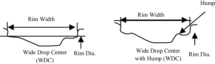
Wide drop center (WDC) and wide drop center with hump wheel rim


2 Basic Nomenclature of Wheel Rim
-
1.
Wheel: When disk and rim integrated with each other, then they form wheel.
-
2.
Rim: It is the integral part of the wheel over which the tire is seated.
-
3.
Disk: It is directly connected to wheel and mounted over the hub of vehicle axle.
-
4.
Bead Seat: It is another integral part of the rim. The purpose of bead seat is to hold the tire in radial direction when radial forces applied toward the bead face.
-
5.
Hump: The main purpose of hump is to prevent the tires for slipping from the rim when the vehicle is running and under the influence of high forces.
-
6.
Well: The well is structured in order to facilitate the easy withdrawal and tire mounting over the rim (Fig. 3).
Fig. 3 
Structure of wheel rim

3 Objective of Project
The main objectives of this study are as follows:
-
a.
To show that multilayer wheel rim is suitable for high load and forces.
-
b.
To show there is reduction in weight of wheel.
-
c.
To show the stress in E-glass fiber in different orientation.
-
d.
Wheel rim is designed as per JETMA.
-
e.
The thickness of rim area of wheel is taken as 1 mm of seven layers.
-
f.
The thickness of central part of wheel rim is taken as 1 mm of 14 Layers.
Problem Definition
To optimize the design of wheel rim, so that it will be more safe, lighter in weight with great strength than the conventional Al Alloy wheel rim used in present days. This paper has proposed the usage of E-glass fiber (Fig. 4; Table 1).

Proposed 3D designed CAD
4 Boundary Condition and Drawing
-
1.
Fixed support is provided to set of five bolt-stud holes since wheel is seated over the vehicle axle with the help of bolts through stud holes.
-
2.
The load is applied at the center of the hub in y-direction. As hub is fixed through the central hole of the rim so that maximum load is bore by this section. Total bearing load (P) = 7769.5 N.
-
3.
On the tire allocation area, there is slight pressure of 0.241 Mpa which acts normally on the circumferential tread and flange portion of the wheel.
-
4.
The diameter of tire as 550 mm, the proposed velocity of car rim taken 100 k mph, i.e., 965 rpm.
-
5.
From annexure of AIS-073 (part-2), moment is taken as 5.0969e + 5 N mm.
-
6.
Friction force is provided into the inner face of center hole which comes in action with axle (Fig. 5).
Fig. 5 
Mechanical drawing

5 Static Analysis and Simulation of Composite Wheel Rim
The following load conditions will be shown in ANSYS Workbench 15.0 in analysis chapter (Fig. 6).

Load condition for proposed wheel
Variant-1
E-glass at [−25°, +25°] FW fiber orientation.
At ±25°, maximum deformation observed in flange area of the wheel rim shown in Fig. 7 is 0.2364 mm (Fig. 8).

Total deformation of E-glass at [−25°, + 25°] FW orientation of fiber

Max stress is observed in bolt area
At ±25° orientation of the lamina, there is maximum stress of 22.884 MPa at bolt area.
Layer stack up at ±25° of lamina is shown in Fig. 9

Layer stack up at [±25°] FW
Variant-2
E-glass at [−35°, +35°] FW fiber orientation (Fig. 10).

Max stress is observed in bolt area
At ±35° orientation of the lamina, there is maximum stress of 23.739 MPa at bolt area.
At ±35°, maximum deformation observed in flange area of the wheel rim shown in Fig. 11 is 0.2192 mm.

Total deformation of E-glass at [−35°, +35°] FW orientation of fiber
Layer stack up at ±35° of lamina is shown in Fig. 12.

Layer stack up at [±35°] FW
Variant-3
E-glass at [−45°, +45°] FW fiber orientation.
At ±45°, maximum deformation observed in flange area of the wheel rim shown in Fig. 13 is 0.20061 mm (Fig. 14).

Total deformation of E-glass at [−45°, +45°] FW orientation of fiber

Max stress is observed in bolt area
At ±45° orientation of the lamina, there is maximum stress of 21.736 MPa at bolt area.
Layer stack up at ±45° of lamina is shown in Fig. 15.

Layer stack up at [±45°] FW
Variant-4
E-glass at [−55°, +55°] FW fiber orientation.
At ±55°, maximum deformation observed in flange area of the wheel rim shown in Fig. 16 is 0.19384 mm (Fig. 17).

Total deformation of E-glass at [−55°, +55°] FW orientation of fiber

Max stress is observed in bolt area
At ±55° orientation of the lamina, there is maximum stress of 18.687 MPa at bolt area.
Layer stack up at ± 45° of lamina is shown in Fig. 18.

Layer stack up at [±55°] FW
6 Conclusion
After analyzing all the four variants of composite wheel rim, we have created a table to show the stresses and deformation at different orientation angles of composite material wheel rim at a specified mentioned boundary condition.
Variants | Orientation | Total deformation | Equivalent stress (MPa) |
|---|---|---|---|
I | ±25° | 0.2364 | 22.884 |
II | ±35° | 0.2192 | 23.739 |
III | ±45° | 0.20061 | 21.736 |
IV | ±55° | 0.19384 | 18.687 |
-
In current scenario, multilayered wheel rims are used in various automobile OEM’s due to low weight and high strength along the wall thickness.
-
Determined stress is less than allowable stress, so design is safe.
-
E-glass fiber having orientation [−55, +55] FW has less equivalent stress than currently using Al alloy wheel but greater deformation, which is allowed for safer design of particular geometry.
-
It has good strength, and weight is around 7.8 kg.
-
E-glass is 25% lesser in weight, and proposed design is safer.
7 Future Scope
The paper includes the static stress analysis, optimizes the design of composite wheel rim and reduces the weight of the wheel. In order to achieve greater strength to weight ratio, an E-glass is selected with different fiber orientation. But there is further scope in dynamic analysis of wheel rim, which includes the fatigue life of wheel rim.
References
Bao, Y., Zhao, X.: Research of lightweight composite automobile wheel. World J. Eng. Technol. 5, 675–683 (2017)
Nirala, S.K., Shankar, S., Sathishkumar, D., Kavivalluvan, V., Sivakumar, P.: Carbon fiber composites: a solution for light weight dynamic components of AFVs. Ref. Sci. J. 67(4) (2017)
Schweizer, N., Giessl, A., Schwarzhaupt, O., Büter A.: Development of a composite wheel with integrated hub motor. In: ECCM15—15th European Conference on Composite Materials, Venice, Italy, 24–28 June 2012
Babu, M., Hariharan, V.S.: Modelling and analysis of automotive wheel rim. IJIRSET 5(4) (2016)
Blasco, J., Valero, F., Besa, A., Rubio, F.: Design of a dynamometric wheel rim. Springer Science + Business Media Dordrecht (2014)
Tsai S.W., Wu E.M.: A general theory of strength for anisotropic materials. J. Compos. Mater. 5, 58–80 (1971)
Gondhali, S.L., Dhale, A.D., Pagare, S.: Static structural analysis of car rim by finite element method. Springer Nature Singapore Pte Ltd. (2019)
Thakare, R.B.: Stress analysis in wheel rim by using dynamic cornering fatigue test under different conditions. IJARIIE 3(2) (2017). ISSN(O)-2395-4396
Chopade, R.B., Pateriya, A., Shirbhate, A.D.: Review of design, analysis of four wheeler alloy material rim using FEA method under cornering fatigue test. IJIIRD 2(2) (2018). ISSN: 2456-236X
Author information
Authors and Affiliations
Corresponding author
Editor information
Editors and Affiliations
Rights and permissions
Copyright information
© 2021 Springer Nature Singapore Pte Ltd.
About this paper

Cite this paper
Bisht, P.S., Awasthi, A. (2021). Analysis of E-Glass Fiber Wheel Rim by Using ANSYS. In: Muzammil, M., Chandra, A., Kankar, P.K., Kumar, H. (eds) Recent Advances in Mechanical Engineering. Lecture Notes in Mechanical Engineering. Springer, Singapore. https://doi.org/10.1007/978-981-15-8704-7_9
Download citation
DOI: https://doi.org/10.1007/978-981-15-8704-7_9
Published:
Publisher Name: Springer, Singapore
Print ISBN: 978-981-15-8703-0
Online ISBN: 978-981-15-8704-7
eBook Packages: EngineeringEngineering (R0)