
Abstract
The utilization of distorting loads has been increasing exponentially, which results power quality issues in electrical power systems. Transmission of the pollution free power is an important task for power engineers. Power quality issues may affect on end user equipment like electronic goods, digital meters etc. which results the spoilage of products. To nullify the power quality concerns the custom power devices are playing a determinant role in the power systems in the present scenario. This paper mainly demonstrates on research and topology of Shunt Active Power Filters (SAF) to magnify the quality of power in sensitive industrial loads, electrical distribution networks, transmission, and power generation systems.
Access provided by Autonomous University of Puebla. Download conference paper PDF
Keywords
- Power quality (PQ)
- Reactive power compensation
- Power factor improvement
- SAF VSC
- SAF topology
- STATCOM
- Power systems
1 Introduction
Transmission of pollution free power to the end users is one of the major key issues for the electric power engineers, because at present electrical distribution systems have almost all distorting or non-linear loads and reactive loads. Reactive power burden is more in the power system due to the reactive loads, so that the immoderate reactive power demand may increase the feeder losses and it will diminishes the active or true power flow proficiency of the distribution system. In other hands the distorting loads (non-linear loads/sensitive loads) like single phase and three phase power converters, electronic goods, electric arc furnace, digital meters etc. generates the considerable asymmetric disturbances in the ac mains, which may leads the power quality problems in the electric power systems. Today the most quite recurrent power quality issues are voltage variations, wave distortion (harmonics), transients, voltage flickering, supply frequency variations, DC off-sets, noise and notching etc. [1].
The balanced and unbalanced non-sinusoidal current generates harmonics, extravagant neutral current, reactive power, low power factor and unbalance loading of the ac mains [2]. Poor quality of power may leads to heavy power losses, power quality also degrades the consumer services, system efficiency, productivity, economic conditions and on telecommunication network’s performance. At initial stage LC passive filters were played a vital role to nullify the quality issues in the electrical power systems, but due to some determinant drawbacks of passive filters namely large in size, poor dynamic performance, enforcement of fixed compensation and resonance etc. the power engineers concentrated in their research work to develop the fast and dynamic solutions to magnify the quality of power, due to remarkable forward movement in the field of PE devices, active filters have been studied and the huge number of work have been published so that the passive filters are quickly replaced by the Active power filters. Among the different types of active filters the Shunt Active filters (SAF) have been playing a crucial role in the power quality concept. Shunt AF’s have proved to provide the efficient and effective solutions for the compensation of electric power related disturbances in electrical distribution systems. Almost all consumer’s load related power quality concerns can be solved by the shunt AF’s (STATCOM).
The organization of present article is as follows. Section 2 illustrates the power quality concerns, its consequences and standards. Section 3 describes state of art. Sections 4–7 introduces system configuration, the control strategies, advantages and applications of shunt AF’s, and conclusion respectively.
2 Power Quality Standards, Issues and Its Consequences
2.1 Power Quality Standards
In national and international level several organizations like IEEE and IEC etc. are working with the power engineers, research organizations to provide familiar platform for participated parties to work together to ensure compatibility for end-use and system equipment. According to the international standards guidelines [3] the consumption of electrical energy by the electric equipment should not produce the contents of harmonics more than the specified values. The current or voltage injections are limited based on the size of load and power systems. The standards are developed by the working group members, which describes to determine the characteristics of quality of power. According to the IEEE standards 519-1992 for below 69 kV systems, the THD value should not be equal or greater than 5 %. The frequencies of harmonic load current should not coincide with system resonances [1]. According to the IEC standards 61000-2-2* for third harmonic with multiples of 3, the compatibility level of harmonic voltage should be less than 5 %.
2.2 Power Quality Issues
One of the most prolific buzzwords in an electric power system concept is power quality. In present power scenario with the increase of usage of non-linear loads or sensitive loads drawing non-sinusoidal currents which effects on the end-use equipment [4], so that the demand for high reliable, quality of electric power has been increasing, which may leads to increase the power quality awareness by both utilities and end-users. The main power quality issues are
2.2.1 Voltage Variations
The load variations in the power system mainly results the voltage variations [5]. The real and reactive powers are directly or indirectly related to the load variations. Depending on rms voltage variations and time period these are termed as short duration and long duration voltage variations [6, 7]. The variation of voltage is mainly classified as voltage rise/swell, voltage dips/sags, voltage interruptions and long duration voltage variations. The voltage fluctuations are commonly known as voltage flicker issue which represents the dynamic variations [8] caused by varying loads in the power networks.
2.2.2 Wave Distortion/Harmonics
The technical literature was done in 1930 and 1940s on harmonics and it is defined as the integer multiple of system fundamental frequency. Harmonics comes under the wave form distortion concept. Wave form distortions (harmonics) are caused by the sensitive or distortion loads like PE devices, arc furnace and induction furnace in the power networks [1]. The distortion load is one in which the current and voltages do not have directly proportional relationship between each other. Wave form distortion is commonly classified as Notching, Noise, DC-offset, Inter harmonics.
The existence of dc content in the Ac current or voltage in the power system is known as Dc-offset. The main causes for Dc-offset are geomagnetic disturbance and Dc current in Ac network which results saturation of transformers.
2.2.3 Consequences of PQ Issues
Power quality issues like voltage variations, Transients, flickers, interharmonics and harmonics causes over loading, overheating, additional losses, saturation of transformers, data error or data loss and mall-operations of equipment like logic controller, microprocessor based controllers, power meters. Particularly on electric conductor the harmonics causes the over heat, proximity effect and skin effect.
3 State of Art
This section mainly describes the research and development activities of shunt AF’s for power quality enhancement. Since at the starting of 1970s active filters have been researched. In 1972 the shunt AF was discovered by Gyugyi, at that time the active filters could not realized to the commercial potential, because unavailability of high rated solid state power switches. The solid state technology has been developed with emergence initiation in power semiconductor field. In Japan as per [9] in the time span 1981–1996 nearly five hundreds plus shunt AF’s have been developed into commercial application due to continuous active progress. The price, size of shunt AF were reduced and other technological advancements has been improved [9], at present we have 300 kVA rated shunt active filters are available to reduce current dictation factor from 38.4 to 7.4 %. In 1973 the shunt, series active filters and the combination of these power filters have been refined and commercialized for the applications of continuous power supply. Based on voltage source converters (VSC) with capacitive energy storage and current source inverters (CSI) with inductive energy storage concept single phase active filters were developed [10], latterly 3-phase, 3-wire AF’s have been developed, as well as shunt active and series active filters are combined with passive filters for some typical configurations [11]. Many more technologies like flicker compensators, static var generators and compensators etc. have been retained in the literature. At initial stage the BJT’s, Thyristors and MOSFET’s were used for the fabrication of active filters, later GTO’s (gate-turn off thyristors), static induction thyristors (SITS’s) were employed to develop SAF [12].
With IGBT’s initiation shunt AF technology has gained a real boost, at present these are treated as ideal PE devices for the rapid growth of shunt AF’s. To provide better control actions to the AF’s several control strategies like p-q theory, Id-Iq theory and notch filter methods [13–15] etc. are developed for the development of shunt AF. To measure the performance of active filters, it is very important to develop a good computing instrument, so that these novel concepts have given an exponential growth to instrumentation technology [12]. With the presence of adequate rating of IGBT’s, advanced sensor technology, hall-effect sensors and insulation amplifiers at acceptable cost levels the shunt AF’s performance were improved. The microelectronics revolution gave the next important discovery in shunt AF’s improvement. This improvement allows to use the various control technologies like PI control, Fuzzy logic control and neutral network control etc. to improve steady state and dynamic performance of the AF’s. With this improvement shunt active filters have the ability to provide efficient and effective fast corrective action even under dynamically varying distorting loads. Shunt active filter were found to compensate very high order harmonics (up to 25th).
4 System Configurations
Even though several options are available to enlarge the quality of power, the shunt AF’s are widely implemented and accepted, because of its flexible nature and robust performance. Basically the shunt active filters are pulse width modulated VSI and CSI. Active filters are mainly classified based on phase numbers, type of converter topology (either CSI or VSI) [16], power ratings and speed of responses [17]. These classifications of shunt AF’s explained clearly with neat sketches as follows.
4.1 Converter-Based Classifications
Based on the converter type the shunt AF’s are classified as voltage-fed type and current-fed type shunt active filters. Due to its expandability [12, 16, 18], low initial cost, better efficiency voltage-fed PWM power converters are the most desired one compare to current-fed type shunt active filters. The bridge structured current-fed type PWM inverter is shown in Fig. 1. It acts as non-sinusoidal current source to reach the harmonic current requirement of distorting loads [12]. The diode is connected in series with the IGBT will block the reverse voltage (these were restricted frequency of switching). Current source inverters (CSI) have higher losses, so that it requires high rated parallel Ac power capacitor. Figure 2 shows the bridge structured voltage-fed type PWM inverter. It consist of the self-supporting Dc voltage bus with large Dc capacitor. It is more dominant, because it is cheaper, light in weight, enlargeable to multilevel and multistep versions to improve the performance with less switching frequencies [10]. The shunt AF’s with this inverter bridge mitigates the harmonics of censorious distorting loads.

Shunt AF current-fed type

Shunt AF voltage-fed type
4.2 Phase-Based Classifications
Based on the supply systems and/or load systems phase levels shunt AF’s are categorized as 1-phase (2-wire) and 3-phase (3-wire or 4-wire) systems [12].
-
(B.1)
2-Wire Active Filters: Many distorting loads, such as domestic gadgets are connected to 1-phase supply system. The two-wire AF’s are used in series, shunt and combination of both to nullify the power quality issues. Both current-fed and voltage fed PWM converters will be used to amplify the input characteristics at the supply side. Figure 3 indicates the configuration of SAF with bridge structured current source inverter using inductive storage element. The similar configuration can be obtained with voltage source bridge using capacitive storage element for shunt AF’s.
Fig. 3 
1-phase CSI type shunt AF
-
(B.2)
3-Phase, 3-wire AF’s: There are several publications which have appeared on 3-phase, 3-wire shunt AF’s. 3-Phase non-linear loads having 3-wires such as ASD’s etc. consists of the solid state power converters and laterally these type of loads are incorporated with AF’s. The configuration of 3-Phase, 3-wire shunt AF is exhibited in Fig. 4. The 3-Phase active shunt filters are also designed with three 1-phase active filters with isolation transformer for independent phase control, proper voltage matching and reliable compensation with unbalanced systems [10, 12].
Fig. 4 
Three-phase 3-wire shunt AF
-
(B.3)
3-Phase, 4-Wire AF’s: Three-phase supply system with neutral conductor may supply power to a large number of 1-phase loads, so that the systems may have reactive power burden, excessive neutral current, harmonics and unbalance. To mitigate these issues 4-wire shunt AF’s have been attempted. These 4-wire filters have been developed with voltage-fed and current-fed type converters. Figures 5, 6, and 7 indicates the configuration of 3-phase 4-wire AF’s [12]. Capacitors midpoint type AF is the first developed configuration for smaller rating applications. The complete neutral current flows through Dc capacitors having large capacitance values. In switch type shunt AF’s the fourth pole stabilize the neutral of AF. The three 1-phase bridge configuration is illustrated in Fig. 7 is a familiar version will allows the proper voltage matching to enhance the reliability of shunt AF’s [12].
Fig. 5 
3-phase 4-wire AF with midpoint capacitor
Fig. 6 
Four-wire 4-pole shunt AF
Fig. 7 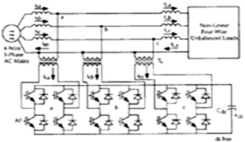
Three 1-phase 4-wire bridge type shunt AF


4.3 Power Rating-Based Classifications
The factors power rating of compensation level and response speeds are playing a principal role in deciding the feature requirement of the active filters. These two factors have reciprocal relationship. These types of filters are mainly classified based on rating and response speed [17] as follows.
Filter type | Rating | Response time |
|---|---|---|
Low power filters | <100 kVA | 100 µs–10 ms |
Medium power filters | 100 kVA–10 MVA | 100 ms–1 s |
High power filters | >10 Mva | 1–10 s |
Low power filters are again classified as 1-phase and 3-phase filters, the response time is 10 µs to 10 ms and 100 ms to 1 s for 1-phase and 3-phase power filters respectively.
4.4 Topology-Based Classifications
Classifications of active filters based on the topology used are shunt, series and universal AF’s (UPQC). The combination of series active and passive shunt filtering is known as the hybrid filters [11] which suppress low ordered harmonics at reasonable cost. Figure 2 is an example for SAF (known as STATCOM) used to mitigate harmonics and reactive power compensation, to improve PF and balancing the unbalanced currents [12].
The STATCOM mainly connected at load end to suppress the current harmonics injected by the distorting loads. Shunt AF’s can inject the equal and opposite compensating current in phase to nullify harmonics and/ or reactive component at point of common coupling (PCC). Statcom can improve the voltage profile and also stabilize the power systems. To mitigate voltage harmonics, to regulate and balance the terminal voltage of load or line series active filter is used before load (source side) with the Ac mains using matching transformer [12]. Universal active filter is a combination of series active and shunt active filters with Dc-link storage element (either Dc-bus Capacitor or Inductor), universal AF can eliminates both voltage and current harmonics at a time and has the capability to give clean power to critical loads. The main advantages of unified power quality conditioner are, it can balance and regulate the terminal voltage and mitigate the negative sequence currents [10]. The main drawback of universal AF’s are its control complexity and high cost.
5 Control Strategies
Control strategy is the heart of active filters. To generate the required compensation current, the control strategies are playing an important role in the designing of shunt AF’s. There are several control strategies like instantaneous reactive power theory (p-q theory), synchronous reference theory (Id-Iq theory), perfect harmonic cancellation method (PHC), Unity power factor method (UPF) etc. are there to extract the reference current for SAF’s connected to 3-phase source which supplies to the distorting loads. This paper the mainly demonstrates on the p-q theory and Id-Iq theory.
5.1 P-Q Theory
This Control strategy was first proposed by Akagi et al. in 1984 [19]. It is a time domain case, which can be applied for both 3-phase, 3-wire systems and 3-phase 4-wire systems. This control strategy is valid for both steady state and transient state conditions of the systems. Based on α-β transformation the set of voltages and currents are transformed from abc to α - β -0 coordinates [13, 18, 20]. Supply phase voltages are given as
Similarly reactive load currents are given by the equations
In abc coordinates a, b and c are fixed axes each displaced by 2π/3. The vectors v a , i La amplitude varies in negative and positive directions with time [13]. The α-β transformation (Clark’s transformation) is given as above equations. The real and reactive powers can obtained as
i α and i β can be obtained as
where \( \Delta = v_{\alpha }^{2} + v_{\beta }^{2} \). The powers p and q can decomposed as \( {\text{p}} = \bar{p} + \tilde{p} \), \( {\text{q}} = \bar{q} + \tilde{q} \). The reference source currents for α - β and abc transformations can be expressed [13] as
5.2 Id-Iq Theory
This theory is also known as synchronous reference frame theory (SRF). To generate the final gate or reference signal to STATCOM based on Park’s transformation the 3-phase stationary (abc) system can be transform to a rotating coordinate (dq0) system. The d-q reference frame can determined by the angle θ with respective α-β frame, which is used in instantaneous reactive power theory (p-q theory) [21, 22]. The Park’s transformation is given as
where voltage and currents are
The power equations are given [13] as follows
The d-q transformation reduces the 3-quantities to 2-quantities, because for balanced systems the zero component is omitted and when synchronous frame is aligned to voltage then μq=0. So that
Id-Iq theory is one of the most frequently used control strategy for shunt AF’s. Active and reactive power can be controlled by controlling d-q components independently.
5.3 PHC Method
This control method for active power filters is also known as “fundamental positive sequence component based method” [23]. The principal objective of this control method is to compensate the total harmonic currents and local reactive power demand. This control technique also eliminates the imbalance issues in the power system [23]. The source current will be given as
The power supplied by the source is
where k is calculated as
The reference currents are represented as follows [98].
5.4 UPF Method
Unity power factor control method for shunt connected filters is also known as “voltage synchronization method”, because of the desired in phase relationship between the gauge point voltage and source current vectors [23].
The Power delivered from source is
where the constant k is expressed as
The reference currents were calculated [98] as follows
6 Advantages and Applications of Shunt Active Filter’s
Shunt active filter is an important device to improve the quality of power in the power systems. From last decades onwards many commercial projects were developed on shunt AF’s and put into practice because of its less complexity and cost considerations. The Important advantages and applications of shunt active filters are listed as follows.
Advantages: Low cost and less complexity, small in size with high power ratings, rapid response to power disturbances improve transmission reliability and local power quality with voltage support. It has smooth voltage control over a wide range of operating conditions.
Applications/Functions: Current harmonic compensation, Load balancing for unbalanced star and delta systems, Flicker effect compensation for time varying loads, Power factor improvement, Reactive power compensation, are used to reduce the neutral current in 3-phase, 4-wire systems. Shunt active power filters play vital role in grid interconnection of green energy sources at the distribution level to improve the quality of power for both Day and Night time applications [24].
7 Conclusion
This paper represents the importance of research and development of shunt active filters with respect to non-linear loads in the power systems. Statcom is connected at load end to suppress the current harmonics injected by distorting loads; it can also improve the PF and voltage regulation. This paper gave the clear information regarding power quality issues, power quality standards, consequences, system configurations, control strategies, and an important advantages and applications of shunt active filters (Statcom). Over last two decades onwards due to continuous active research progress achievement in static reactive compensation (SAF) technology has produced remarkable or significant benefits to end-users, utility and wind form developers.
References
Rogar C Dugan “Electrical Power Systems Quality, Surya Santosa” markF.mc Granaghana, Surya Santoso. IEEE, transactions.
J. Nastran, R. Cajhen, M. Seliger, and P. Jereb, “Active Power Filters for Nonlinear AC loads, IEEE Trans. on Power Electronics Volume 9, No. 1, pp. 92–96, Jan(2004).
M. F. McGranaghan, “Overview of the Guide for Applying Harmonic Limits on Power Systems—IEEE P519A,” Eighth International Conference on Harmonics and Quality of Power, ICHQP Athens, Greece, pp. 462–469, (1998).
K. Eichert, T. Mangold, M. Weinhold, “PowerQuality Issues and their Solution”, in VII Seminario de Electrónica de Potencia, Valparaíso, Chile, Abril (1999).
T.J.E. Miller “Reactive power control in electric systems”, IEEE Transactions, ISBN: 978-81-265-2520-1.
G.Yalienkaya, M.H.J Bollen, P.A. Crossley, “Characterization of Voltage Sags in Industrial Distribution System”, IEEE transactions on industry applications, volume 34, No. 4, July/August, pp. 682–688, (1999).
Haque, M.H., “Compensation Of Distribution Systems Voltage sags by DVR and D-STATCOM”, Power Tech Proceedings, 2001 IEEE Porto, Volume 1, pp. 10–13, September (2001).
Bollen, M.H.J., “Voltage sags in Three Phase Systems”, Power Engineering Review, IEEE, Volume 21, Issue: 9, pp. 11–15, September (2001).
H. Akagi. New trends in active filters for power conditioning. IEEE Transactions on Industrial Applications, 32(6):1312–1322, November/December (1996).
Sandeep G J S M, Sk Rasoolahemmed EEE KL. UNIVERSITY, Asst. Professor, EEE KL. university 2013 Importance of Active Filters for Improvement of Power Quality. International Journal of Engineering Trends and Technology (IJETT)—Volume 4 Issue 4-April. (2013).
Z. Chen, F. Blaabjerg, and J.K. Pedersen. A study of parallel operations of active and passive filters IEEE Power Electronics Specialists Conference, 33rd Annual (2):1021–1026, June (2002).
B. Singh, K. Al-Haddad, and A. Chandra. A review of active filters for power quality improvement. IEEE Transactions on Industrial Electronics, 46(5):961–971, October (1999).
Milands. M. I, Cadavai. E. R, and Gonzalez. F. B, “Comparison of control strategies for shunt active power filters in three phase four wire system,” IEEE Trans. Power Electron., vol. 22, no. 1, pp. 229–236, Jan. (2007).
Charles. S, Member, IACSIT, G. Bhuvaneswari, Senior Member, IEEE “Comparison of Three Phase Shunt Active Power Filter Algorithms”. International Journal of Computer and Electrical Engineering, vol. 2, no. 1, February, (2010).
S. Buso, L. Malesani, and P. Mattavelli, “Comparison of current control techniques for active filters applications,” IEEE Trans. Ind. Electron., vol. 45, no. 5, pp. 722–729, Oct. (1998).
J. Nastran, R. Cajhen, M. Seliger, and P. Jereb, “Active Power Filters for Nonlinear AC loads, IEEE Trans. on Power Electronics Volume 9, No. 1, pp. 92–96, Jan (2004).
M.K. Darwish and P. Mehta. Active power filters: A review M. El-Habrouk, IEE Proc.-Elertr. Power Appl., vol. 147, no. 5, September (2000).
R. S. Herrera, P. Salmeron, and H. Kim, “Instantaneous reactive power theory applied to active power filter compensation: Different approaches, assessment, and experimental results,” IEEE Trans. Ind. Electron., vol. 55, no. 1, pp. 184–196, Jan. (2008).
H. Akagi, Y. Kanazawa, and A. Nabae. “Generalized theory of the instantaneous reactive power in threephase circuits.” IPEC’83—International Power Electronics Conference, Toyko, Japan, 46(5):1375–1386, (1983).
J. Afonso, C. Couto, and J. Martins, “Active filters with control based on the p–q theory,” IEEE Ind. Electron. Soc. Newslett., pp. 5–11, Sep.
M. Aredes, J. Hafner, and K. Heumann, “Three-phase four-wire shunt active filter control strategies,” IEEE Trans. Power Electronics, vol. 12, no. 2, pp. 311–318, (1997).
S. Bhattacharya & D. Divan, “Synchronous frame based controller implementation for a hybrid series active filter system,” in Proc. 13th IAS Annual meeting, pp. 2531–2540, (1995).
María Isabel Milanés Montero, Member, IEEE, Enrique Romero Cadaval, Member, IEEE, and Fermín Barrero González, Member, IEEE “Comparison of Control Strategies for Shunt Active Power Filters in Three-Phase Four-Wire Systems”, IEEE Transactions on Power Electronics, vol. 22, no. 1, January (2007).
Rajiv K. Varma, Senior Member, IEEE, Shah Arifur Rahman, Member, IEEE, and Tim Vanderheide, Member, IEEE “New Control of PV Solar Farm as STATCOM (PV-STATCOM) for Increasing Grid Power Transmission Limits During Night and Day”, IEEE Transactions on Power Delivery, vol. 30, no. 2, April (2015).
Author information
Authors and Affiliations
Corresponding author
Editor information
Editors and Affiliations
Rights and permissions
Copyright information
© 2016 Springer India
About this paper
Cite this paper
Popavath, L.N., Palanisamy, K., Kothari, D.P. (2016). Research and Topology of Shunt Active Filters for Quality of Power. In: Satapathy, S., Mandal, J., Udgata, S., Bhateja, V. (eds) Information Systems Design and Intelligent Applications. Advances in Intelligent Systems and Computing, vol 433. Springer, New Delhi. https://doi.org/10.1007/978-81-322-2755-7_18
Download citation
DOI: https://doi.org/10.1007/978-81-322-2755-7_18
Published:
Publisher Name: Springer, New Delhi
Print ISBN: 978-81-322-2753-3
Online ISBN: 978-81-322-2755-7
eBook Packages: EngineeringEngineering (R0)