
Abstract
The shoulder girdle is frequently involved in acute trauma and overuse in sports. Imaging has an important role in diagnosis and follow-up of articular and extra-articular shoulder lesions. The volume of this chapter is too short to provide in-depth discussion; it has the intention to give a basic and concise overview of the techniques, indications, and diagnosis with focus on staging and novel developments.
Radiographic evaluation remains the cornerstone of primary imaging of the shoulder. Conventional magnetic resonance imaging (C-MRI), MR arthrography (MRA), and ultrasound (US) are increasingly being used to assess presence rotator cuff tears and their extent, and to assist in planning surgical treatment. MRA (direct and indirect) is the most accurate and sensitive available imaging method for the detection of labral tears (glenoid labrum, Bankart and SLAP lesions). Indirect MRA (I-MRA) is more and more regarded as a standard practice in patients with shoulder instability due to suspected labral pathology where further investigative imaging is indicated. CT arthrography (CTA) may be used as an alternative for direct MRA in cases of contraindication for MRI.
Access provided by Autonomous University of Puebla. Download chapter PDF
Keywords
These keywords were added by machine and not by the authors. This process is experimental and the keywords may be updated as the learning algorithm improves.
1 Imaging of the Shoulder Girdle
The shoulder girdle is frequently involved in acute trauma and overuse in sports. Imaging has an important role in diagnosis and follow-up of articular and extra-articular shoulder lesions. The volume of this chapter is too short to provide in-depth discussion; it has the intention to give a basic and concise overview of the techniques, indications, and diagnosis with focus on novel findings.
Radiographic evaluation remains the cornerstone of primary imaging of the shoulder girdle in case of acute trauma (glenohumeral and AC dislocation, fractures, strain) and chronic overuse with impingement.
Conventional magnetic resonance imaging (C-MRI), MR arthrography (MRA), and ultrasound (US) are increasingly being used to assess the presence and size of rotator cuff tears to assist in planning surgical treatment (Lenza et al. 2013). C-MRI, MRA, and US have good diagnostic accuracy, and any of these tests could equally be used for detection of full-thickness tears in people with shoulder pain for whom surgery is being considered. MRA (direct and indirect) is the most accurate and sensitive available imaging method for the detection of labral tears (glenoid labrum, Bankart and SLAP lesions). Indirect MRA (I-MRA) is more and more regarded as a standard practice in patients with shoulder instability due to suspected labral pathology where further investigative imaging is indicated (Fallahi et al. 2013). CT arthrography (CTA) may be used as an alternative for direct MRA (D-MRA) in cases of contraindication for MRI.
1.1 Radiography and CT
Radiographic examination remains the mainstay and primary imaging examination of the shoulder girdle in case of trauma, glenohumeral and acromioclavicular joint complaints, subacromial impingement, and mass lesions. Radiographic examination of the shoulder includes multiple views to investigate the glenohumeral and acromioclavicular (AC) joint, manubrioclavicular joint, scapula, clavicula, and humerus (Table 17.1) (White et al. 2008). Radiographs are tailored on the clinical findings and questions. Specific trauma series of the glenohumeral joint, AC joint, clavicula, and scapula are performed to document dislocations and fractures (Table 17.1) (Smekal et al. 2008; Schnabel et al. 2004; Philipp et al. 2004). Also specific series with images in prone and standing positions are made in case of glenohumeral joint disease (degenerative or inflammatory) and subacromial impingement complaints (Fig. 17.1a–c) (Table 17.1). Subacromial impingement series include axial images of the scapula (scapular Y view) to describe acromion types according to Bigliani and Gagey (Natsis et al. 2007). Generally radiographic examination is reduced to 2 or 3 views; specific views are avoided and substituted by non-enhanced reduced radiation dose volume CT with two-dimensional and three-dimensional multiplanar reconstructions (Kuhlman et al. 1988). Radiographs are indicated for postoperative evaluation and follow-up of osteosynthesis and prosthesis.

(a–c) Radiograph of the glenohumeral joint, subacromial impingement series, including AP view (a) in prone position for evaluation of the subacromial space and AC joint, standing ¾ view of the glenohumeral joint (b) and standing scapular Y view for evaluation of subacromial spur (arrow) and acromion shape type 2 (curved) according to Bigliani
1.2 Ultrasound
Ultrasound is a cost-effective and accurate examination for the evaluation of the RC, SA-SD bursa, the AC joint, extra-articular and rotator interval (RI) part of the CL biceps, and other shoulder girdle muscles except for the SSC. Rutten compared the performance of US, 1.5 T C-MRI, and 1.5 T D-MRA (Rutten et al. 2010). He concluded that following US of the shoulder performed by a dedicated radiologist, MRI offers little additional value, with regard to the detection of rotator cuff tears. Personal expertise plays a crucial role in choosing which imaging technique will be used (Rutten et al. 2010) (Table 17.1). As a result of the low therapeutic consequence of non-detection of low-grade partial-thickness RC tears, US is regarded as the primary investigation tool. Advantage of US over MRI is the dynamic evaluation of impingement during elevation or endorotation. The long head tendon of the biceps (LHB) in its extra-articular course and the peripheral part of the biceps pulley and interval area is accurately demonstrated. Acromioclavicular joint capsule integrity and dislocation is evaluated in rest and dynamically during cross arm test or by compression of the lateral half of the clavicula. The glenohumeral joint is not documented on US examinations except for the joint cavity on posterior cranial approach.
1.3 MRI Examination Procedure
MRI is the only technique that covers all anatomic areas, including bony and soft tissue structures of the shoulder girdle.
MRA is the best technique to study the glenohumeral joint. In direct MRA (D-MRA) the shoulder joint can be approached from anterior and posterior. The posterior approach has the advantage that contrast extravasation in the anterior structures and erroneous interpretation are avoided. A small amount of iodinated contrast radioscopically to prove intraarticular needle position is followed by 10 ml Gd 1/200 solution; ready-to-use diluted Gd-DOTA solutions are commercially available (Artirem®).
I-MRA is an MR technique improving articular and periarticular contrast compared to D-MRI. It is achieved by injection of paramagnetic MR contrast media intravenously (IV). After the IV injection, exercising the joint for an average of 15 min. results in considerable signal intensity increase within the joint cavity and in pathologic tissue. The method is less invasive than D-MRA.
FS MR sequences yield arthrographic images (Figs. 17.2a–c, e and 17.3a–d). Three to the glenoid orthogonal imaging planes are used in neutral arm position (Fig. 17.3a–d and Table 17.2). ABER position (abduction and external rotation) is described by Tirman to improve detection of lesions of the anterior-inferior labral pathology, articular sided tears of the infraspinatus, and posterior impingement lesions (Fig. 17.11) (Tirman et al. 1994a, b; Cvitanic et al. 1997). Other positions may be used as there are ADIR (adduction and internal rotation) or FADIR (flexion adduction and internal rotation). FADIR positioning appears to be a useful adjunct in evaluating patients with equivocal or subtle posteroinferior labral abnormalities on conventional MRA sequences (Chiavaras et al. 2010).

(a–f) Three imaging planes orthogonal to the glenoid articular surface. (a) Mid-glenoid coronal image with demonstration of axial imaging plane and imaging volume perpendicular to the glenoid articular surface. (b) Axial imaging plane at the dotted line in (a). (c) Mid-glenoid axial image with demonstration of sagittal imaging plane and imaging volume parallel with the glenoid articular surface. Arrow: middle glenohumeral ligament. Short arrow: superior glenohumeral ligament. Arrowhead: anterior labrum. (d) Sagittal imaging plane at the dotted line in (c). (e) Mid-glenoid axial image with demonstration of coronal imaging plane and imaging volume parallel with the glenoid articular surface. (f) Coronal imaging plane at the dotted line in (c)

(a–d) Comparison of 1.5 T I-MRA and 1.5 T D-MRA on T1-WI with FS in a normal shoulder joint. (a–c) I-MRA in coronal (a, b) and axial (c): gadolinium enhancement at the AC joint, glenohumeral joint with tendon sheath of CL, and SA-SD bursa. (d) D-MRA in coronal imaging plane: gadolinium enhancement at the glenohumeral joint only, axillary joint capsule insertion on humerus (b short arrow), axillary pouch of joint recess filled with gadolinium (b long arrow)
It is expected that with use of 3 T MRI or higher magnetic fields the increased contrast and spatial resolution on T2 or intermediate TE WI FS will lead to better evaluation even without gadolinium administration (Fig. 17.21a, b).
1.4 CT Arthrography
CTA generally is substituted by MRA (D-MRA or I-MRA). For cartilage lesions and intraarticular lesions of the biceps, an improved detection of lesions is reported. Omoumi et al. compared CTA and D-MRA with arthroscopy prospectively for hyaline cartilage lesions (Fig. 17.4a, b). They found only moderate diagnostic performance for both techniques, although better for CTA (sens 46.4–82.4 %; spec 89.0–95.9 %) compared to D-MRA (sens 31.9–66.2 %; spec 91.1–97.5 %) (Omoumi et al. 2014).

(a, b) Glenoid version. Glenoid version is calculated on axial reconstructed multiplanar images perpendicular to the glenoid articular surface in the coronal and axial imaging plane; this is the true glenoid axial plane (a). The image inferior to the base of the coracoid process is selected (b). Tangent line to the lateral margin of the labrum is drawn, and the axis of the scapula is defined and drawn (b). A line perpendicular to the glenoid tangent is drawn (b dotted line). In retroversion negative version angles are calculated. In calculation of glenoid version. Anterior glenoid capsule insertion (b arrow)
2 Normal Anatomy and Variants
Normal anatomical variants have to be recognized and discriminated from relevant pathology. Variant anatomy may have a role in symptomatic shoulder complaints (Zhang et al. 2014).
2.1 Cartilage and Glenoid Variants
Humeral head cartilage is thicker centrally; a bare area, not covered with cartilage, is located posterior cranial at the humeral head at the junction of joint capsule and articular cartilage (Fig. 17.5a). This bare area should be discriminated from Hill-Sachs impact. Hill-Sachs lesion starts more superiorly above the level of the coracoid process on axial images. An additional bare area has been described between the supraspinatus insertion on the greater tuberosity and the adjacent articular cartilage. Failure to recognize and account for these bare areas at imaging may lead to erroneous diagnosis or overestimation of SSP partial-thickness tears (PTT).

(a, b) A 3 T I-MRA of left shoulder in patient with complaints of subcoracoidal impingement. (a) Axial T1-WI FS. (b) Sagittal T2-WI. Major expansion of the synovial space related to increased amount of synovial fluid demonstrated on (a). Bare area posterior (a double headed arrow) medial to capsular insertion not covered with hyaline cartilage. Complete SSC tendon tear (a, b arrow) with retraction medial tot the coracobrachial tendon (a short arrow)
The glenoid articular surface is located in 7° retroversion if calculated in the true glenoid axial plane (Rouleau et al. 2010). Glenoid retroversion should be calculated orthogonal to the glenoid articular surface; this is called the true glenoid axial plane. This true glenoid axial plane includes reconstructed multiplanar images with inclination in the axial and coronal imaging plane (Fig. 17.4a). If a strict axial imaging plane is chosen, retroversion is overestimated. Optimally the lateral labral margin has to be included in the glenoid tangent (this implies MRI or CTA) (Fig. 17.4a, b). Decreased retroversion leads to increased risk of anterior dislocation. The most frequent cause of reduced retroversion is Bankart lesion with or without bony fragment.
The cartilage of the glenoid is thinner centrally. The tubercle of Assaki is a central thickening of subchondral bone at the level of this cartilage thinning (De Wilde et al. 2004). Infrequently a bare spot of focal well-demarcated articular cartilage defect at the central aspect of the glenoid is present (Fig. 17.6a, b); this condition is less frequent in children.

(a, b) Normal variant, bare area humeral head, 3 T I-MRA, TSE T1-WI with FS. (a) Axial and (b) coronal mid-glenoidal imaging planes with centrally located defect at the hyaline cartilage (margins of the defect are marked with long arrows), labrum (short arrow a), labrocartilaginous junction (arrowhead b)
The glenoid can be shallow or hypoplastic predisposing to instability.
2.2 Labral Variants
The glenoid labrum is a ring of fibrocartilaginous tissue that surrounds the glenoid rim (Fig. 17.2d). The labrum increases the depth of the glenoid cavity, functions as a pressure seal (negative pressure) during motion, and provides stability and shock absorption to the shoulder joint. Transverse sections of the labrum reveal commonly a triangular shape (anterior 64 %; posterior 47 %) (Figs. 17.2b and 17.6a short arrows); it may be rounded (anterior 17 %; posterior 33 %) (Fig. 17.2b arrowhead) or rarely flat, cleaved, notched, or even absent (Figs. 17.7 and 17.8 arrows). The size has a broad variation from 2 to 14 mm leaving size criteria of little diagnostic use. Also the SI of the labrum is variable (Loredo et al. 1995). Initially the labrum was considered to be of low SI on all MR pulse sequences. More recent studies have identified areas of increased linear or globular signal intensity in nearly a third of arthroscopically normal labrum tissue (Table 17.3). Posterosuperior labrum increased signal is possibly related to magic angle phenomenon (B0 of 55° on 1.5 T).

Anterior labral variants: sublabral foramen documented on 3 T I-MRA. I-MRA with series of axial images superior to the glenoid up to the middle third of the glenoid. Sublabral foramen (arrow) is detected at the anterior half of the glenoid

Anterior labral variants: sublabral foramen documented on CTA. CTA with axial images, sublabral foramen (arrow)
The superior portion of the labrum can be mobile and lax, a variant that is recognizable with arthroscopy.
The superior and anterosuperior regions of the labrum have the poorest blood supply, which slows the healing process of SLAP tears in this location.
The labrocartilaginous transition may present as an abrupt transition with the labrum demonstrating a free edge margin (type A attachment) (Fig. 17.2b, arrow) or the transition zone may blend with the hyaline cartilage (type B attachment) (Fig. 17.6a arrowhead) (Dunham et al. 2012).
2.2.1 Superior Labrum Variants
Fifty percent of the biceps tendon fibers arise from the superior glenoid labrum and the remainder from the supraglenoid tubercle. Three distinct types of biceps-labral complex (BLC) are recognized (Table 17.4) (Figs. 17.6b arrow and 17.2a arrow). A bicipital labral sulcus is a cleft between the labrum and the biceps.
2.2.2 Anterosuperior Labrum Variants
Sublabral recess, sublabral foramen, and Buford complex are frequent variants of the anterior labrum (Kreitner et al. 1998).
-
Sublabral recess (type II and III BLC) represents the most frequent normal anatomic variant of the anterior superior labrum. A recess deeper than 2 mm is present in 39 % of specimens. It follows the contour of glenoid cartilage and is smooth, with 1–2 mm width, and has no extension to superior labrum. A perilabral cyst is not present. The recess can extend posterior from the biceps tendon. Three classic key features differentiate recess from a SLAP tear (Table 17.5).
Table 17.5 Three classic key features to differentiate a sublabral recess from a SLAP tear -
A sublabral foramen is detected in 10–15 % of arthroscopies and located between 1 and 3 o’clock. An associated osseous indentation is possible (Figs. 17.7 and 17.8). It should not extend below the level of the mid-glenoid notch. It can be attached to the anterior-inferior labrum through a “labral slip”: a communication between the glenohumeral joint and the subscapularis recess is found. Seventy-five percent are associated with cordlike MGHL (Buford), and a sublabral foramen may coexist with a sublabral recess. A foramen is differentiated from a labral tear or loosening based on the smooth margins of the foramen, the lack of associated traumatic injuries in the adjacent capsuloligamentous structures, and absence of significant displacement (<1–2 mm) of the detached labrum. Joint fluid that accesses to the subscapularis recess through the sublabral foramen should not be misinterpreted as a type II SLAP tear with associated paralabral cyst.
-
In Buford complex, which is found in 6 % of shoulder arthroscopies, the anterosuperior labrum is absent with thickening of middle glenohumeral ligament (MGHL) (Figs. 17.9a, b and 17.10a, b). If the cordlike structure is followed on consecutive axial images, the superior origin and distal capsular merge is demonstrated. An increased association of Buford complex and sublabral foramen with SLAP lesions is reported in literature. The presence of anterosuperior labral variant anatomy may result in higher stress on the superior BLC, predisposing to injury.

(a, b) Anterior labral variants: Buford complex demonstrated on 3 T I-MRA. I-MRA with axial T1 FS images in middle third (a) and at the cranial third of the glenoid (b) demonstrating absent anterior labrum A and thick middle glenohumeral ligament (Buford complex) (arrow a, b)

(a, b) Anterior labral variants: Buford complex demonstrated on CTA. Axial mid-glenoidal image of left normal shoulder (a) demonstrating normal anterior labrum (a arrow) and axial mid-glenoidal image of right shoulder (b) demonstrating thick middle glenohumeral ligament (b arrow) an (d) absent labrum in Buford complex
2.3 Glenohumeral Ligaments and Variants
-
The SGHL is nearly invariably present, in 97 % at arthroscopy. Variants include a common origin with the MGHL and/or direct origin from the biceps tendon. A rare variant is a SGHL origin from the posterior labrum with a course overriding the biceps tendon origin without attaching to the anterior labrum or MGHL. Normally the SGHL is rather thin but may be thickened in patients with an underdeveloped or absent MGHL. Distally the SGHL merges with the coracohumeral ligament (CHL) to form the CL biceps pulley (Fig. 17.2d small arrow). Distally the CL biceps pulley fuses with the anterior part of the SS and inserts on the greater and minor humeral tubercle and thus acts as a stabilizer of the CL biceps at the entrance of the intertubercular sulcus.
-
The MGHL has a variable origin, merges with the anterior capsule along SSC, and inserts on the lesser tubercle (Fig. 17.2d long arrow and c short arrows). The structure is well demonstrated if followed on continuous axial slices. It is redundant in internal rotation and stretched in external rotation and limits anterior translation in 60–90° shoulder abduction. The MGHL has a variable origin, either on labrum (Fig. 17.2c medial short arrow) or medial to the labrum (Fig. 17.4b arrow); it may have a common origin with the SGHL and biceps tendon or have a conjoined origin with the biceps tendon alone or on the IGHL. The MGHL is absent in 1/3th of the shoulders; this finding is associated with prominent subscapular recess. It may be cordlike in Buford complex with absent AS labrum (Figs. 17.9a, b and 17.1a, b). Longitudinal splitting or duplication of the MGHL has been reported as a normal variant or a partially healed longitudinal split tear of the MGHL. The foramen of Weitbrecht is located between the SGHL and MGHL (Fig. 17.8 black arrow). If the MGHL is absent, a single large communication with a redundant subscapular recess is present. A thickened and high riding MGHL may lead to narrow the foramen. A sublabral foramen may present as a pseudoparalabral cyst. The foramen of Rouvière is located between the MGHL and IGHL.
-
The IGHL is composed of an anterior band (“U shape”), and between those posterior band the axillary recess. It represents a fibrous thickening of the shoulder capsule and is the most consistently present and the most important stabilizator of GH joint. The anterior band runs from the mid-glenoid notch, between 2 o’clock and 4 o’clock, and is thicker than the posterior band. In ABER position (Fig. 17.11a–c arrows), the anterior band of the IGHL becomes taut and is well visualized along its entire course. A high origin anterior band should not be mistaken for an anterior labral tear on MRA. The posterior band has its origin between 7 o’clock and 9 o’clock. Two distinct patterns of humeral insertion are recognized: (1) collar-like attachment in which the entire IGHL inserts slightly inferior to the articular edge of the humeral head (Fig. 17.3b arrow) and (2) a V-shaped attachment in which the anterior and posterior bands of the IGHL attach adjacent to the articular edge of the humeral head. The axillary pouch attaches at the apex of the V distal to the articular edge.
Fig. 17.11 
(a–c) MRI in ABER position. (a) Prone position with shoulder in abduction and external rotation; imaging plane C is drawn. (b) Localizer image in to the glenoid coronal plane. This plane is used to plan the to the glenoid sagittal imaging plane C. (b) 1,4,7,10 slice positions in glenoid coronal plane
Variant origin of the anterior band of the IGHL from the MGHL is described; also a high origin anterior band is described and could be mistaken for an anterior labral tear on MRA. The insertion of the inferior glenohumeral ligamentous complex on the surgical neck of the humerus frequently results in a jagged appearance on axial images. The posterior band may be thicker than the anterior band. A band of connective tissue also called “the periarticular fiber system” attaches the IGHL to the SGHL (Huber and Putz 1997).
-
A spiral GHL arises from the axillary component of the IGHL and the infraglenoid tubercle and courses laterally to fuse with the MGHL and may be demonstrated on axial and oblique sagittal MRA planes (Merila et al. 2004).

2.4 Capsular Insertions
Three types of anterior capsule insertion are recognized. Type I with insertion at the glenoid margin (Fig. 17.2c medial arrow), type II inserts at the glenoid neck (Fig. 17.8 arrowhead), and type III inserts more medially along the scapula (may predispose to instability) (Fig. 17.4b arrow). Do not misinterpret over-distension of the joint capsule as a type III capsular insertion. The posterior capsule should always insert on the glenoid rim (Fig. 17.8 thick arrow)!
2.5 Biceps Pulleys and Rotator Interval
The biceps pulleys are the coracohumeral ligament (CHL), SGHL, and transverse ligament (TL) (Fig. 17.12a–c).
RI is the triangular space at the anteriosuperior aspect of the glenohumeral joint between the SSP and SSC tendons, the coracoid process as its base, the superior aspect of the intertubercular groove as its apex. The CHL is sometimes described as a capsular fold rather than a true ligament located at the superficial (bursal) aspect of the glenohumeral joint capsule in the RI. The lateral band (largest) inserts on the greater tubercle and merges with the SSP; the medial band (smallest) merges with the SGHL and inserts on the lesser tubercle and SSC. The SGHL runs over the scapular neck, and glenoid parallels intraarticular the course of the LHB tendon. Together with CHL it forms a U-shaped anterior sling extending along the LHB tendon that limits medial subluxation of the intraarticular LHB tendon over the edge of the lesser tuberosity (Fig. 17.12a–c) (Ho 1999; Weishaupt et al. 1999; Schaeffeler et al. 2012; Nakata et al. 2011; Tagliafico et al. 2014; Zanetti and Pfirrmann 2004).

(a–c) Schematic drawings of transverse cuts of the biceps pulley. (a) Near the origin of the ligaments at the base of the coracoid process. (b) Middle third of rotator interval (RI). (c) Lateral at the entrance of the LHB in the intertubercular groove (thin arrow), the LHB is covered by the transverse ligament (TL) that is anatomically an extension of the SSC tendon. Medially (a) the SGHL and GHL are distinct structures with separate origin at the base of the coracoid process. Centrally (b) the superior glenohumeral ligament and coracohumeral ligament fuse anteromedially to form a pulley that most laterally (c) fuses anteriorly with the minor tubercle and SSC and laterosuperior to the SSC and greater tubercle of the humerus. In this area the pulley is covered by the TL
2.6 Long Head of the Biceps
The presence of one or more supernumerary heads of the LHB tendon is described. The prevalence of a three-headed biceps brachii is estimated to be 10–20 %. The origin is located at the supraglenoid tubercle and superior labrum, the second slip adjacent to the LHB tendon origin and at the glenohumeral joint capsule, and the third slip at the margin of the greater or lesser tuberosity at the proximal aspect intertubercular groove (Vinson et al. 2012). Two separate tendons are visible in the intertubercular groove (Fig. 17.13a, b). The accessory tendon is often flat in appearance (Fig. 17.13a arrow), the adjacent LHB tendon more rounded. It is difficult or impossible to distinguish between an accessory tendon and a longitudinal tear. Features that favor an accessory tendon are the flattened appearance and most important the separate site of origin for the accessory tendon.

Split long head of the biceps tendon, 3 T I-MRA. Axial T1-WI FS (a) and coronal T1-WI FS (b) showing two LHB tendons (arrows) at intertubercular groove (a, b) and superior to the groove (b)
A complete absence of the intraarticular portion of the tendon is very rare.
Variants at the anchor and proximal IA LHB variants are also known. In the absence of the normal glenoid origin, the tendon is adherent to or incorporated within the superior joint capsule. A “bifurcate” or “Y-shaped origin” of the LHB tendon is described with two separate origins that merge together before exiting the joint as a single tendon (one from glenoid, one from rotator cable or superior capsule) (Wittstein et al. 2012). Prevalence is about 2 %.
Aberrant intraarticular origin of the LHBT from the anterior edge of the supraspinatus tendon may contribute to symptomatic concomitant rotator cuff pathology; these patients are treated with tenodesis of the LHBT to relieve symptoms (Zhang et al. 2014). Possible lack of extension of intraarticular contrast material into the intertubercular groove is mostly misinterpreted as biceps tear. The clue to the diagnosis is the absence of such features as a tendon stump, tendon degeneration, and retracted distal tendon.
3 Pathology
3.1 Clavicle, AC, and Sternoclavicular Joint
Clavicle fracture and AC instability are frequent findings in contact sports and fall of bikers. Acute sternoclavicular joint subluxation/dislocation is a rare finding.
Radiography is useful for the initial assessment of suspected disorders of the clavicle, sternoclavicular, and acromioclavicular joints.
Radiographically two AP views for the clavicle and AP and scapular Y views for the AC joint are made (Table 17.1).
US has been described as a screening tool to assess possible sternoclavicular joint dislocation; however, it is usually used only if CT and MRI are not readily available.
AC joint instability is graded by Tossy-Rockwood in six types (Table 17.6). US to grade AC joint instability is as reliable as radiographic measurement (Kock et al. 1994; Heers and Hedtmann 2005, Tossy et al. 1963; Rockwood et al. 1996). Disrupted deltoid and trapezius insertion and common fascia were demonstrated on US in all patients classified according to Rockwood’s classification as type V, half of the patients classified as type IV, about a quarter of patients classified as type III, and only in a minority type II injuries (Table 17.6).
Although US is increasingly used as a primary investigation tool to demonstrate AC dislocation in a dynamic way (during cross arm test or with compression of the clavicle), it has a limited role in the evaluation of the AC joint itself, where it is most useful to exclude the presence of joint inflammation with increased joint fluid and Doppler signal (Heers and Hedtmann 2005; Matter et al. 1995). If joint fluid is detected on US, it is considered a nonspecific finding, which could represent active inflammation or simply joint effusion due to degenerative osteoarthritis.
CT allows excellent visualization of the articular surfaces, osseous changes, subtle or complex fractures, and joint malalignment, with a rapid scan time, making it particularly helpful in the workup of trauma patients. With its multiplanar capabilities and superior soft tissue resolution, MRI is a very effective modality for characterizing soft tissue injuries, inclusive of ligamentous tears and cartilaginous injuries. In the specific case of posterior sternoclavicular dislocations, both CT and MR angiography can be very helpful in elucidating occult associated vascular injury (Ernberg and Potter 2003).
Radiographs, CT, US, and MRI may show widening of the AC joint space in painful traumatic and even atraumatic stress-induced distal clavicular osteolysis (DCO). Cutoff width of the normal AC joint is <5 mm; right and left differ by no more than 2–3 mm. Atraumatic DCO has been described in adult athletics. The combination of weightlifting and overhead activity (basketball, volleyball, tennis, swimming) is a risk factor for atraumatic DCO. Long-term sequelae DCO include widening of the AC joint and AC joint osteoarthritis. About 80 % of patients present with flattening of the distal clavicle and interval widening of the AC joint to a mean of 5.0 mm (Cahill 1982; de la Puente et al. 1999; Kaplan and Resnick 1986; Murphy et al. 1975; Levine et al. 1976; Roedl et al. 2015). Posttraumatic and stress-induced DCO have similar appearances on MR imaging, the most common and conspicuous MR imaging feature being increased T2 signal intensity in the distal clavicle (Kaplan and Resnick 1986).
3.2 Glenohumeral Instability, Microinstability, and Internal and External Impingement
3.2.1 Labral Pathology
Labral pathology is found in athletes with instability and in repetitive microtrauma and trauma and related to aging and degeneration. Degenerative labrum lesions are characterized by mucoïd degeneration, calcifications, synovialization with alterations in morphology, and SI of the labrum (Loredo et al. 1995). The abnormal morphology should be described with possible fraying, absence, detachment, displacement, fragmentation, deformity, or flap tear.
3.2.2 Shoulder Instability
The shoulder joint is the most unstable joint. The etiology of instability can be traumatic or atraumatic. Instability is classified according to the severity (microinstability, subluxation, and dislocation) and according to the direction (unidirectional–multidirectional).
Macroinstability is most often anterior (90 %) and much less frequent posterior (5 %), rarely inferior (luxatio erecta) or superior. Superior dislocation resembles RC rupture. Associated fractures and labroligemantous lesions should be excluded. After traumatic shoulder dislocation (treated non-operatively), the likelihood of repeat dislocation depends on patient age and the date of the initial injury. Patients younger than 20 years have a higher risk of recurrent dislocation (>90 % when subluxation events are included) than those older than 40 years (<10 %).
Multiple categories of microinstability are described. AMBRII (atraumatic, multidirectional, bilateral, responds to rehabilitation, inferior capsular shift, interval closure) is found in young females and present with capsular laxity or hypoplastic glenoid labrum. TUBS is traumatic unidirectional instability after Bankart surgery. AIOS is acquired instability related to overuse with surgical repair and often found in athletes doing throwing sports or swimming.
Shoulder dislocation is primarily investigated with radiographs and trauma series (Fig. 17.14a, b and Table 17.1). Secondarily MRA or CTA is performed for the evaluation of labrum, ligaments, tendons, and cartilage.

(a, b) Acute right anterior shoulder dislocation in a 30-year-old female patient. Radiographic evaluation with trauma series (same patient of Fig. 17.15). (a) ¾ view axial to the glenoid demonstrating inferior medial dislocation of the humerus head. (b) Scapular Y view with anterior dislocation of the humerus (white arrow) relative to the glenoid (black arrow)
3.2.3 Anterior-Inferior Labrum Lesions
Anterior-inferior capsuloligamentous, labrum, and glenoid lesions are related to anterior shoulder dislocation and may lead to habitual dislocation and shoulder instability.
-
Bankart lesion is a detachment of anteroinferior labrum and IGHL from the glenoid rim with rupture of the periosteum but no cartilage damage (Fig. 17.15).
Fig. 17.15 
(a–c) Bankart lesion in a 30-year-old female patient with traumatic right shoulder dislocation (same patient of Fig. 17.14). (a) Schematic drawing of axial slice through the inferior third of the glenoid with Bankart lesion. Displacement of anterior-inferior part of the glenoid labrum with disruption (thick arrow) of the periosteum connecting the labrum with the glenoid. Normal IGHL connection to the labrum and periosteum. (b) Axial 3 T I-MRA T1-WI FS at the level of the tip coracoid process with Hill-Sachs depression (arrow) (sublabral foramen thin arrow). (c) Bankart lesion with gadolinium enhancement between labrum and hyaline (arrow) cartilage extending lateral to the labrum with infiltration of extra periosteal area (arrowhead)
-
In bony Bankart lesion a bone fracture fragment at the anterior-inferior part of the glenoid is present (Fig. 17.16). The size of the fracture fragment defines the grade of instability; fracture fragments involving 1/3th or more of the AP diameter of the glenoid are at risk for development of habitual dislocation and need Bankart repair surgery, The diameter of the bone fragment is best evaluated on CT(CTA).
Fig. 17.16 
Bony Bankart lesion in a 35-year-old male patient with history of acute right shoulder dislocation. (a) schematic drawing of axial slice through the inferior third of the glenoid with bony Bankart lesion. Demonstration of loose bony fragment and torn and partially stripped periosteum. (b) Axial CTA image at the level of the inferior third of the glenoid. Fracture line at the glenoid with step of at the subchondral bone (dotted arrow) and medial displacement of the fracture fragment (star) including the labrum (arrow). Contrast enhancement of the periosteum related to disruption of the periosteum (short arrow)
-
Multiple acronyms are known to describe non-bony Bankart-type lesions of the anterior-inferior labrum related to anterior traumatic shoulder dislocation. For some surgeons differentiating the lesions is important to plan therapy and to prepare surgical intervention.
-
Glenoid labrum ovoid mass (GLOM) is defined as a detached labrum that floated upward in the region of the coracoid process. GLOM may simulate another lesion, biceps dislocation, loose body, air, cordlike MGHL, or SLAP. In the differential diagnosis the detection of an anterior-inferior labrum lesion is important.
-
Perthes lesion is defined as an avulsion of the IGHL and labrum with intact periosteum; the intact but stripped periosteum connects to the IGHL (Fig. 17.17a, b). Perthes lesions are better visualized in ABER position.
Fig. 17.17 
(a, b) Perthes lesion schematic drawing and 1 T D-MRA axial T1-WI. Displacement of the anterior-inferior labrum continuous with the IGHL and stripped periosteum (double-sided dotted arrow) but no disruption of the periosteum. Gadolinium enhancement between hyaline cartilage and labrum without disruption of the periosteum (arrow). Anterior extra-articular location of gadolinium related to anterior capsule tear
-
Anterior labroligamentous periosteal sleeve avulsion (ALPSA) is described by Neviaser (1993); an avulsion of the IGHL complex from glenoid with intact periosteum is found. The avulsed labrum is medially displaced and inferiorly rotated (Fig. 17.18a, b). If the lesion heals in this position with synovialization, a mass is created and recurrent anterior instability is characteristic. In chronic cases the surgeon has to dissect the lesion from the scapular neck to relocate the labrum on the glenoid rim. ALPSA can also be found at 6 o’clock.
Fig. 17.18 
(a, b) ALPSA lesion schematic drawing and 1 T D-MRA axial T1-WI. Avulsion of the inferior glenohumeral ligament complex from the glenoid with intact periosteum and medially displaced and inferiorly rotated labrum (b arrow)
-
In anterior ligamentous periosteal sleeve avulsion (ALIPSA), the IGHL is partially disrupted from the labrum without labrum displacement (Fig. 17.19).
Fig. 17.19 
ALIPSA lesion schematic drawing
-
Glenolabral articular disruption (GLAD) is a non-displaced superficial tear of the anterior-inferior labram with fibrillation (flap) or erosion (defect) of the adjacent articular cartilage (Fig. 17.20a–c thin arrows). Usually no associated dislocation nor anterior instability is present (anterior fibers of IGHL not disrupted, labrum not displaced). This type can progress to rapid degenerative joint disease and intraarticular bodies. Treatment is debridement of the labrum and cartilage lesion without stabilization procedure.
Fig. 17.20 
(a–c) GLAD schematic drawing and 3 T I-MRA of left shoulder in a 19-year-old male patient, for comparison 1 T D-MRA. (b) Axial T1-FS 3 T I-MRA and (c) axial T1-FS 1 T D-MRA image demonstrating gadolinium enhancement at the hyaline cartilage (arrow) continuous within the labrum. No dislocation of the labrum
-
In humeral avulsion of the IGHL (HAGL) the normal U shape (Fig. 17.3b thin arrow) of the anterior band of the IGHL becomes J-shaped (Fig. 17.21a, b). A not-recognized HAGL is a cause of a failed Bankart repair.
Fig. 17.21 
(a–c) A 3 T I-MRA of HAGL lesion in a 44-year-old male patient after trauma of the left shoulder. (a) Coronal intermediate TE WI FS, (b) coronal T1-WI FS, and (c) axial T1-WI FS demonstrating J aspect of axillary pouch on coronal imaging signifying loosening of the humeral insertion of the inferior glenohumeral ligament (arrows). Associated extensive labral lesion is depicted with GLAD morphology anteriorly and posteriorly (PGLAD) (c thin arrows). Demonstration of interchangeable images with equal spatial resolution and contrast on intermediate FS (a) and T1 FS (b)
-
In 20 % of cases bony avulsion of humerus is present; these lesions are given the acronym BHAGL.
-
Glenoid articular rim disruption (GARD) (divot) is a chondral or osteochondral lesion adjacent to a labral tear (Bankart, Perthes, ALPSA, etc.) with associated dislocation and instability on clinical examination (Fig. 17.22a–c). The lesion is treated with labroligamentous repair.
Fig. 17.22 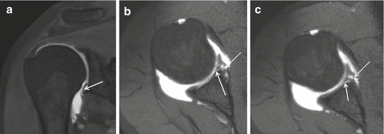
GARD lesion on 1 T D-MRA T1 FS. (a) Coronal and (b, c) axial images. Hyaline cartilage lesion (arrows) with Perthes lesion (thin arrows) demonstrated on axial images
-
Lesions may deteriorate in time. Perthes can change in Bankart or ALPSA. Labral lesions associated with inferior glenohumeral ligament complex lesions cause major instability (HAGL and BHAGL).
-
Glenoid avulsion of the IGHL (GAGL) is rare; characteristic is the inverted J sign.
-
In floating AIGHL and avulsion of the humeral and glenoid, attachment of the IGHL is present. The condition is more frequent in younger patients and coincides with Hill-Sachs lesion.


Midportion capsular tear accounts for 35 % of capsular tears and is located more posterior and often found after initial dislocation without labral tear. The lesion can be confused with contrast extravasation.
3.2.4 Adhesive Capsulitis
Adhesive capsulitis (frozen shoulder) is a clinical syndrome predominantly found in middle-aged females (40–60 years). The lesion is frequently underdiagnosed. Corticosteroid injections offer rapid pain relief in the short term (particularly in the first 6 weeks) for adhesive capsulitis. Long-term outcomes seem to be similar to other treatments, including placebo (Song et al. 2014). On MRI, I-MRA, and D-MRA the axillary pouch is small with thickening (>4 mm) of the capsule and IGHL and enhancement after IV Gd (Figs. 17.23 and 17.24). Due to capsule enhancement I-MRA offers increased conspicuity of thickening of the axillary capsule and IGHL compared to D-MRA and MRI. Real-time and dynamic US has a role in diagnosis of retractile capsulitis. Reduced endo- and exorotation capacity of the glenohumeral joint results in constant anterior location of the LHB and the intertubercular groove. Thickening and power Doppler signal of the synovium and capsule may be present at the LHB tendon sheath or at the RI (Corazza et al. 2015). Therapeutic imaging (US or CTA) guided joint distention with corticosteroid may be performed.

Adhesive capsulitis, 3 T I-MRA in a 67-year-old male patient. SLAP VIII lesion. Demonstration of thickening of the axillary capsule-IGHL (arrows) and rotator interval (thin arrow). Better demonstration on T1-FS compared to intermediate FS images. SLAP VIII lesion is demonstrated with paralabral cyst (thick arrows)

Adhesive capsulitis, US in a 48-year-old female. (a) Axillary image with shoulder elevation, (b) axial slice at the level of the LHB tendon sheath, and (c) axial image at the RI with maximal endorotation. Thickening of the capsule and synovium (arrows) with anterior location of the LHB (thick arrow) on maximal endorotation position
3.2.5 Posterior Instability
Posterior instability accounts for 5 % of instabilities. It is characteristic non-traumatic event that may cause recurrent posterior instability. The instability is multidirectional and related to seizures, electric shock, or adduction, flexion, and internal rotation movement. In 60 % labral lesions are present. Posterior labral tears greater than 15 mm are significantly associated with posterior instability. Posterior capsular laxity is the most common abnormality (Schwartz et al. 1987).
-
The dislocation may result in reversed Bankart lesion with labral tear and periosteal rupture but without cartilage lesion. Bone fracture fragment may be present as well as a reversed Hill-Sachs (McLaughlin). Fluid or contrast may extend behind the glenoid.
-
In Kim lesion deep intrasubstance incomplete detachment (marginal crack) of the posteroinferior labrum is associated with a defect at the chondrolabral junction. MRI depicts these lesions in a sensitive (85 %) and specific (75 %) way (Smark et al. 2014). This may lead to repetitive posterior instability with subluxation of the humeral head and shear forces between glenoid rim and labrum with failure of the chondrolabral junction. Kim lesion can be concealed at arthroscopy and is treated by converting it to complete tear and suture with an anchor.
-
Reversed or posterior Perthes (Fig. 17.25) may lead to POLPSA or posterior labroligamentous periosteal sleeve avulsion (posterior ALPSA) (when medially displaced) and predisposes to posterior instability (Fig. 17.26). This lesion is treated by reduction of the periosteal sleeve with attachment of the labrum.
Fig. 17.25 Fig. 17.26 
POLPSA 1 T D-MRA, older patient with glenohumeral osteoarthritis. Less conspicuous enhancement at the posterior inferior labrum (arrow). Chronic tenosynovitis LHB with stenosis: absence of contrast at tendon sheath, thickening of tendon sheath (thick arrow). Posterior capsule insertion (thin arrow)
-
In posterior glenoid labrum articular disruption (GLAD), a focal defect in the articular cartilage between 7 and 9 o’clock is present associated with labral tear but no instability.
-
PHAGL or posterior humeral avulsion of the IGHL is the posterior counterpart of HAGL. In BPHAGL associated bony avulsion is present. On MRI typically extra-articular contrast extravasation is detected.
-
In reversed GAGL glenoid avulsion of the posterior band of the IGHL is present. Bennett lesion is characterized with an enthesophyte that arises from the posteroinferior portion of the glenoid rim, probably from the insertion of the posterior band of the IGHL, and is sometimes associated with labral tears and undersurface RC tears (internal impingement). This lesion is common in baseball pitchers (25 %). Posterior capsular laxity is the most common abnormality seen with posterior instability (Fig. 17.26 thin arrow).


3.2.6 Multidirectional Instability
Multidirectional instability is a non-traumatic form of instability in multiple directions resulting from capsuloligamentous laxity related to soft tissue connective disorders (Ehler-Danlos, Marfan). It is found in young females and individuals with capsular laxity or hypoplastic glenoid labrum. The instability is atraumatic or related to a minor event associated with multidirectional laxity and with bilateral findings. Treatment is predominantly by rehabilitation directed at restoring optimal neuromuscular control. If surgery is necessary, it needs to include reconstruction of the rotator interval capsule-coracohumeral ligament mechanism and tightening of the inferior capsule (AMBRII (atraumatic, multidirectional, bilateral, responds to rehabilitation, inferior capsular shift, interval closure)). These patients have a lax capsule (difficult to quantify on MRI). Some have arthroscopic and MRA or CTA findings found in other instabilities like Hill-Sachs, greater tuberosity fracture, bony Bankart (indication for open repair), inverted pear-shaped glenoid, reversed Bankart, reversed Hill-Sachs (McLaughlin), and OCD of the glenoid fossa.
3.2.7 Instability Associated Bony Lesions
Bony lesions may be present in shoulder instability. Hill-Sachs is found in 75 % of patients with anterior instability. MRI is superior to arthroscopy for detecting Hill-Sachs lesions (Fig. 17.27a, b). Hill-Sachs is located in the top 2 cm of the humerus and located posterolaterally above or at the level of the coracoid process. Posterolateral depression of the humeral head in the most cranial CT or MR axial slice is most specific. Deep Hill-Sachs defect may elicit recurrent dislocation. This is caused by leverage action of the humeral impression that covers the anterior glenoid in endorotation position. Exorotation movement then results in leverage with dislocation.

(a, b) MRI Male patient with reduction of acute anterior shoulder dislocation, 2 weeks ago, Hill-Sachs defect detected on 3 T I-MRA. (a) Axial T1-WI FS and (b). sagittal T1-WI FS, bone marrow edema at the greater tuberosity, and humeral epiphysis surrounding depression of the cortical bone and subchondral lamella (arrows). Cranial extension of anterior Bankart lesion is depicted (a thin arrow)
Reversed Hill-Sachs has to be differentiated with cystic change or vessels in the “bare area” of the ISP that is a normal anatomic groove posterolaterally (located at long axis of humerus, 2 cm distal to top of humeral head).
Bony Bankart and reversed bony Bankart lesion may result in instability. Anterior bony Bankart fragment over 1/3th of glenoid AP diameter at the level of the center of rotation of the glenoid is associated with habitual dislocation (Figs. 17.16 and 17.28b) (Bhatia et al. 2011). Three-dimensional CT is most accurate to quantify bone deficiency (Griffin and Brockmeier 2015).

Pear-shaped glenoid. Drawing demonstrating calculation of percentage of bone loss
3.2.8 Microinstability
Microinstability is minor displacement of the humeral head without dislocation. Potential sites of involvement of microinstability are the anterior articular surface of the SSP tendon, the articular surface of the posterior SSP-anterior ISP tendon, the CHL, the intraarticular part of the LHB and biceps pulley, the SGHL, the deep fibers of the SSC tendon, the cranial part of the middle GHL, anterosuperior and posterosuperior part of the labrum, and the origin of LHB. Three different types are described: SLAC, superior labrum anterior cuff; ASI, anterosuperior impingement; and GIRD, glenoid internal rotation deficit. SLAC is defined as anterosuperior subluxation related to repeated overhead activity or related to acute trauma (fall, MVA (strap)). Typical sites of involvement are anterior glenoid, anterior biceps, SGHL (MGHL), and anterior articular PTT of SSP. Treatment is focused on reduction of instability.
3.2.9 Impingement
Impingement is subdivided in external (primary intrinsic) and internal (secondary intrinsic). Two types of external impingement are recognized: subacromial and subcoracoidal.
3.2.9.1 Internal Anterosuperior Impingement
Internal anterosuperior impingement produces pain in elevation and internal rotation, with impingement of the deep surface of the subscapularis (Gerber and Sebesta 2000; Habermeyer et al. 2004a, b) and a lesion at the biceps pulley resulting in instability of the LHB. The slight anterosuperior humeral head translation impinges on the glenoid with development of SSC/SSP partial articular sided tears and lesions in the anterosuperior portion of the glenoid labrum.
3.2.9.2 Internal Glenoid Posterosuperior Impingement
The act of overhead throwing causes pain related to impingement of the humeral head with the glenoid rim in abduction and external rotation. The slight anterior translation of the humerus during this act is the result of anterior capsule failure and causes impaction of GT and glenoid and impingement on the posterior SSP, anterior ISP, and posterosuperior labrum. MRI may reveal tears of the SSP-ISP (anterior infraspinatus partial undersurface tears), labral pathology with fraying, and tears including a variation of the type II superior labrum from anterior to posterior lesion, humeral head GT, and glenoid cystic lesions with cortical bone irregularities communicating with the articular cavity (Tirman et al. 1994a, b; Fessa et al. 2015). MRI in ABER position is useful (as the ABER position is in fact identical to the overhead abduction external rotation position that causes elongation of the anterior capsule IGHL and pain).
3.2.9.3 Glenoid Internal Rotation Deficit
Glenoid internal rotation deficit (GIRD) is found in throwing athletes. A posterior fibrosing capsulitis with thickening of the posterior band of the IGHL and associated anterior capsule stretching results in a slightly posterosuperior shifted center of rotation. This turns out in increased forces on LHB and anchor and superior labrum and a peel back mechanism with SLAP II lesion. On MRI a posterior capsulitis with thickening of the posterior capsule, a large labrum, SLAP II with extention posterior from the biceps and signs of internal posterior impingement are found. GIRD is treated by stretching of the capsule (conservative) or by arthroscopic repair with release of the posterior capsule.
3.2.9.4 External Subacromial Impingement
In this (most frequent) type of impingement abduction elevation of the shoulder causes progressive painful compression of the SSP, SD-SA bursa, and LHB between the humeral head and coracoacromial arc. Impingement on the tendinous portion of the rotator cuff by the coracoacromial ligament and the anterior third of the acromion is responsible for this frequent and characteristic syndrome of disability of the shoulder. A characteristic proliferative (keel) spur or enthesophyte has been noted on the anterior lip and undersurface of the anterior process of the acromion (Fig. 17.1b, c arrow); this area may also show erosion and eburnation. The impingement may also involve the tendon of the LHB, and if it does, it is best to decompress the tendon and remove any osteophytes which may be in its groove. Hypertrophic osteophytosis at the AC joint may impinge on the SSP tendon when the arm is in abduction (Neer 2005). According to Neer 95 % of RC tears at the level of its enthesis at the GT are the result of chronic subacromial impingement leading to tendinopathy and tears (Fig. 17.63). Clinical diagnosis is made by the Neer and Hawkins test. Osseous abnormalities are present at the level of the acromion: enthesophytes, anterior hooking (type 3 Bigliani Fig. 17.29. 3, Table 17.7), anterolateral inferior downsloping, and low position to distal clavicula. Also os acromiale (Fig. 17.31) and M. Paget (acromion or clavicle) are associated with subacromial impingement. At the level of the GT fracture with displacement or remodeling may cause a prominent GT resulting in subacromial impingement. Secondary soft tissue abnormalities are found in the SSP and LHB with tendinosis, PTT or FTT, thickened or ossified coracoacromial ligament, subacromial bursal thickening, and hypertrophied SSP muscle (Fig. 17.19). Calcifications at the SSP may be the result and increase the thickness of the tendon amplifying subacromial impingement. Three acromial types are described by Bigliani in 1986; type 3 is associated with impingement and RC tears (Fig. 17.29 and Table 17.7). Gagey added type 4 in 1993 (Fig. 17.30a, b) (Natsis et al. 2007). The acromion types are described on sagittal CT or MRI slices or scapular Y radiographs of the scapula (Figs. 17.29 and 17.30).

(1–3) External subacromial impingement, osseous abnormalities of the acromion, Bigliani types 1, 2, and 3 demonstrated on scapular Y view

(a, b) Type 4 acromion according to Gagey. (a) Sagittal CTA and (b) sagittal T1

Os acromiale. Radiographic demonstration of os acromiale (arrows) on AP view (a) and (b) scapular Y view. CT (c) and MRI (d) demonstration on axial slice
The types of acromial shape with the existence of enthesophytes together comprise two important parameters for subacromial impingement syndrome and rotator cuff tears. Enthesophytes were found mostly in type 2 (7.9 %) and type 3 (37.7 %) acromion (Fig. 17.29.1 and 2). The enthesophytes are localized at the site of the coracoacromial ligament insertion on the acromion (Fig. 17.1b, c). Enthesophytes were significantly more common in type 3 acromions, and this combination is particularly associated with subacromial impingement syndrome and rotator cuff tears (Natsis et al. 2007). Hooked acromion (type 3) may be congenital or acquired due to aging related to degeneration of the origin of the CHL; it is more common in males and mostly symmetric. Lateral downsloping acromion is related to impingement on the SSP in critical zone, also possibly on the SSC. Low lying acromion relative to the distal clavicula is present in os acromiale, which is a not fused accessory ossification center (junction of meta-, meso-, and preacromion). It may be the cause of shoulder pain itself; the contraction of the deltoid muscle may pull it down causing impingement. Os acromiale is bilateral in 60 % of cases. Subacromial impingement is treated conservatively, with coracoacromial ligament release, resection of the distal clavicula, or with anterior acromioplasty (Neer 1972, 2005). End stage subacromial impingement is defined as complete SST tear with retraction, cranial migration of the humeral head with bony conflict against the acromion, eburnation of the acromion, glenohumeral joint non-congruity resulting in glenohumeral joint osteoarthritis, and secondary subcoracoidal impingement (section “External subcoracoid impingement”).
3.2.9.5 External Subcoracoid Impingement
This type of impingement is related to compression of the subscapularis tendon and structures at the rotator interval between the coracoid process and the lesser tuberosity of the proximal humerus (in the coracohumeral interval). It may be due to congenitally elongated or angled coracoid process. Clinically anterior shoulder pain is present that is elucidated with forward elevation, internal rotation, and horizontal adduction of the humerus and is sometimes associated with a painful click. In sports primary external subcoracoid impingement is found related to slight distraction to the posterior glenohumeral shoulder capsule in the end stage of endorotation in racket swing or golf swing. The syndrome is easily overlooked, both clinically and with imaging. It is rarely isolated. The condition is treated with activity modification or coracoplasty. Normal coracohumeral interval distance is 8 mm in females and 11 mm in males. Stenosis related to subcoracoid impingement is defined as less than 6 mm. These measurements are not reliable; the diagnosis is made by clinical evaluation and anesthetic infiltration. Bone marrow cystic and reactive changes in the LT or coracoid tip with SSC tendinosis and (partial thickness) tears may be found (Fig. 17.5a, b long arrow). Subcoracoid impingement is most frequently found as end stage of subacromial impingement with cranial migration of the head of the humerus in complete SSP tear with retraction leading to decreased distance of the coracoid process and the humerus. This mechanism defines the biphasic evolution of subacromial impingement, in the first stage with clinical signs of subacromial impingement and in a second stage the clinical signs of subcoracoidal impingement.
3.3 Labrum, SLAP, and Biceps Lesions
Imaging plays an important role in the diagnosis of superior labrum anterior to posterior (SLAP) tears. Knowledge of glenolabral anatomy, related structures, and variants, proper imaging techniques, and a systematic approach to MRI interpretation are important in the diagnosis and treatment planning of the ten types of SLAP lesions. Arthroscopy offers definitive diagnosis (Modarresi et al. 2011a, b).
3.3.1 SLAP Lesions
The arthroscopic prevalence of SLAP lesions in a population with shoulder pain ranges from 3.9 to 11.8 %. Surgeons use mostly the 4 original described types centered at the attachment of the LHB tendon (Snyder et al. 1990) (Table 17.8 and Figs. 17.23a, 17.32, and 17.33). Isolated LHB tears are rarely anterosuperiorly located. Tears are usually associated with SLAP lesions or tears that extend anteroinferior in the labrum. In current literature there is no sufficient support that MRI can accurately differentiate all SLAP lesions. Different mechanisms are related with SLAP lesions: SLAP I is related to degenerative labrum with aging; SLAP I and II are related to repetitive overhead motion: SLAP II, IV (Fig. 17.32a, b), and V are related to falls on outstretched hand; SLAP V and VII are related to glenohumeral instability. A practical approach to radiological diagnosis of SLAP lesions is to describe the location using clock face or quadrants, define if the biceps tendon is involved, and describe the anterior-posterior extension and the morphology of the lesion: fraying versus tearing. Displaced (bucket handle) or free fragments and associated lesions or extension in the MGHL or anteroinferior labrum (implies GH instability and different surgical treatment) should be mentioned.

SLAP IV. 3 T I-MRA T1 FS coronal slices (a, b) demonstrating gadolinium enhancement at the labrotendinous junction with lateral distention into the biceps (arrows)

SLAP VIII. Anterior and posterior labrocartilaginous disruption (arrows) demonstrated on axial 1 T D-MRA T1 FS Bigliani and Vanarthos acromion types
3.3.2 Labral Cysts
Labral cysts typically arise through labral tears and may cause nerve compression. The suprascapular nerve may be compressed at the level of the suprascapular foramen below the transverse ligament with denervation of the supraspinatus and infraspinatus muscle. If the cyst is located at the spinoglenoid notch, the suprascapular nerve is compressed more distally with denervation only of the infraspinatus muscle (Fig. 17.23 thick arrow mid lower position, Figs. 17.34, 17.35, and 17.36). The axillary nerve may be compressed in inferior location of the labral cyst causing denervation of the teres minor and deltoid muscles.

Paralabral cyst with denervation of ISP muscle, 1 T D-MRA. (a) Coronal T2-WI demonstrating high SI cyst at spinoglenoid notch (arrow) with compression of the distal part of the suprascapular nerve. (b) Axial T1-WI FS demonstrating global enhancement (arrows) of ISP muscle related to early denervation (first 3 weeks)

Labral cyst at spinoglenoid notch. 1,5 T I-MRA (a) coronal intermediate TE FS and (b) coronal T1-WI FS, (c, d) sagittal intermediate TE FS in spinoglenoid notch (d) and more laterally at the cyst stalk (c). Specific location at spinoglenoid notch is best demonstrated on sagittal images (arrows). No denervation signs at infraspinatus muscle belly

US demonstration of fatty involution of ISP in a male professional volleyball player without paralabral cyst at the spinoglenoid notch (Courtesy of FYZZIO, the Netherlands). Marked global increased reflectivity grade II according to Strobel (Table 17.15) of the ISP muscle is obvious when compared with trapezius and teres minor muscle
On D-MRA the cyst often is not filled with contrast and remains with low SI on T1-WI FS. Muscular denervation edema or muscle enhancement with IV gadolinium administration may be present (I-MRA) on T1 FS (Fig. 17.34b) and increased muscle signal on PD and T2 (FS) images on D-MRA and I-MRA. I-MRA T1-WI FS may show contrast enhancement in the wall/surrounding tissue of the cyst. Denervation edema or contrast enhancement on T1-WI FS is found in early stages (within the first month) of denervation. In late stages fatty infiltration in the muscle is detected on MRI and ultrasound (Fig. 17.36).
Denervation of ISP muscle without labral cyst is a specific finding in elite volleyball players (Fig. 17.36).
3.3.3 Biceps CL Tendon Lesions
3.3.3.1 Tendinopathy and Tenovaginitis
In LHB tendinosis MR shows brightening in the tendon on T1 without high T2 SI; one should be careful to discriminate magic angle phenomenon (at 54.7° relative to B0 magnetic field of 1.5 T Sect. 17.3.4.3) specifically on the turn into the groove (Fig. 17.37). The tendon can be swollen in the intracapsular portion (“hourglass” tendon) producing a mass effect with incarceration (Fig. 17.37b). Major sign on US is focal thickening of the tendon (Fig. 17.38). The mechanism of tendinopathy of the biceps is subacromial impingement of the tendon in RC tears with subacromial osteophytes in the bicipital groove or subluxation or medial dislocation of the tendon. Bone marrow edema can be found at the level of the intertubercular groove. Increased fluid in the tendon sheath without associated increased glenohumeral joint fluid is found. Associated stenosing tenosynovitis and adhesions with lack of contrast passage to the synovial tendon sheath may be found (Fig. 17.26 thick arrow). Inflammatory arthropathy (RA) may cause tenosynovitis of the LHB tendon sheath.

Intraarticular LHB tendinopathy, I-MRA demonstration. 1 T I-MRA with (a) coronal intermediate TE FS and (b) axial T1 FS slices demonstrating increased SI and thickened (hourglass aspect) of the tendon (b arrow)

LHB tendinopathy at intertubercular groove, US demonstration. Axial US images at the junction of RI and intertubercular groove, left image demonstrating thickened LHB (0.56 cm) compared to right LHB (right image) with thickness of LHB of 0.42 cm
3.3.3.2 LHB Tear
LHB tendon rupture is usually related to preexisting tendinosis. Musculotendinous rupture of the healthy tendon is related to severe trauma (weight lifters). Patients complain of an audible “pop” followed by Popeye sign with distal retraction of the muscle belly. Partial tears are documented on US or MRI with thinning, irregularity, fragmentation, and high SI of the tendon. A longitudinal fissure should be discriminated from a constitutional bifid tendon (Figs. 17.13a, b and 17.39a, b). Most tears are located proximal in the intertubercular groove. Neer discriminated three FTT types: type I, tear without retraction (Fig. 17.40); type II, tear with retraction; and type III, self-attaching tear without retraction. The radiologist should describe the location of rupture and retracted stumps. In case of distal retraction the tendon is absent in the intertubercular groove. Proximal from the intertubercular groove the stump can move in the RI which may cause glenoid and humeral head chondromalacia. The sensitivity for lesion detection of biceps CL lesion for CT arthrography was 31 % and the specificity 95 % which is comparable with the sensitivity for MRA arthrography that was 27 % and the specificity 94 %. There were no statistically significant differences between CT and MR. The interobserver agreement calculated with the kappa statistic was poor for CT and for MR. Both CT arthrography and MR arthrography perform poorly in the detection of biceps tendon pathology of the shoulder.

Split long head of the biceps with LHB tendinopathy at the posterior part and longitudinal split at the intertubercular groove, US demonstration with probe position. Axial (a) and longitudinal (b) images demonstrating three structures at the intertubercular sulcus, split anterior LHB (small arrow) and thickened posterior LHB with the longitudinal split (long arrow)

Partial-thickness LHB tear (type I tear according to Neer), 3 T I-MRA demonstration. (a) Oblique axial T1-WI FS and (b) sagittal T1-WI demonstrating central gadolinium enhancement at the tendon at the RI (b) and at the intertubercular groove (a). Thickening of the midportion of the biceps pulley at CHL level (short arrows). Tear at the LHB (long arrow a and b)
3.3.3.3 LHB Subluxation and Dislocation
The biceps pulley or “sling” is a capsuloligamentous complex that acts to stabilize the long head of the biceps tendon in the bicipital groove. The pulley complex is composed of the SGHL, the CHL, and the distal attachment of the SSC tendon and is located within the RI between the anterior edge of the SSP tendon and the superior edge of the SSC tendon (Fig. 17.41). Because of its superior depiction of the capsular components, D-MRA is the imaging modality of choice for demonstrating both the normal anatomy and associated lesions of the biceps pulley. Oblique sagittal images and axial images obtained with a high image matrix are valuable for identifying individual components of the pulley system (Figs. 17.41 and 17.42). Various pathologic processes occur in the biceps pulley as well as the RI. These processes can be traumatic, degenerative, congenital, or secondary to injuries to the surrounding structures. The term “hidden lesion” refers to an injury of the biceps pulley mechanism and is derived from the difficulty in making clinical and arthroscopic identification (Habermeyer et al. 2004b). Subluxation and luxation of the LHB tendon is frequently encountered. LHB dislocations are demonstrated on US and MRI, with the possibility of dynamic examination on US. In subluxation some contact with the intertubercular groove exists; in dislocation there is no contact with the groove. Three categories are described: tendon displacement (type I, II, and III Figs. 17.43, 17.44, and 17.45), the extra-articular dislocation (type IV Fig. 17.46), or intraarticular displacement (type V and VI Figs. 17.47 and 17.48). Six types are defined (modified Habermeyer classification) (Habermeyer et al. 2004b) (Table 17.9 and Figs. 17.43, 17.44, 17.45, 17.46, 17.47, and 17.48). A partial intrasubstance tear of the SSC with intact pulley can result in minimal medial shift of the biceps tendon, type I Habermeyer biceps dislocation (Fig. 17.43).

Biceps pulley at the entrance of intertubercular groove. US with probe position, D-MRA demonstration. (a) Oblique axial US and (b) oblique axial MRA T1- WI FS demonstration of posterior sling of biceps pulley (CHL) (arrows) with schematic drawing. LHB is covered with TL (thick arrows)

(a–c) Biceps pulley demonstration on D-MRA. Oblique sagittal D-MRA T1-WI A. Medial slice near origin of LHB, CHL, and SGHL until C. Lateral near to entrance of intertubercular groove. LHB (thin arrows), CHL (thick arrows), and SGHL (long arrows). (c) Demonstration of connection of CHL with rotator cable (thick arrow). RI: double-sided dotted arrows

LHB type I instability, US demonstration with schematic drawing. Partial intrasubstance tear of SSC with intact pulley and minimal shift of the biceps. Thickening of the LHB pulley at the interval area (a cross marks) with medial off center location of the biceps (a thin arrows) and widening of the interval up to 13 mm (b cross marks). Difficult differentiation from LHB type III instability

LHB type II instability. Schematic drawing. Intact SSC attachment but medial tear of biceps pulley with medial subluxation of the biceps tendon

LHB type III instability. Schematic drawing and US and D-MRA demonstration in different patients. Intrasubstance tear of SSC with medial pulley tear (double-sided arrow) and extra-articular medial subluxation of LHB. (a) axial CTA and (b) axial anterior US in different patients

LHB type IV instability. Schematic drawing and I-MRA and US demonstration in a 31-year-old female. Rupture of the pulley is located at the lateral limbs; associated tear of TL (double-sided arrows) with extra-articular migration of the biceps that is located anterior to the intact SSC

LHB type V instability. Schematic drawing. Full-thickness tear of SSC with medial pulley tear and medial intraarticular dislocation of the biceps

LHB type VI instability. Schematic drawing with CTA demonstration. Detachment of the SSC with intact continuing fibers to TL and GT, medial biceps pulley tear with medial intraarticular dislocation of LHB
3.4 Rotator Cuff
3.4.1 Ultrastructure of the Rotator Cuff
The rotator cuff tendons are histologically heterogeneous. They are assembled of up to four layers depending on the overall direction of collagen bundles, the fifth layer is the shoulder capsule. The major and superficial or bursal layer of the cuff has collagen bundles parallel to the overall direction of the tendon (layer II). Deep to this, layer III, has no prominent bundle direction, whereas layer IV the cable or transverse band has a bundle direction perpendicular to layer II. The cable is also known as ligamentum semicirculare humeri. The cable is located adjacent to the glenohumeral joint capsule (V) (Table 17.10) (Figs. 17.49a, b and 17.50a, b). The cable represents a thickening at the articular side of the tendon located approximately 1–1.5 cm medial to the enthesis (footplate) of the tendons which is the area of relative hypovascularity also known as critical area of the SSP and ISP. The rotator cable and crescent are located in the distal SSP and ISP tendon only (Fig. 17.50) (Burkhart et al. 1993). The cable starts anterior at the level of the intertubercular groove to end posteriorly at the level of the teres minor enthesis (Fig. 17.50a, b). It is regarded as a deep extension of the CHL by Clark and Harryman (Fig. 17.42c) (Clark and Harryman 1992). The crescent is the part of the tendon between enthesis and cable (Figs. 17.50a, b and 17.42c). Mean thickness of the crescent is 1.82 mm and of the cable 4.72 mm (Burkhart et al. 1993). The anatomical thickening of the cable is variable and may be detected on imaging in cable-dominant cuffs (Fig. 17.51). In cable-dominant cuffs the thick rotator cable acts as a suspension bridge preventing tears at the crescent to widen; it reduces the functional impact of cuff tears (PTT and FTT). Most of the cuff tears are allocated at the crescent; these are typically the tears related to subacromial impingement. The different layers of the cuff are not detected on MRI (Fig. 17.51a). High-resolution US may detect layer II, III, and IV (cable) (Figs. 17.51 and 17.52a). Cuff tears located at the cable itself are located at the critical area and result in more important retraction and functional cuff disability. Also cuff tears at the crescent in non-cable-dominant cuffs result in more retraction.

Ultrastructure of rotator cuff. Schematic drawing

(a, b) Rotator cable and crescent. Schematic drawing. (a) Posterior shoulder and (b) cranial view. Contours of bony landmarks of proximal humerus and scapula (thick lines). Contours of soft tissue landmarks of ISP and SSP (thin lines). Location of the cable (dotted structure) perpendicular to the direction of the tendons. Crescent is the distal part of the tendon, width 1 cm, located between cable and enthesis (double-sided dotted arrows)

Rotator cable, US demonstration. US SSP at RI with demonstration of cable (arrows) continuity with CHL (thick arrows), for comparison similar view on Fig. 17.42c

Thickened SSP in tendinopathy demonstrated on US. (a) Longitudinal US view of normal SSP tendon with demonstration of layer II and III (arrows). (b) Longitudinal US view of focal thickening with hyposonant aspect related to tendinopathy of the SSP tendon. (c) Longitudinal and (d) axial US view in another patient
3.4.2 Tendinopathy
Focal thickening of a tendon is a major sign of tendinopathy (Fig. 17.52b). Tendinopathy is essentially a degenerative process (no prominent inflammation) related to impingement or overuse. Tendinitis is a misnomer as tendon inflammation is not prominent. Intrinsic tendon lesions related to overuse or acute traumatic tear are located at the “critical area,” mid-tendinous, with critical vascular supply. In subacromial impingement the insertional area or enthesis of the SSP and ISP at the GT is involved. Focal structural anomaly in tendinopathy is detected on MRI with increase SI or on US with decreased reflectivity. Structural hyporeflective anomalies on US should be detected on longitudinal and transverse imaging (Fig. 17.52c, d). The subacromial bursa may be thickened with or without fluid accumulation; inflammation is not prominent; this bursa thickening is most prominent at the area of impingement and demonstrated on US and MRI on PD FS or T2 FS series but not on T1 FS series in D-MRA (Fig. 17.53). Gadolinium DTPA enhancement is demonstrated on I-MRA (Fig. 17.54). Tendon calcifications are caused by hydroxyapatite deposition (HADD) and may have low SI on all MRI pulse sequences (Fig. 17.54). Intratendinous calcifications are not discriminated from low SI collagen and can easily be missed on MRI. US and radiographs are more accurate to detect RC calcifications (Fig. 17.55). Clinically four stages of calcifying tendinopathy are described (Table 17.11). Most often calcifications are silent without clinical complaints (phase 1). In phase 2 when the calcification causes bulging on the bursal aspect of the tendon, pain with movement is related to tendon and SA-SD bursa impingement. For example, pain during glenohumeral elevation-abduction “painful arc” is found in SSP calcifications. Pain during glenohumeral endorotation movement is characteristic for SSC calcifications. Subbursal (phase 3) and bursal (phase 4) with extrusion of the calcifications is characterized by bursitis with acute inflammatory pain (Fig. 17.54).

Fluid at the SA-SD demonstrated on US. Asonant area of fluid (double-sided arrow) at the SA-SD bursa superficial to SSP and deep to deltoid muscle area

Fluid at the SA-SD bursa and SSP calcifications demonstrated on I-MRA. (a) Coronal T1-WI FS, (b) coronal intermediate TE FS, (c) sagittal T1-WI, (d) axial T1-WI FS. Calcifications with low SI on all sequences (thin arrows), partial extrusion of the calcification to the SA-SD bursa (d thin arrow). Fluid (thick arrows) at the SA-SD bursa with enhancement on T1-WI (a–c) and high SI on fluid sensitive sequences (b)

Calcification at SSP demonstrated on US and radiograph. (a) Coronal view and (c) sagittal view on the SSP with hyperreflective calcification with acoustic shadowing and enlargement of the cuff. Demonstration of dense calcifications on 3/4th view (b) and scapular Y view (d)
3.4.3 RC Tears
Tendon tears are characterized by discontinuity of collagen bundles. Bundle discontinuity is directly demonstrated on US. Fluid in the tendon will be detected on MRI. In case of high SI in a tendon on fluid sensitive MRI sequences (T2, intermediate TE, and PD with and without FS) tendinosis has to be discriminated from artifacts (motion, vessels, metal, etc.), HADD with high SI (calcium milk phase), immediate postoperative status or after recent tendon platelet-rich plasma (PRP) injection or percutaneous needle tenotomy (PNT) procedure. High SI on PD and T1-WI in tendons can be caused by tendinopathy and should be discriminated from magic angle phenomenon, fibrosis, and granulation tissue in tear and is found in the ISP in internal rotation position (overriding the SSP), it is also a normal finding in children and adolescents. Increased SI related to magic angle phenomenon is specifically found in sequences with short TE (shorter than 37 ms on 1.5 T (T1 and PD)) in tissues with well-ordered collagen fibers in a single direction (tendon, ligament, cartilage) with an angle of about 50° with the permanent magnetic field B0 (54.7° in 1.5 T). Discrimination of magic angle phenomenon and tendinopathy is done by comparison of T2-WI (with long TE) in which the magic angle artifact disappears.
3.4.3.1 PTT
PTT and FTT are discriminated through a direct communication of the SA-SD bursal space with the glenohumeral joint in FTT (Fig. 17.62). In D-MRA an injection of the glenohumeral joint results in opacification of the SA-SD bursa in case of FTT. This D-MRA sign is void in I-MRA. PTT are twice as frequent compared to FTT. PTT can be located at the bursal side, at the articular side, or intrasubstantial in the tendon. Morphologic features of tears should be described: location in long axis and short axis with dimensions, characteristics (vertical, horizontal, oblique, thinning, irregularity, delamination, articular sided retraction, undersurface flap). Low-grade PTT have a depth of less than half of the tendon thickness (Fig. 17.56), medium-grade PTT are half of the tendon thickness, and high-grade PTT are more than half of the tendon thickness (Fig. 17.57). On arthroscopy PTT are staged differently (Table 17.12) (Millstein and Snyder 2003).

Low-grade bursal sided PTT at SSP demonstrated on US. Longitudinal US of low-grade bursal sided PPT at SSP (arrows)

High-grade bursal sided PTT at SSP crescent demonstrated on US. Transverse (a) and longitudinal (b) with discontinuity of tendon fibers (arrows) filled with asonant fluid
Articular sided PTT are the most common; they are associated with GH instability, microinstability, and internal impingement (Fig. 17.58).

Medium-grade articular sided PTT at critical area (cable) demonstrated on 1.5 T D-MRA. Coronal T1-WI FS demonstrating gadolinium infiltration at thinning of the SSP tendon in the area of the tendon
Bursal sided tears are more related to extrinsic impingement. Bursal puddle sign is recognized (bursal sided fluid SI continuous with the SA-SD bursa) in bursal sided PTT (Figs. 17.56 and 17.57).
Intrasubstance PTT are typically delamination or loosening of the different tendon layers and may be missed on arthroscopy. MRI presents with low to intermediate SI on T1-WI and PD and with high SI on T2, PD FS, and T2* (PTT and degeneration present with similar signal) (Figs. 17.59 and 17.60). On D-MRA at the glenohumeral joint, articular sided PTT and FTT are demonstrated. Tears are understaged when there is granulation tissue in the tear. D-MRA will not demonstrate bursal sided PTT on T1-WI; they are only detected on the T2 or intermediate TE WI (Fig. 17.60a, b). I-MRA will demonstrate bursal sided PTT on T1-WI (Fig. 17.61).

PTT intrasubstantial delamination of SSP in 68-year-old women demonstrated on I-MRA and US. (a) Coronal T1-WI FS and (b) coronal intermediate TE FS longitudinal high-intensity area at SSP (arrows). (c) Longitudinal hyporeflective area between level II and III of the SSP

SSP PTT bursal sided demonstrated on 1 T D-MRA and US. (a) Coronal T1-WI FS, no demonstration of the tear. (b) Coronal intermediary TE FS demonstrating puddle sign. (c) Longitudinal SSP view

PTT bursal sided with delamination of SSP in 61-year-old women demonstrated on I-MRA. Coronal T1-WI FS with delamination (arrows) containing HADD (thick arrow). Extrusion of HADD at bursal side (small arrows) with irregular bursal margin of the tendon at the enthesis and partial cover of the GT footplate
A rim rent tear is an articular side PTT of the SSP at its attachment to the GT. These lesions start where the loads are greatest, i.e., the articular surface of the anterior SSP (Fig. 17.62). This lesion is more frequent in younger people and is associated with erosions and cystic changes. They can easily be missed on the coronal images. If the footprint is exposed over 7 mm lateral from the cartilage edge, this lesion is surgically repaired.

Rim rent PTT at SSP demonstrated in a 66-year-old female on glenohumeral CTA. (a, c) Axial and (b, d) coronal slices with anterior articular sided SSP tear (long arrows) with delamination enhancement of the tendon medial-posterior (small arrows). Small full-thickness tear is located anterior (thick arrow) with enhancement of SA-SD bursa
A rim rent lesion evolves into a PASTA (periarticular articular sided SSP tendon avulsion), i.e., a type of Snyder stage 2 or 4 articular surface delamination tear with significant fragmentation or flap. It is more common in younger people and overhead sports (Fig. 17.63). Reversed PASTA lesion is a selective delamination of the bursal surface of the SSP.
PTT and FTT can extend into the longitudinal tendon plane by delamination of the layered structure of the RC (Figs. 17.60, 17.61, 17.62, 17.63, and 17.64).

PASTA PTT at SSP demonstrated on glenohumeral D-MRA. Gadolinium enhancement at SSP enthesis with broad retraction of the SSP from the medial part of the footplate (arrows) and enhancement of intratendinous delamination area. No enhancement of the bursa in articular sided PTT

Schematic drawings demonstrating the progression of subacromial impingement related PTT in FTT. In the first stage SSP PTT evolves into FTT (stage II) with complete tear and retraction of the tendon (III). In the last stage cranial migration of the humerus causes impingement of ISP posteriorly and LHB and SSC anteriorly (subcoracoidal external impingement) with tendinopathy and tears as a result. This is clinically known as the biphasic evolution starting with subacromial impingement complaints and subsequently subcoracoidal impingement complaints
As a result of the low therapeutic consequence of non-detection of low-grade partial-thickness RC tears, US is regarded as the primary investigation tool. Major diagnostic advantage of US over MRI is the dynamic evaluation of impingement during elevation or endorotation. The LHB in its extra-articular and distal RI course is accurately demonstrated on US.
3.4.3.2 FTT and Complete Tears
PTT may evolve to FTT (Fig. 17.61). The mayor advantage of direct arthrography is the communication of the glenohumeral joint space through the RC with enhancement of the SA-SD bursa; this is pathognomonic for FTT (Fig. 17.65b, c). FTT are in early stages frequently located anterior in the SSP and propagate to the posterior aspect of the RC; 40 % extend into the ISP. Anteriorly they propagate to RI, LHB, and SSC. The size of the lesion should be reported in two dimensions, longitudinal and transverse (Figs. 17.66 and 17.67).

(a–c) US and arthrography and CTA demonstration of small FTT at footplate of SSP tendon in a middle-aged woman. Small erosion at the GT footplate often is a landmark for tendon disease; small FTT tear (arrows) is demonstrated on US (c), arthrography (b), and CTA (a) with demonstration of contrast enhancement at the SA-SD bursa (thick arrow)

I-MRA demonstration of small FTT at footplate of SSP tendon. (a) Coronal intermediary TE FS and (b) coronal T1-WI FS imaging plane

(a, b) FTT at critical area of SSP in a 65-year-old female patient. Fiber discontinuity filled with assonant fluid about 1.5 cm proximal to the enthesis of the SSP tendon is demonstrated in sagittal (a) and coronal plane (b). Coronal plane demonstrates hyperreflective cartilage sign related to fluid-cartilage interface (arrows) at the area of tendon retraction stage 2 according to Patte, Table (17.13)
A FTT with extension into the whole tendon is a massive or complete tendon tear; in these, the tendon may retract with lipomatous involution of the dependent muscle as a result. Arthroscopic stages of FTT are listed in Table 17.13. Tendon retraction should be reported and is staged on MRI or CT according to Goutallier or Patte (Lippe et al. 2012) (Table 17.14).
Tears dominantly located at the cable show less retraction and are easier to repair compared to lesions located at the crescent of the RC where retraction is more medial and repair more difficult (Fig. 17.68b; for comparison Fig. 17.50). Articular sided PTT with extension into the cable are more symptomatic compared to bursal sided PTT (Fig. 17.69a) (Burkhart 1992; Burkhart et al. 1993; Halder et al. 2002; Su et al. 2009).

(a, b) Schematic drawings illustrating suspension action of rotator cable. (a) Tear located at crescent results in minor tendon retraction related to transverse fortification. (b) Tear with disruption of the cable results in marked tendon retraction

(a, b) Complete SSP tear demonstrated on US. Sagittal (a) imaging plane with fluid at subdeltoid area anterior up to LHB and posterior up to ISP (arrow). Coronal (b) imaging plane demonstrates small tendon stump (arrow) at medial part of GT footplate. The retracted SSP tendon is not visible; it is retracted beyond the right margin of the image until the glenoid margin (stage 3 according Patte, Table 17.13)
Although interobserver reliability is low, rotator cuff muscle atrophy has to be graded according to Goutallier and/or Warner (Table 17.15). In Goutallier’s system muscle fatty infiltration is graded on sagittal CT images (Goutallier et al. 1994, 1999). Strobel defined accuracy of US in grading of SSP and ISP fatty atrophy (Strobel et al. 2005) and calculated a moderate accuracy of US of 75–85 % for SSP and ISP, respectively (Fig. 17.36). Assessed US parameters were visibility of muscle contour, visibility of pennate pattern, visibility of the central tendon, and muscle echogenicity (Table 17.16). In Warner’s classification muscle volume is related to a tangent line on sagittal images at the level of the coracoid process (MRI or US) connecting the cranial cortical margin of the spina with the cranial cortical lining of the coracoid process for the supraspinatus and of the posterior cortical margin of the spina with the posterior-inferior margin of the scapula for the infraspinatus muscle (Fig. 17.70a) (Warner et al. 2001; Tingart et al. 2003; Lippe et al. 2012).

(a–c) Complete SSP and ISP tendon tear with stage 3 retraction demonstrated on I-MRA. (a) Sagittal T1-WI demonstrating increased fat at the SSP and reduced muscle volume according to Warner below the cranial tangent lining of the scapula. Cranial half of ISP muscle also reveals increased SI related to fatty involution but without major muscle volume decrease (posterior tangent lining of the scapula). (b) Coronal intermediary TE FS image with retraction of the SSP tendon (arrow) stage 3 according to Patte, Table 17.13c. Axial T1-WI FS demonstrating retraction of the ISP tendon (arrow) stage 2 according to Patte
3.5 Postoperative Shoulder
Postoperative MRI of the shoulder is subject to artifacts that hamper interpretation of the images (Table 17.17). Metal artifact reduction sequences (MARS) are used to enhance MR image quality but have the drawback that gradient imaging and FS is avoided. MARS protocol includes SE or TSE sequences with view angle tilting, increased TSE factor (max 4TE), increased slice selection gradient strength with reduced slice thickness, and reduced ratio of FOV and pixel number in phase encoding direction and STIR instead of FS (Table 17.18) (Petersilge et al. 1996; Olsen et al. 2000; Chang et al. 2001; Lee et al. 2001). Moreover anatomic evaluation of tendon and labrum repair is prone to erroneous conclusions on CTA, US, and MRI. US and CTA are good alternatives to MRI for the evaluation of the postoperative cuff. CTA is a good alternative for the evaluation of labrum repair.
3.5.1 RC Repair
Articular PTT that do not involve more than two-thirds of the tendon thickness respond well to debridement of the necrotic torn tissue, with or without anterior acromioplasty. Full-thickness tears can require open surgery. Arthroscopy-assisted (mini-open) rotator cuff repairs or purely arthroscopic repairs are possible in some tears. Open repair offers the best exposure of the lesion for the surgeon, but this procedure prolongs recovery time. Mini-open repair technique includes a vertical spit in the deltoid muscle with arthoscopic acromioplasty and RC repair. Pure arthroscopic repair offers the fastest rehabilitation but is surgically challenging for large tears (double-row suture is difficult).
In PTT surgical debridement of granulation tissue is performed. In FTT or massive tears tendon to tendon repair is performed with single- or double-row sutures (Fig. 17.71). Tendon to bone repair is done with use of bioresorbable anchors (radiolucent) or with metal anchors.

End to end SSP tendon repair demonstrated on 1 T D-MRA. Increased SI on coronal PD WI FS with small low SI blooming artifact at area of suture (arrow)
Complications of cuff repair (retear 6.2 %, nerve injury 1.1 %, infection 1.1 %, deltoid dehiscence 0.5 %, frozen shoulder 0.5 %) may be indications for imaging. Deltoid dehiscence or detachment of the deltoid muscle from the acromion with pain and weakness on arm abduction is early postoperatively detected and has to be discriminated from retear (Fig. 17.72). MRI of tendon repair shows intermediate to low SI in the tendon related to granulation tissue and fibrosis, respectively (Figs. 17.71 and 17.72); with disturbed fibrillation on US, the morphology of the tendon is regular or irregular on MRI or US depending on the procedure and the tissue quality of the tendon related to preexistent tendinosis. Only 10 % of repaired tendons have a normal appearance on MRI. Mild superior subluxation of the humeral head may be related to capsular tightening, scarring, cuff atrophy, or bursectomy. Fluid in the subacromial-subdeltoid space is a nonspecific postoperative finding. “Geyser sign” on postoperative MR images is a common finding secondary to injury of the acromial undersurface during surgery. Bioabsorbable sutures and anchors are increasingly used. They produce a signal void with small artifact, may be C shaped, and dissolve over time (Figs. 17.71 and 17.72). Release of the components in the joint is not necessarily abnormal. Fluid or contrast under the tendon repair area with displaced anchor may be a sign of too early resorption. Small full-thickness defects with communication of the glenohumeral joint and the SA-SD bursa are normal. Pathologic communications are larger than 1 cm and have retracted tendon with progression in follow-up examinations, anchor displacement, muscle atrophy, large amounts of fluid in the SA-SD bursa, and GH OA. MRA may produce misleading results through enhancing granulation and scar tissue at tendon anastomosis. Ultrasound may be used to evaluate the integrity of a repaired rotator cuff tendon and constitutes a comparable alternative to MRI when evaluating the integrity of a rotator cuff repair. Clinical investigators should compare their postoperative ultrasound results with their postoperative MRI results for a certain time period to establish the accuracy of ultrasound before relying solely on ultrasound imaging to evaluate the integrity of their rotator cuff repairs (Codsi et al. 2014).

Deltoid dehiscence after end to end cuff repair on 1 T D-MRA. Coronal intermediate T FS image demonstrating normal cuff but absent deltoid muscle
3.5.2 Acromioplasty
Arthroscopic subacromial decompression is the method of choice for treatment of chronic extrinsic impingement. This procedure includes resection of the coracoacromial ligament (recently this ligament is preserved or reattached), anterior and posterior acromion resection, resection of acromioclavicular joint osteophytes, and, if necessary, distal clavicular resection. Evaluation of acromioplasty is done on sagittal images, except for the resection of the distal clavicula that is better evaluated on the axial imaging plane and results in widening of the acromioclavicular distance by 1–2 cm. Postoperatively the undersurface of the acromion resembles Bigliani type I.
3.5.3 Surgery for Instability
Bankart repair includes anteroinferior labral capsular repair. The anterior-inferior capsule may be shifted through inferior capsular shift procedure or with arthroscopic thermal shrinkage. The Latarjet procedure includes anterior glenoid bone augmentation by the coracoid process including the short head of the biceps and coracobrachial muscle origin and is performed in case of failed capsular reconstruction. The short head of the biceps acts as a stabilizator in abduction and exorotation. Capsular thickening is a common finding after surgical repairs of instability and labral tears. In nonanatomic reconstructions labral and capsular lesions are not directly repaired, and abnormalities due to these lesions are still visible on postoperative post repair MRI.
4 Accuracy of MRI Compared to US
The diagnostic performance of C-MRI, D-MRA, and US may be similar for detection of any rotator cuff tears (Table 17.19) (Rutten et al. 2010). However, C-MRI, MRA, and US may have poor sensitivity for detecting (low-grade) partial-thickness tears, and the sensitivity of US may be much lower than that of MRI (Lenza et al. 2013).
D-MRA and I-MRA show comparable sensitivities and specificities for rotator cuff and glenoid labrum pathology (Vahlensieck et al. 1998; Fallahi et al. 2013). We also found a high accuracy of I-MRA for FTT of the RC but lower accuracy (76–77 %) for PTT with lowest accuracy for low-grade tears at the bursal side. The major cause of error is the discrimination of tendinopathy and low-grade partial-thickness tear (Van Dyck et al. 2009). Obvious diagnostic advantages of I-MRA in comparison with direct arthrography are the detection of pathology through tissue enhancement: for example, the thickened and enhancing capsule in retractile capsulitis, thickening and enhancement of the SA-SB wall in subacromial bursitis, and enhancement of the wall of arthrosynovial ganglia.
MRA (direct and indirect) is the most accurate and sensitive available imaging method for the detection of labral tears (glenoid labrum, Bankart, and SLAP lesions). I-MRA is more and more regarded as a standard practice in patients with shoulder instability due to suspected labral pathology where further investigative imaging is indicated (Fallahi et al. 2013).
Recently comparable accuracy for anteroinferior labroligamentous lesions and SSP PTT was calculated comparing single D-MRA in ABER position and D-MRA by trained radiologists reducing the added value of ABER position (Schreinemachers et al. 2009).
MRA in the ADIR position provides high accuracy for the diagnosis of ALPSA lesions and complements routine MRA when used to diagnose labroligamentous lesions in patients with recurrent shoulder dislocations (Song et al. 2006).
Cartilage MRI offers only moderate accuracy. Best results are achieved with T2 mapping and D-GEMRIC techniques. These techniques are not routinely used in daily clinical practice.
Abbreviations
- ABER:
-
Abduction and external rotation
- AC:
-
Acromioclavicular (joint)
- ADIR:
-
Adduction and internal rotation
- AIGHL:
-
(Floating) Avulsion of the humeral and glenoid attachment of the IGHL
- AIOS:
-
Acquired instability overuse surgical repair
- ALPSA:
-
Anterior labroligamentous periosteal sleeve avulsion
- ALIPSA:
-
Anterior ligamentous periosteal sleeve avulsion
- AMBRII:
-
Atraumatic, multidirectional, bilateral, responds to rehabilitation, inferior capsular shift, interval closure
- AS:
-
Anterosuperior
- ASI:
-
Anterosuperior impingement
- BHAGL:
-
Bony HAGL
- BLC:
-
Biceps-labral complex
- BPHAGL:
-
Bony posterior HAGL
- BT:
-
Biceps tendon
- CC:
-
Coracoclavicular ligament
- CHL:
-
Coracohumeral ligament
- C-MRI:
-
Conventional MRI (without arthrography)
- CTA:
-
CT arthrography
- D-GEMRIC:
-
Delayed gadolinium-enhanced magnetic resonance of cartilage
- D-MRA:
-
Direct MR arthrography
- DCO:
-
Distal clavicular osteolysis
- FADIR:
-
Flexion adduction and internal rotation
- FOV:
-
Field of view
- FS:
-
Fat saturated
- FTT:
-
Full-thickness tear
- GARD:
-
Glenoid articular rim divot
- GAGL:
-
Glenoid avulsion posterior band of the IGHL
- Gd:
-
Gadolinium
- GE:
-
Gradient echo (MRI sequence)
- GH:
-
Glenohumeral
- GLAD:
-
Glenolabral articular disruption
- GLOM:
-
Glenoid labrum ovoid mass
- GRID:
-
Glenoid internal rotation deficit
- GT:
-
Greater tuberosity
- HADD:
-
Hydroxy apatite deposition disease
- HAGL:
-
Humeral avulsion of the inferior glenohumeral ligament
- IA:
-
Intraarticular
- IV:
-
Intravenous
- IGHM:
-
Inferior glenohumeral ligament
- I-MRA:
-
Indirect MR arthrography
- ISP:
-
Infraspinatus
- LHB (T):
-
Long head of the biceps (tendon)
- LT:
-
Lesser tuberosity
- MGHL:
-
Middle glenohumeral ligament
- MR (I):
-
Magnetic resonance (imaging)
- MRA:
-
MR arthrography
- MVA:
-
Motor vehicle accident
- NPV:
-
Negative predictive value
- OA:
-
Osteoarthritis
- OCD:
-
Osteochondral disease
- PASTA:
-
Periarticular articular sided SSP tendon avulsion
- PD:
-
Proton density
- PGLAD:
-
Posterior GLAD
- PHAGL:
-
Posterior HAGL
- PNT:
-
Percutaneous needle tenotomy
- POLPSA:
-
Posterior labroligamentous periosteal sleeve avulsion
- PPV:
-
Positive predictive value
- PRP:
-
Platelet-rich plasma
- PTT:
-
Partial-thickness tear
- RC:
-
Rotator cuff
- RI:
-
Rotator interval
- SGHL:
-
Superior glenohumeral ligament
- SA-SD:
-
Subacromio-subdeltoid bursa
- SE:
-
Spin echo
- SI:
-
Signal intensity
- SLAC:
-
Superior labrum anterior cuff
- SLAP:
-
Superior labrum anterior to posterior (tear)
- SNR:
-
Signal to noise ratio
- SSC:
-
Subscapularis
- SSP:
-
Supraspinatus
- STIR:
-
Short tau inversion recovery
- T:
-
Tesla
- TE:
-
Echo time
- TL:
-
Transverse ligament
- TR:
-
Repetition time
- TSE:
-
Turbo spin echo (FSE, fast spin echo)
- TUBS:
-
Traumatic unidirectional instability after Bankart surgery
References
Bhatia S, Ghodadra NS, Romeo AA, Bach BR, Verma NN, Vo ST, Provencher MT (2011) The importance of the recognition and treatment of glenoid bone loss in an athletic population. Sports Health 3(5):435–440
Burkhart SS (1992) Fluoroscopic comparison of kinematic patterns in massive rotator cuff tears. A suspension bridge model. Clin Orthop Relat Res 284:144–152
Burkhart SS, Esch JC, Jolson RS (1993) The rotator crescent and rotator cable: an anatomic description of the shoulder’s “suspension bridge”. Arthroscopy 9(6):611–616. Erratum in: Arthroscopy (1994) 10(2):239
Cahill BR (1982) Osteolysis of the distal part of the clavicle in male athletes. J Bone Joint Surg Am 64(7):1053–1058
Chang SD, Lee MJ, Munk PL, Janzen DL, MacKay A, Xiang QS (2001) MRI of spinal hardware: comparison of conventional T1-weighted sequence with a new metal artifact reduction sequence. Skeletal Radiol 30(4):213–218
Chiavaras MM, Harish S, Burr J (2010) MR arthrographic assessment of suspected posteroinferior labral lesions using flexion, adduction, and internal rotation positioning of the arm: preliminary experience. Skeletal Radiol 39(5):481–488. doi:10.1007/s00256-010-0907-3, Epub 2010 Feb 26
Clark JM, Harryman DT II (1992) Tendons, ligaments, and capsule of the rotator cuff. J Bone Joint Surg Am 74:713–725
Codsi MJ, Rodeo SA, Scalise JJ, Moorehead TM, Ma CB (2014) Assessment of rotator cuff repair integrity using ultrasound and magnetic resonance imaging in a multicenter study. J Shoulder Elbow Surg 23(10):1468–1472
Corazza A, Orlandi D, Fabbro E, Ferrero G, Messina C, Sartoris R, Perugin Bernardi S, Arcidiacono A, Silvestri E, Sconfienza LM (2015) Dynamic high-resolution ultrasound of the shoulder: how we do it. Eur J Radiol 84(2):266–277
Cvitanic O, Tirman PF, Feller JF, Bost FW, Minter J, Carroll KW (1997) Using abduction and external rotation of the shoulder to increase the sensitivity of MR arthrography in revealing tears of the anterior glenoid labrum. AJR Am J Roentgenol 169(3):837–844
de la Puente R, Boutin RD, Theodorou DJ, Hooper A, Schweitzer M, Resnick D (1999) Post-traumatic and stress-induced osteolysis of the distal clavicle: MR imaging findings in 17 patients. Skeletal Radiol 28(4):202–208
De Wilde LF, Berghs BM, Audenaert E, Sys G, Van Maele GO, Barbaix E (2004) About the variability of the shape of the glenoid cavity. Surg Radiol Anat 26(1):54–59
Dunham KS, Bencardino JT, Rokito AS (2012) Anatomic variants and pitfalls of the labrum, glenoid cartilage and glenohumeral ligaments. Magn Reson Imaging Clin N Am 20:213–228
Ernberg LA, Potter HG (2003) Radiographic evaluation of the acromioclavicular and sternoclavicular joints. Clin Sports Med 22(2):255–275
Fallahi F, Green N, Gadde S, Jeavons L, Armstrong P, Jonker L (2013) Indirect magnetic resonance arthrography of the shoulder; a reliable diagnostic tool for investigation of suspected labral pathology. Skeletal Radiol 42(9):1225–1233
Fessa CK, Peduto A, Linklater J, Tirman P (2015) Posterosuperior glenoid internal impingement of the shoulder in the overhead athlete: pathogenesis, clinical features and MR imaging findings. J Med Imaging Radiat Oncol. 2015 Jan 14. doi:10.1111/1754-9485.12276. [Epub ahead of print]
Gerber C, Sebesta A (2000) Impingement of the deep surface of the subscapularis tendon and the reflection pulley on the anterosuperior glenoid rim: a preliminary report. J Shoulder Elbow Surg 9(6):483–490
Goutallier D, Postel JM, Bernageau J, Lavau L, Voisin MC (1994) Fatty muscle degeneration in cuff ruptures. Pre- and postoperative evaluation by CT scan. Clin Orthop Relat Res 304:78–83
Goutallier D, Postel JM, Lavau L, Bernageau J (1999) Impact of fatty degeneration of the suparspinatus and infraspinatus msucles on the prognosis of surgical repair of the rotator cuff [in French]. Rev Chir Orthop Reparatrice Appar Mot 85:668–676
Griffin JW, Brockmeier SF (2015) Shoulder instability with concomitant bone loss in the athlete. Orthop Clin North Am 46(1):89–103
Habermeyer P, Magosch P, Lichtenberg S (2004a) Shoulder instability. Classification and treatment. Orthopade 33(7):847–872; quiz 873. German. Erratum in: Orthopade (2004) 33(9):991
Habermeyer P, Magosch P, Pritsch M, Scheibel MT, Lichtenberg S (2004b) Anterosuperior impingement of the shoulder as a result of pulley lesions: a prospective arthroscopic study. J Shoulder Elbow Surg 13(1):5–12
Halder AM, O’Driscoll SW, Heers G, Mura N, Zobitz ME, An KN, Kreusch-Brinker R (2002) Biomechanical comparison of effects of supraspinatus tendon detachments, tendon defects, and muscle retractions. J Bone Joint Surg Am 84-A(5):780–785
Heers G, Hedtmann A (2005) Correlation of ultrasonographic findings to Tossy’s and Rockwood’s classification of acromioclavicular joint injuries. Ultrasound Med Biol 31(6):725–732
Ho CP (1999) MR imaging of rotator interval, long biceps, and associated injuries in the overhead-throwing athlete. Magn Reson Imaging Clin N Am 7(1):23–37
Huber WP, Putz RV (1997) Periarticular fiber system of the shoulder joint. Arthroscopy 13(6):680–691
Kaplan PA, Resnick D (1986) Stress-induced osteolysis of the clavicle. Radiology 158(1):139–140
Kock HJ, Jürgens C, Hanke J, Schmit-Neuerburg KP (1994) [Standardized ultrasound examination for classification of instability of the acromioclavicular joint]. [Article in German]. Unfallchirurgie 20(2):66–71
Kreitner KF, Botchen K, Rude J, Bittinger F, Krummenauer F, Thelen M (1998) Superior labrum and labral-bicipital complex: MR imaging with pathologic-anatomic and histologic correlation. AJR Am J Roentgenol 170(3):599–605
Kuhlman JE, Fishman EK, Ney DR, Magid D (1988) Complex shoulder trauma: three-dimensional CT imaging. Orthopedics 11(11):1561–1563
Lee MJ, Janzen DL, Munk PL, MacKay A, Xiang QS, McGowen A (2001) Quantitative assessment of an MR technique for reducing metal artifact: application to spin-echo imaging in a phantom. Skeletal Radiol 30(7):398–401
Lenza M, Buchbinder R, Takwoingi Y, Johnston RV, Hanchard NC, Faloppa F (2013) Magnetic resonance imaging, magnetic resonance arthrography and ultrasonography for assessing rotator cuff tears in people with shoulder pain for whom surgery is being considered. Cochrane Database Syst Rev (9):CD009020
Levine AH, Pais MJ, Schwartz EE (1976) Posttraumatic osteolysis of the distal clavicle with emphasis on early radiologic changes. AJR Am J Roentgenol 127(5):781–784
Lippe J, Spang JT, Leger RR, Arciero RA, Mazzocca AD, Shea KP (2012) Inter-rater agreement of the Goutallier, Patte, and Warner classification scores using preoperative magnetic resonance imaging in patients with rotator cuff tears. Arthroscopy 28(2):154–159
Loredo R, Longo C, Salonen D, Yu J, Haghighi P, Trudell D, Clopton P, Resnick D (1995) Glenoid labrum: MR imaging with histologic correlation. Radiology 196(1):33–41
Matter HP, Gruber G, Harland U (1995) [Possibilities of ultrasound diagnosis in Tossy type III acromioclavicular joint injuries in comparison with loaded roentgen images]. [Article in German]. Sportverletz Sportschaden 9(1):14–20
Merila M, Leibecke T, Gehl HB, Busch LC, Russlies M, Eller A, Haviko T, Kolts I (2004) The anterior glenohumeral joint capsule: macroscopic and MRI anatomy of the fasciculus obliquus or so-called ligamentum glenohumerale spirale. Eur Radiol 14(8):1421–1426
Millstein ES, Snyder SJ (2003) Arthroscopic evaluation and management of rotator cuff tears. Orthop Clin North Am 34(4):507–520, Review
Modarresi S, Motamedi D, Jude CM (2011a) Superior labral anteroposterior lesions of the shoulder: part 1, anatomy and anatomic variants. AJR Am J Roentgenol 197(3):596–603. doi:10.2214/AJR.10.7236, Review
Modarresi S, Motamedi D, Jude CM (2011b) Superior labral anteroposterior lesions of the shoulder: part 2, mechanisms and classification. AJR Am J Roentgenol 197(3):604–611. doi:10.2214/AJR.11.6575, Review
Murphy OB, Bellamy R, Wheeler W, Brower TD (1975) Post-traumatic osteolysis of the distal clavicle. Clin Orthop Relat Res 109:108–114
Nakata W, Katou S, Fujita A, Nakata M, Lefor AT, Sugimoto H (2011) Biceps pulley: normal anatomy and associated lesions at MR arthrography. Radiographics 31(3):791–810
Natsis K, Tsikaras P, Totlis T, Gigis I, Skandalakis P, Appell HJ, Koebke J (2007) Correlation between the four types of acromion and the existence of enthesophytes: a study on 423 dried scapulas and review of the literature. Clin Anat 20(3):267–272
Neer CS 2nd (1972) Anterior acromioplasty for the chronic impingement syndrome in the shoulder: a preliminary report. J Bone Joint Surg Am 54(1):41–50
Neer CS 2nd (2005) Anterior acromioplasty for the chronic impingement syndrome in the shoulder. 1972. J Bone Joint Surg Am 87(6):1399
Neviaser TJ (1993) The anterior labroligamentous periosteal sleeve avulsion lesion: a cause of anterior instability of the shoulder. Arthroscopy 9(1):17–21
Olsen RV, Munk PL, Lee MJ, Janzen DL, MacKay AL, Xiang QS, Masri B (2000) Metal artifact reduction sequence: early clinical applications. Radiographics 20(3):699–712
Omoumi P, Rubini A, Dubuc JE, Vande Berg BC, Lecouvet FE (2015) Diagnostic performance of CT-arthrography and 1.5T MR-arthrography for the assessment of glenohumeral joint cartilage: a comparative study with arthroscopic correlation. Eur Radiol 25(4):961–969
Petersilge CA, Lewin JS, Duerk JL, Yoo JU, Ghaneyem AJ (1996) Optimizing imaging parameters for MR evaluation of the spine with titanium pedicle screws. AJR Am J Roentgenol 166(5):1213–1218
Philipp MO, Philipp-Hauser S, Gäbler C, Breitenseher M (2004) [Article in German] [Acute osseous traumatic lesions of the shoulder girdle]. Radiologe 44(6):562–568
Rockwood CA, Williams GR, Young DC (1996) Acromioclavicular injuries. In: Rockwood CA, Green DP, Bucholz RW, Heckman JD (eds) Fractures in adults, vol I, 4th edn. Lippincott-Raven, Philadelphia, pp 1341–1413
Roedl JB, Nevalainen M, Gonzalez FM, Dodson CC, Morrison WB, Zoga AC (2015) Frequency, imaging findings, risk factors, and long-term sequelae of distal clavicular osteolysis in young patients. Skeletal Radiol. 2015 May; 44(5):659–66. doi:10.1007/s00256-014-2092-2. [Epub 2015 Jan 7]
Rouleau DM, Kidder JF, Pons-Villanueva J, Dynamidis S, Defranco M, Walch G (2010) Glenoid version: how to measure it? Validity of different methods in two-dimensional computed tomography scans. J Shoulder Elbow Surg 19(8):1230–1237
Rutten MJ, Spaargaren GJ, van Loon T, de Waal Malefijt MC, Kiemeney LA, Jager GJ (2008) Detection of rotator cuff tears: the value of MRI following ultrasound. Eur Radiol. 2010;20(2):450–457. doi:10.1007/s00330-009-1561-9. [Epub 2009 Sep 2]
Schaeffeler C, Waldt S, Holzapfel K, Kirchhoff C, Jungmann PM, Wolf P, Stat D, Schröder M, Rummeny EJ, Imhoff AB, Woertler K (2012) Lesions of the biceps pulley: diagnostic accuracy of MR arthrography of the shoulder and evaluation of previously described and new diagnostic signs. Radiology 264(2):504–513. doi:10.1148/radiol.12112007
Schnabel M, Bahrs C, Walthers E, Gotzen L (2004) [Article in German] [Marburg shoulder radiography splint (MSR splint) for standardized and high quality plain film radiography in fractures of the proximal humerus]. Unfallchirurg 107(11):1099–1102
Schreinemachers SA, van der Hulst VP, Willems WJ, Bipat S, van der Woude HJ (2009) Detection of partial-thickness supraspinatus tendon tears: is a single direct MR arthrography series in ABER position as accurate as conventional MR arthrography? Skeletal Radiol 38(10):967–975
Schwartz E, Warren RF, O’Brien SJ, Fronek J (1987) Posterior shoulder instability. Orthop Clin North Am 18(3):409–419, Review
Smark CT, Barlow BT, Vachon TA, Provencher MT (2014) Arthroscopic and magnetic resonance arthrogram features of Kim’s lesion in posterior shoulder instability. Arthroscopy 30(7):781–784
Smekal V, Deml C, Irenberger A, Niederwanger C, Lutz M, Blauth M, Krappinger D (2008) Length determination in midshaft clavicle fractures: validation of measurement. J Orthop Trauma 22(7):458–462
Snyder SJ, Karzel RP, Del Pizzo W, Ferkel RD, Friedman MJ (1990) SLAP lesions of the shoulder. Arthroscopy 6(4):274–279
Song HT, Huh YM, Kim S, Lee SA, Kim SJ, Shin KH, Suh JS (2006) Anterior-inferior labral lesions of recurrent shoulder dislocation evaluated by MR arthrography in an adduction internal rotation (ADIR) position. J Magn Reson Imaging 23(1):29–35
Song A, Higgins LD, Newman J, Jain NB (2014) Glenohumeral corticosteroid injections in adhesive capsulitis: a systematic search and review. PM R 6(12):1143–1156
Strobel K, Hodler J, Meyer DC, Pfirrmann CW, Pirkl C, Zanetti M (2005) Fatty atrophy of supraspinatus and infraspinatus muscles: accuracy of US. Radiology 237(2):584–589
Su WR, Budoff JE, Luo ZP (2009) The effect of anterosuperior rotator cuff tears on glenohumeral translation. Arthroscopy 25(3):282–289
Tagliafico A, Cadoni A, Bignotti B, Martinoli C (2014) High-resolution ultrasound of rotator cuff and biceps reflection pulley in non-elite junior tennis players: anatomical study. BMC Musculoskelet Disord 15:241
Tingart MJ, Apreleva M, Lehtinen JT, Capell B, Palmer WE, Warner JJ (2003) Magnetic resonance imaging in quantitative analysis of rotator cuff muscle volume. Clin Orthop Relat Res 415:104–110
Tirman PF, Bost FW, Garvin GJ, Peterfy CG, Mall JC, Steinbach LS, Feller JF, Crues JV 3rd (1994a) Posterosuperior glenoid impingement of the shoulder: findings at MR imaging and MR arthrography with arthroscopic correlation. Radiology 193(2):431–436
Tirman PF, Bost FW, Steinbach LS, Mall JC, Peterfy CG, Sampson TG, Sheehan WE, Forbes JR, Genant HK (1994b) MR arthrographic depiction of tears of the rotator cuff: benefit of abduction and external rotation of the arm. Radiology 192(3):851–856
Tossy JD, Mead NC, Sigmond HM (1963) Acromioclavicular separations: useful and practical classification for treatment. Clin Orthop Relat Res 28:111–119
Vahlensieck M, Sommer T, Textor J, Pauleit D, Lang P, Genant HK, Schild HH (1998) Indirect MR arthrography: techniques and applications. Eur Radiol 8:232–235
Van Dyck P, Gielen JL, Veryser J, Weyler J, Vanhoenacker FM, Van Glabbeek F, De Weerdt W, Maas M, van der Woude HJ, Parizel PM (2009) Tears of the supraspinatus tendon: assessment with indirect magnetic resonance arthrography in 67 patients with arthroscopic correlation. Acta Radiol 50(9):1057–1063
Vinson EN, Wittstein J, Garrigues GE, Taylor DC (2012) MRI of selected abnormalities at the anterior superior aspect of the shoulder: potential pitfalls and subtle diagnoses. AJR Am J Roentgenol 199:534–545
Warner JJ, Higgins L, Parsons IM 4th, Dowdy P (2001) Diagnosis and treatment of anterosuperior rotator cuff tears. J Shoulder Elbow Surg 10(1):37–46
Weishaupt D, Zanetti M, Tanner A, Gerber C, Hodler J (1999) Lesions of the reflection pulley of the long biceps tendon. MR arthrographic findings. Invest Radiol 34(7):463–469
White B, Epstein D, Sanders S, Rokito A (2008) Acute acromioclavicular injuries in adults. Orthopedics 31(12)
Wittstein J, Lassiter T Jr, Taylor D (2012) Aberrant origin of the long head of the biceps: a case series. J Shoulder Elbow Surg 21(3):356–360
Zanetti M, Pfirrmann CW (2004) [Article in German] [Biceps tendon disorders: ultrasound, MR imaging and MR arthrography]. Radiologe 44(6):591–596
Zhang AL, Gates CH, Link TM, Ma CB (2014) Abnormal origins of the long head of the biceps tendon can lead to rotator cuff pathology: a report of two cases. Skeletal Radiol 43(11):1621–1626
Author information
Authors and Affiliations
Corresponding author
Editor information
Editors and Affiliations
Rights and permissions
Copyright information
© 2015 Springer-Verlag Berlin Heidelberg
About this chapter
Cite this chapter
Gielen, J.L.M.A., Veryser, J., Van Dyck, P. (2015). Shoulder Imaging. In: Glaudemans, A., Dierckx, R., Gielen, J., Zwerver, J. (eds) Nuclear Medicine and Radiologic Imaging in Sports Injuries. Springer, Berlin, Heidelberg. https://doi.org/10.1007/978-3-662-46491-5_17
Download citation
DOI: https://doi.org/10.1007/978-3-662-46491-5_17
Publisher Name: Springer, Berlin, Heidelberg
Print ISBN: 978-3-662-46490-8
Online ISBN: 978-3-662-46491-5
eBook Packages: MedicineMedicine (R0)