
Abstract
Motion sparing posterior dynamic stabilization (PDS) devices have been introduced as an alternative to spinal fusion. A majority of these devices are based on instrumentation and techniques that surgeons are most familiar with, due to their experience with posterior fixation for spinal fusion. The goal of this new generation of devices is to allow controlled motion of the treated spinal segment that closely mimics physiologic spinal kinetics and kinematics, with the most common indication for use being spinal stenosis. The rationale for dynamic stabilization as an alternative to spinal fusion is to restore spinal stability, while avoiding (or delaying) degeneration of adjacent segments. Most commonly used PDS devices are either pedicle screw-based or interspinous process-based. The pedicle screw-based devices are commonly approved for use in spinal fusion, or as an adjunct to fusion, but not as stand-alone devices in the absence of fusion. Despite familiar surgical techniques and extensive preclinical testing, most pedicle screw-based PDS devices are still considered investigational for the treatment of disorders of the spine. One of the main reasons is that it is not yet clear whether PDS truly offer advantages over conventional spinal fusion or decompression alone, in terms of patient reported outcome scores. Other technical factors that pose a challenge for PDS devices are long-term fixation to the spine via pedicle screws or interspinous fixation, and variations in device stiffness, level of stabilization offered, and the range of motion allowed by PDS devices over time. This chapter presents an overview of in vitro testing methodologies used to evaluate PDS devices, followed by a summary of clinical performance of stand-alone dynamic stabilization devices with or without direct decompression.
Access provided by Autonomous University of Puebla. Download reference work entry PDF
Keywords
- Spine
- Dynamic stabilization
- Biomechanics
- Posterior Stabilization
- Design rationale
- Metrics
- Spine surgery
- Interspinous devices
Introduction
Spinal Fusion and Structural Integrity
Spinal surgery may be performed to address biomechanical instability introduced in the spinal column due to trauma (Puttlitz et al. 2000; Benzel 2001c), infection (Weiss et al. 1997), or tumors (Bakar et al. 2016). Besides addressing instability, the most common objective for performing surgery is treating pain by achieving neural decompression, correcting deformity, and addressing aberrant spinal kinematics (Schlenk et al. 2003; Panjabi and Timm 2007).
Surgery disrupts either the passive load sharing elements (ligaments and bone) or active musculature, or both. Hence, the surgical procedure itself can destabilize the spine (Hasegawa et al. 2013; Vadapalli et al. 2006; Benzel 2001b). To address biomechanical instability and to compensate for the destabilization introduced by surgery, fusion devices are considered the “gold standard” for treatment (Serhan et al. 2011). Over 400,000 fusion discharges occur annually in the United States (Rajaee et al. 2012).
An intervertebral fusion device contains bone graft (or substitute) that promotes bone healing and osteogenesis, and this process is enhanced during weight-bearing activities (Egger et al. 1993). However, to avoid excessive loading and motion, particularly during the bone healing process, the spinal segment is immediately immobilized by additional hardware commonly implanted in the posterior region. This allows for early overall mobility for patients, while also needing less external support (Shono et al. 1998). Over time, as the structural integrity of the bone fusion increases, the integrity of posterior fixation device component can decrease (Benzel 2001a). As shown in Fig. 1, the theoretical net structural integrity (combination of bone fusion and posterior fixation device) stays the same over time. In the absence of adequate bone fusion, late failure of posterior fixation can occur (Bellato et al. 2015; Agarwal et al. 2009).

Structural integrity after fusion surgery. (Source: Created in Microsoft Excel, adapted from “Benzel, E.C., 2001a. Spinal Fusion. In Biomechanics of spine stabilization. American Association of Neurological Surgeons, pp. 121–133”)
This highlights an important functional requirement for posterior dynamic stabilization (PDS) devices that will be discussed further in this chapter: a PDS device, which is commonly used “without” a bone graft, needs to maintain its structural integrity over a longer period of time. Hence, fatigue-strength-enhancement is crucial for a PDS device (Bhamare et al. 2013) .
Spinal Fusion and Related Complications
When the goal is spinal segment immobilization to address gross instability, whether due to spine deformation-related issues, trauma, or tumors, spinal fusion surgery may be the only viable alternative. However, irreversible bone fusion can have a negative impact when addressing a smaller amount of instability, as in the case of spinal decompression surgery for stenosis. When a spinal segment is irreversibly fused, and overall patient mobility is desirable, the vertebral levels adjacent to the fused segment are subjected to additional loading and stress during activities of daily living (Lee and Langrana 1984). This phenomenon is termed as adjacent segment disease (Fig. 2), or ASD (Saavedra-Pozo et al. 2014; Panjabi and Timm 2007; Lindsey et al. 2015). ASD is defined as the presence of new degenerative changes at adjacent spinal levels, accompanied by radiculopathy, myelopathy, or instability (Saavedra-Pozo et al. 2014). The incidence of ASD is approximately 3% in the cervical spine and approximately 8% in the lumbar spine (Saavedra-Pozo et al. 2014). When considering the occurrence of ASD, it is important to differentiate between radiographic and symptomatic ASD (Virk et al. 2014). Also, given the average age of the population being treated, ASD, at least in part, is also related to the natural history of disc degeneration and not just altered biomechanics due to surgical treatment (Saavedra-Pozo et al. 2014). Hence, determining a cause-and-effect relationship in vivo is challenging.

Adjacent segment disease (ASD) after fusion surgery. (Source: https://www.youtube.com/watch?v=yQwYISvBkzo)
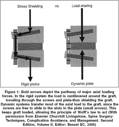
In accordance with Wolff law, some level of compressive forces borne by the bone fusion mass is necessary for fusion and healing to occur (Kowalski et al. 2001). Excessively rigid posterior spinal fixation devices can also lead to stress shielding of the fusion mass (Saphier et al. 2007; Kanayama et al. 2000). Stress shielding refers to a reduction of load and stress seen by bone fusion mass (< ~70% of the total load), as a disproportionately large amount of the total load may be borne by the posterior fixation device (Fig. 3). This occurrence can further be complicated due to low bone-mineral density and osteoporosis (Bhamare et al. 2013; Park et al. 2013).

Load bearing vs. load sharing after fusion surgery. (Source: http://www.bioline.org.br/showimage?ni/photo/ni05146f1.jpg, adapted from “Benzel, E.C., 2005. Spine Surgery: Techniques, Complication Avoidance, and Management”)
Failed bony fusion, or pseudarthrosis, is also an iatrogenic complication, with incidence rates ranging from 5% to 35% in the lumbar spine (Chun et al. 2015). While controversial, it is important to note that according to the United States Food and Drug Administration (FDA) guidelines, greater than 3 mm of translation motion and greater than 5 of angular motion on flexion-extension radiographs should be considered as a failed bony fusion (Gruskay et al. 2014; Chun et al. 2015).
Donor-site morbidity (due to bone grafting for fusion mass) is also a complication reported after spinal fusion (Vaz et al. 2010), which may be addressed by using alternatives such as recombinant human bone morphogenetic proteins (rhBMPs). Prolonged recuperation time also remains a concern (Serhan et al. 2011). Overall, patient satisfaction rate for lumbar spinal fusion averages around 60–70% (Turner et al. 1992; Slosar et al. 2000).
Rationale for Dynamic Stabilization and Device Classification
To address some of the limitations posed by fusion surgery, there has been a growing interest in the field of dynamic spine stabilization (Bhamare et al. 2013). These devices may be viable alternatives addressing a range of spinal disorders, including stenosis and discogenic low back pain (Serhan et al. 2011). The rationale for dynamic stabilization is that by preserving functional range of spinal motion, one can alleviate at least some of the complications related to spinal fusion listed above. It should be noted that up to 5° of angular motion may be present on flexion-extension radiographs in the case of a successful fusion (Gruskay et al. 2014; Chun et al. 2015). Hence, if the ROM allowed under a similar radiographic evaluation for a dynamic stabilization device is less than 5°, justifying the use of the device as a truly non-fusion dynamic stabilization device is controversial. To the best of our knowledge, no pedicle screw-based PDS device has been approved by the FDA for use other than an adjunct to spinal fusion (Fig. 4).

Posterior fixation vs. Dynesys posterior dynamic stabilization device with flexible components. (Sources: SpinalFusion.jpg and https://www.hindawi.com/journals/aorth/2013/753470.fig.0012.jpg, and “What is Spinal fusion?.” Atlantic Brain and Spine, www.brainspinesurgery.com/spinal-fusion/)
While a dynamic stabilization device may not increase the range of motion (ROM) of the segment being treated, the objective is to preserve normal motion as much as possible, while at the same time limiting abnormal motion (Sengupta and Herkowitz 2012). In the case of a PDS device, some loss of ROM (compared to ROM before surgery) may be unavoidable (Sengupta and Herkowitz 2012). Another important consideration for a dynamic stabilization device is to ensure the adequate level of load transfer through the joint. In the case of a PDS device, it has to sustain loads for a longer amount of time, compared to posterior fixation devices used for fusion, since there is no bone fusion mass (Fig. 1). Hence, to avoid fatigue failure and implant loosening, which are often seen in a PDS device (Bhamare et al. 2013), the PDS device should be load-sharing, and not load-bearing (Sengupta and Herkowitz 2012). While there is no fusion mass to share load with (Fig. 3), the PDS device should be able to share load with other load-bearing spinal components. It should be noted that ROM and loading can be interdependent (Grob et al. 2005; Mulholland and Sengupta 2002; Kirkaldy-Willis and Farfan 1982; Doria et al. 2014), and hence, alteration (or restoration) of one may also impact the other.
One way to classify dynamic stabilization devices is by defining whether the device replaces an existing joint or a mobile anatomical region, or whether it augments it. Thus, preservation of motion after surgery can be achieved by either replacing the entire intervertebral disc (disc replacement), just the nucleus (nucleus replacement), or the facet joints (facet replacement). Alternately, preservation of motion after surgery can be achieved by augmenting the posterior spinal elements. The indications for use of each of these devices can be very different. However, from a biomechanical perspective, each device aims to address the instability introduced by surgery by allowing “some” motion at the joint (vs. fusing the joint) and sharing load within the joint.
This chapter will focus on posterior dynamic stabilization: devices that either allow some motion or control motion at a spinal joint, by augmenting the posterior spinal elements, that is, PDS devices, with a focus pedicle screw and interspinous PDS devices used in the lumbar spine.
Posterior Dynamic Stabilization: Methods for Testing and Performance Evaluation
Pedicle-Based PDS Devices: Preclinical In Vitro Mechanical Testing
Static and dynamic reliability testing of PDS devices is based on standards developed by the American Society for Testing and Materials (ASTM) and/or the International Standardization Organization (ISO). For pedicle screw-based PDS devices, the ASTM F1717 and/or ISO 12189 standards are used for assembly level testing (Fig. 5) (La Barbera et al. 2015), wherein the complete instrumentation system is subjected to bending loads and stresses (Bhamare et al. 2013). These standards describe implant assembly with simulated vertebral body test blocks in either a vertebrectomy model (ASTM F1717) or a model with anterior support (ISO12189 – calibrated springs – Fig. 5) (La Barbera and Villa 2017). While the F1717 standard reflects the worst-case load-bearing scenario, the ISO12189 standard reflects a load-sharing scenario (Fig. 3). In the context of PDS devices, an important distinction between the two standards is the ASTM F1717 may not be directly usable, due to the combination of the allowable degree of freedom in the simulated vertebral body test blocks and the allowable motion of PDS device itself.

Testing setups for posterior spinal implants per ASTM F1717 and ISO12189 standards. (Source: https://ars.els-cdn.com/content/image/1-s2.0-S1529943015012024-spinee56502-fig-0001_lrg.jpg)
Component and Interface Level Static and Dynamic Testing
Component and interface (bone-implant as well as inter-component) testing is also performed both statically and dynamically. In the case of pedicle screw-based PDS devices, component level performance is commonly performed for pedicle screw pullout (ASTM F543) and bending loads (ASTM F1798) as well as for flexible rod component bending strength (ASTM F2193).
For both component and interface level testing, dynamic cyclic testing for pedicle screw-based PDS systems is performed to a runout of 10 million cycles. With 125 significant bends performed annually, 10 million cycles represents 80 years of wear (Vermesan et al. 2014; Schwarzenbach et al. 2005). This testing characterizes the asymptotic endurance level for load/stress, that is, the level below which the implant/ component/material does not fail and can be cycled infinitely.
Preclinical In Vitro Biomechanical Testing and Simulation
PDS devices are commonly evaluated for biomechanical performance characterization using cadaveric experiments. The primary modes of loading tested in these experiments are shown in Fig. 6 below.

Primary modes of loading tested in a cadaveric experimental setup. (Source: https://clinicalgate.com/dynamic-stabilization-of-the-lumbar-spine-indications-and-techniques/)
Physiologic loading and range of motion are applied to cadaveric specimens by applying pure moments and a compressive follower load (Patwardhan et al. 1999). Specimens are tested intact, after destabilization surgery, and finally after device implantation under load control or by using a hybrid testing protocol (Goel et al. 2005; Bennett et al. 2015). Testing can also be simulated using finite element (FE) modeling, provided the FE model is validated against experimental results. Figure 7 shows an FE model of the lumbar spine and the corresponding cadaveric experimental setup for testing a dynamic stabilization system.

Finite element modeling of the spine and the corresponding experimental setup. (Source: https://www.ncbi.nlm.nih.gov/pmc/articles/PMC3626386/)
In addition to characterizing range of motion (ROM), biomechanical testing and simulation also allow for quantification of interpedicular travel (IPT) and displacement (Fig. 8), which is particularly useful for design, development and optimization of dynamic stabilization devices (Cook et al. 2012; Yeager et al. 2015). Limiting interpedicular motion in PDS implants may lead to implant loosening over time (Lima et al. 2017). Using these testing and simulation methods, it has been determined that an axial stiffness of 45 N/mm and bending stiffness of 30 N/mm can reduce spinal ROM by 30% (compared to intact specimen ROM), and this is thought to be an optimal level of motion reduction after surgery (Erbulut et al. 2013; Schmidt et al. 2009). When pedicle screw-based PDS have stiffness characteristics that are greater than optimum, there can be a larger reduction in ROM, thereby rendering their performance almost similar to fusion devices .

Interpedicular travel (r3) and displacement measurement for a PDS device during in vitro biomechanical testing. (Sources: http://www.isass.org/pdf/sas10/4-Friday/Abstract_301.pdf and https://www.hindawi.com/journals/aorth/2015/895931/)
Evaluating In Vivo Performance
In addition to ROM measurements from in vivo flexion extension radiographs, IPT measurements can also be characterized in vivo. More recently, translation per degree of rotation (TPDR – Fig. 9) and qualitative stability index (QSI) have been used to characterize instability in vivo (Hipp et al. 2015). A QSI score of 2 indicates a TPDR value 2 standard deviations compared to values observed in healthy controls, and this in turn may indicate instability and poor quality of motion. Similar measurements may also be performed using fluoroscopy (Davis et al. 2015), and these instability measurements can be adapted for evaluating in vivo ROM quality and characterizing in vivo performance of PDS devices. Finally, patient reported outcome measures (PROMs) (Nayak et al. 2015) that quantify quality of life, pain, and disease-specific disability after surgery are critical for evaluating the long-term performance of PDS devices.

Measurement of TPDR (translation per degree of rotation) from radiographs. (Source: https://www.ncbi.nlm.nih.gov/pmc/articles/PMC4528437/)
Pedicle Screw-Based PDS Devices: In Vivo Performance and Failure Modes
Pedicle screw-based PDS devices are based on instrumentation and techniques that surgeons are most familiar with, due to their experience with posterior fixation for spinal fusion (Barrey et al. 2008). These devices are commonly approved for use in spinal fusion, or as an adjunct to fusion, but not as stand-alone devices in the absence of fusion. Despite familiar surgical techniques and extensive preclinical testing, pedicle screw-based PDS devices are still considered investigational for the treatment of disorders of the spine. One of the main reasons is that it is not yet clear from randomized clinical trials (RCTs) whether pedicle screw-based PDS truly offer advantages over conventional spinal fusion, in terms of health outcomes. Other reasons range from some PDS devices not being truly dynamic (in vivo range of motion is similar to fusion) to device failure and screw loosening (Kaner et al. 2010b; Stoffel et al. 2010; Kocak et al. 2010; Grob et al. 2005; Chen et al. 2011).
Below is a summary of some of the pedicle screw-based PDS devices that have been studied in vivo as stand-alone devices, that is, without fusion and bone graft. A discussion of failure modes, where applicable, is also included.
Accuflex System (Globus Medical Inc.)
The Accuflex system (Fig. 10) consists of a flexible rod anchored by pedicle screws made of titanium alloy. Flexibility in the rod is achieved by helical cuts along the length of the rod. The flexible rod system has undergone extensive in vitro static and dynamic biomechanical testing (Reyes-Sánchez et al. 2010). In a 20-patient study with 2-year follow-up, improvements in all clinical measurements and PROMs were observed (Reyes-Sánchez et al. 2010). However, hardware fatigue failure was also observed in ~22% of the subjects. Failure included rod breakage as well as pedicle screw breakage in the bone. Both these failure mechanisms were caused due a combination of a large bending moment and stress concentration in the failure regions .

Accuflex system with a flexible rod. (Source: https://www.ncbi.nlm.nih.gov/pmc/articles/PMC4365627/)
BioFlex System (Bio-Spine)
The BioFlex system (Fig. 11) consists of a flexible spring made out of Nitinol (a shape memory alloy) anchored by pedicle screws made out of titanium alloy. In a 12-patient study with 2-year follow-up, reduced ROM was observed at the treated level (compared to ROM before surgery), with minimal changes at adjacent levels (Zhang et al. 2009). In another study with short-term follow-up (less than 1 year), 28 patients treated solely with the BioFlex (Kim et al. 2007), a similar reduced ROM was observed at the treated level. Limited long-term data is available for this device. It should also be noted that Nitinol is a notch-sensitive material which can reduce fatigue strength (Yoshihara 2013). Notch sensitivity describes the sensitivity of a material to geometric discontinuities and can have a significant negative effect on fatigue strength.

BioFlex system with flexible springs. (Source: https://pubmed.ncbi.nlm.nih.gov/20401848/)
CD Horizon Agile (Medtronic Sofamor Danek)
In the CD Horizon Agile system (Fig. 12), the rod component between the pedicle screws is available in different sizes to offer a less stiff (longer spacer) or a more stiff (shorter spacer) option for dynamic stabilization. The spacer, made out of a thermoplastic polymer (polycarbonate urethane or PCU), encloses a titanium alloy cable. While allowing a greater ROM that most other PDS devices, the implant was noted to break due to shear-related failure of the cable component, particularly in cases of advanced instability (Doria et al. 2014). Shear-related failure occurred due to kinking of the cable component during anterior-posterior translation of the spinal segment (Hoff et al. 2012).

CD Horizon Agile . (Source https://pubmed.ncbi.nlm.nih.gov/20401848/)
Cosmic Posterior Dynamic System (Ulrich Medical)
The Cosmic posterior dynamic system (Fig. 13) includes a hinged pedicle screw which can reduce stresses at the bone screw interface while allowing segmental motion (Gomleksiz et al. 2012). The pedicle screw (threads) includes a calcium phosphate coating to promote osteointegration. The rod in this system is rigid. In a study with 30 patients and over 3 years of follow-up (Kaner et al. 2010a), significant improvement in PROMs were observed, and no screw breakage was observed. One instance of screw loosening was reported.

Cosmic PDS with a hinged pedicle screw. (Source: https://pubmed.ncbi.nlm.nih.gov/20401848/)
Dynesys (Zimmer Biomet)
Dynesys (Fig. 4, right) has the largest amount of clinical follow-up data, compared to other pedicle screw-based PDS. Between the pedicle screws, the system consists of a thermoplastic spacer (PCU) that encloses a cord (made out of polyethylene terephthalate or PET). A comprehensive literature review (Pham et al. 2016) spanning 21 studies and a total of 1166 patients with mean follow-up of almost 3 years has shown that the pedicle screw loosening rate is ~12% (higher than the rate commonly observed after fusion) and ASD rate is ~7%, (slightly lower than the rate commonly observed after fusion). The pedicle screw fracture rate for Dynesys was less than 2%. In another study with 46 patients and mean follow-up of over 4 years (Zhang et al. 2016), significant improvements in PROMs were observed for patients treated with Dynesys, as well as for patients treated with fusion. While the mean ROM (flexion-extension radiographs) was lower than 5° for both groups (patients treated with Dynesys or fusion), the Dynesys system did allow slight greater ROM and lower ASD rate, compared to patients treated with fusion.
Graf Ligament (SEM Co.)
The Graf ligament (Fig. 14) represents the earliest attempts in using a flexible PDS. The device includes a braided polyester (polypropylene) tension band between titanium pedicle screws.

Graf ligament inserted between pedicle screws. (Source: https://www.ncbi.nlm.nih.gov/pmc/articles/PMC4365627/)
The hypothesis for this device was that abnormal rotational motion was responsible for pain generation, and this device was designed to control the same by locking the lumbar facets in an extended position (Doria et al. 2014; Erbulut et al. 2013). The Graf ligament transfers load from the anterior disc to the posterior annulus, increasing disc pressure, which can accelerate disc degeneration (Gomleksiz et al. 2012) and even cause lateral recess stenosis. In a review of 43 patients with a minimum of 8 years follow-up (Choi et al. 2009), angular instability was observed in 28% of the segments, while translational instability was observed in 5% of the segments. Additionally, adjacent segment instability was observed in 42% and 30% of the subjects at the upper and lower segments, respectively. No instrumentation failures were reported. In another study with 31 patients and 7-year follow-up, significant improvements in PROMs have been reported, despite an established degenerative process (Gardner and Pande 2002).
Isobar TTL (Scient’x)
The Isobar TTL system (Fig. 15) is composed of a semirigid titanium alloy rod with a dampener stacked with titanium alloy rings. This rod is inserted between titanium alloy pedicle screws and the system allows some axial and angular motion. In a review of 37 patients with a mean follow-up of 2 years, excellent improvement PROMs have been reported (Li et al. 2013). However, ROM after surgery was significantly lower (compared to ROM before surgery) and new signs of degeneration were observed at adjacent levels in 39% of the patients, with 8% of the patients requiring revision due to ASD.

Isobar semi-rigid rod. (Source https://www.ncbi.nlm.nih.gov/pmc/articles/PMC4365627/)
NFlex (Synthes Spine)
In the NFlex device (Fig. 16), a polyaxial titanium alloy pedicle screw is affixed to a central titanium core which is integrated with a PCU spacer. This design allows for a physiologic change in interpedicular distance (Fig. 8). In a study reporting 2-year clinical outcomes in 65 patients (Coe et al. 2012), 25 patients received non-fusion dynamic stabilization solely with Isobar TTL . Significant improvements in PROMs were observed in these patients, with one instance each of rod fracture and pedicle screw loosening.

NFlex device in neutral, flexion and extension positions. (Source: https://www.ncbi.nlm.nih.gov/pmc/articles/PMC3424174/)
Stabilimax NZ (Rachiotek LLC)
The Stabilimax NZ device (Fig. 17) aims to provide maximum support in the neutral zone (NZ – the initial portion of the total range of motion, where minimal resistance to motion is offered by passive spinal structures) while maintaining maximum possible total range of motion (reduced support in the final portion of total range of motion, where maximal resistance to motion is offered by active and passive spinal structures) (Panjabi and Timm 2007). This is achieved through the use of dual concentric springs that permit physiologic interpedicular travel and the use of ball and socket joints to reduce bending moment at the bone screw interface and permitting axial rotation. In a preliminary report on 60 patients with 2-year follow-up (Neel Anand et al. 2012), significant improvements in PROMs were observed. IPT travel (Fig. 8) was also physiologic. However, pedicle screw breakage was also seen in 10% of the cases. Grit blasted surface of the pedicle screws was found to be the root cause of failure (grit blasting of titanium alloy screws can promote osteointegration, but it can also make the surface notch sensitive, thereby reducing fatigue life). The surface treatment was later changed using laser shock peening (LSP). LSP improves fatigue life by impacting residual stresses (Bhamare et al. 2013).

Stabilimax NZ device dual springs and ball-socket joints. (Source: https://www.ncbi.nlm.nih.gov/pmc/articles/PMC4365627/)
Percudyn (Interventional Spine)
In the Percudyn device (Fig. 18), a PCU stabilizer is installed onto an anchor. This is a pedicle screw-based device without an interpedicular connection. Biomechanically, the Percudyn device serves to augment the posterior elements of the functional facet by serving as a mechanical stop between the inferior and superior articular facets (Smith et al. 2011). In a study reporting on 96 patients at a 2-year follow-up period (Canero and Carbone 2015), significant improvements were observed in PROMs, with more than 70% of the patients satisfied with the procedure, while 10% of the patients required revision surgery at longer follow-up.

Percudyn PCU spacer inserted onto the anchor. (Source: https://www.ncbi.nlm.nih.gov/pmc/articles/PMC4365627/)
Interspinous Devices: Preclinical In Vitro Mechanical Testing
The motion preserving interspinous devices could be divided into devices that oppose motion in a rigid manner and devices that oppose it in a flexible manner. Rigid, or static, devices consist of relatively noncompressible solid materials like titanium or PEEK; their main function is to ensure a consistent level of posterior distraction during extension. The flexible interspinous devices allow for compression during extension and could be classified as flexible/dynamic devices. They offer a higher level of elasticity that allows their deformation during extension. This is achieved by the material and/or their shape.
Parchi et al. 2014 have characterized the biomechanical effects of interspinous devices by:
-
1.
Modifying/Stabilizing the motion segment and altering the range of motion (ROM)
-
2.
Decompression of the spinal canal and foramina via posterior distraction
-
3.
Reduction of intradiscal pressure and facet load
-
4.
Impact on sagittal alignment and instantaneous axis of rotation (IAR) of the treated segment
Human cadaveric studies to investigate the range of motion, instantaneous access or rotation, or measuring the intradiscal pressures of intact condition and post-decompression and/or interspinous device insertion are commonly used to evaluate the in vitro performance of these devices. Several biomechanical studies on interspinous device are reported in literature (Lindsey et al. 2003, Phillips et al. 2006, Tsai et al. 2006, Lafage et al. 2007). In cadaveric studies, interspinous devices improve the stability of the treated motion segment in flexion-extension but do not stabilize the spine in axial rotation or lateral bending. Zheng et al. (2010) found also that size of the interspinous device affect their performance, smaller interspinous device did not provide the stabilization of larger devices. He found that using a spacer with height equal to the distance of the interspinous process was associated with a slight flexion of the segment and less effects on the dimension of the spinal canal and foramen. An oversized device, on the other hand, could induce a kyphotic position and may increase disc loading. Selecting the appropriate device design, size, and material while taking in consideration the treatment goal, patients’ pathology, bone quality, and symptoms should be carefully considered to achieve the best biomechanical and clinical outcome.
Posterior Dynamic Interspinous Devices: In Vivo Performance and Failure Modes
The interspinous devices were designed as an alternative treatment for neurogenic claudication and pain which is attributed to facet joint disease. The spine is kept in a flexed position by which the interspinous devices increase the total canal and foraminal size, which decompresses the cauda equina, which is responsible for neurogenic claudication. This device allows for neural decompression with minimal tissue resection; thus, the device is less invasive and can be implanted without a laminectomy. It avoids the risk of epidural scaring and cerebrospinal fluid leakage by functioning through indirect decompression. In some cases, interspinous dynamic stabilization is used to prevent the instability that occurs after decompression.
These devices limit extension of the spine, allow for the unloading of the facet joint, and allow for the relief of pain attributed to facet disease as well (Khoueir et al. 2007). The notion of interspinous device to produce segmental posterior distraction was first introduced in the 1960s by Dr. Fred Knowles. He is better known for his hip pin design; however, he reported limited success with the spinal device due to subsidence and displacement. His ideas were latter improved upon, in the form of the Xstop device (Kyphon, Sunnyvale, California). There have been multiple interspinous devices which have been developed, such as the X-stop, DIAM, Wallis system, and the CoFlex system. All these devices work to limit spinal extension. The interspinous spacers may be helpful when more conservative (nonoperative) care does not improve symptoms. All of these devices allow the spine to be held in a position of slight flexion, in order to decompress the spinal cord or nerve roots. The spine, however, may still rotate axially or bend laterally when the device is in place.
The Wallis System (Zimmer)
The Wallis system was the first interspinous device introduced in Europe around 1986 and was developed by Sénégas (Fig. 19). The design originated with a titanium block inserted between adjacent processes, which is then held in place with a flat Dacron cord or ribbon wrapped around the spinous process above and below the block. This first-generation device provided positive results and so the second generation of Wallis implants was developed. The main change was seen in the material used for the interspinous block, which was changed to PEEK, which is a plastic like polymer that has more flexibility than titanium. The design and material allow for the minimization of the need for bone resection. In a controlled study which was done between 1998 and 1993, more than 300 patients were treated for degenerative lesions, in which positive results were found. Trials of the first-generation implant provided evidence that the interspinous system of nonrigid stabilization is effective against lower back pain caused by degenerative instability (Anderson et al. 2006). More recently Song et al. (2019)) provided information on 33 patients treated for degenerative lumbar spine diseases with the Wallis system. ROM of surgical segments was significantly lower than those before operation (P < 0.05), while ROM of the upper and lower adjacent segments and disc height did not change significantly (P > 0.05).

Wallis® posterior dynamic stabilization system (https://www.ncbi.nlm.nih.gov/pmc/articles/PMC4365627/)
X-STOP (Medtronic)
The X-stop is made of titanium and PEEK components, with side wings encapsulating the lateral sides of the spinous processes to reduce the risk of implant migration (Fig. 20). FDA approval was obtained in 2005 after a 2-year clinical study. The device is approved for use in patients aged 50 years or older with lower-extremity neurogenic pain from lumbar spinal stenosis and can be implanted under local anesthesia. In the pilot study, inclusion criteria were mild or moderate symptoms that were relieved by flexion and the ability to walk at least 50 ft. Exclusion criteria were a fixed motor deficit or prior treatment with X-stop (Anderson et al. 2006).

X-Stop device interspinous spacer Medtronic (https://www.ncbi.nlm.nih.gov/pmc/articles/PMC4365627/)
DIAM (Medtronic)
The Device for Intervertebral Assisted Motion (DIAM) is made of a silicon H-shaped spacer encased within a Polyethylene terephthalate (Polyester) jacket that is secured (after removal of the interspinous ligament) with two associated tethers, around the supra-adjacent and sub-adjacent spinous processes (Fig. 21). In the past, DIAM has been successful in long-term treatment of lower back pain caused by degenerative disc disease. The first clinical case was performed in 1997 in France, and 25,000 patients have been treated outside the United States since then. In 2010 study, Buric et al. found that over two-thirds of patients achieved and maintained significant, clinically apparent differences in both VAS scores and Roland-Morris Disability Questionnaire (RMDQ) scores over a 48-month period (Buric and Pulidori 2011). FDA randomized clinical trials to evaluate the effectiveness of DIAM versus decompression versus posterolateral fusion were completed in December 2010. However, in 2016 the FDA’s Orthopedic and Rehabilitation Devices Panel of the Medical Devices Advisory Committee recommended against approval for the DIAM spinal stabilization system.

Device for intervertebral assisted motion (DIAM) (https://www.ncbi.nlm.nih.gov/pmc/articles/PMC4365627/)
Recent study by Krappel et al. (2017) reported on a multicenter prospective randomized clinical study of 146 patients with a single level disc herniation (L2 to L5): 75 investigational (herniectomy and DIAM) and 71 control (herniectomy alone) treated and followed up for 24 months. Leg pain, back pain, and the level of disability were not significantly different between groups; however, the number of patients reaching the minimum clinically important difference (MCID) improvement for back pain was significantly higher in the investigational group at 6 through 24 months.
Coflex Interlaminar Stabilization Device (RTI Surgical)
The CoFlex is based on the interspinous-U design from Fixano (Péronnas, France) that was clinically used from 1995 onward (Fig. 22). It is made in its classic form as a titanium U-shaped metal design that is maintained between spinous processes with side wings, so as to control movement while allowing motion, being marketed as a non-fusion device. In 2012 the FDA approved the Coflex device after an IDE study.

Coflex® interlaminar stabilization (https://www.ncbi.nlm.nih.gov/pmc/articles/PMC4365627/)
Schmidt et al. (2018) performed a prospective, randomized, multicenter study with 2-year follow-up to compare the performance of decompression with and without Coflex interlaminar stabilization. This study reports a multicenter, randomized controlled trial in which decompression with interlaminar stabilization (D + ILS) was compared with decompression alone decompression alone (DA) for treatment of moderate to severe lumbar spinal stenosis. 230 patients (1:1 ratio) randomized to either DA or D + ILS (Coflex) were treated at seven sites in Germany. There was no significant difference in the individual patient-reported outcomes (e.g., ODI, VAS, ZCQ) between the treatments. However, microsurgical D + ILS increases walking distance, decreases compensatory pain management, and maintains radiographic foraminal height, extending the durability and sustainability of a decompression procedure. To date, Coflex has been implanted in more than 163,000 patients in over 60 countries worldwide.
In recent years multiple companies have offered various devices, such as NuVasive with ExtendSure; Biomech’s (Taipei, Taiwan) Promise and Rocker designs, made of PEEK and mobile core and articulated design, respectively; Cousin Biotech (Wervicq-Sud, France) with Biolig silicon encapsulated in woven synthetics; Alphatec (Carlsbad, California) with the HeliFix screwtype PEEK space design; Vertiflex (San Clemente, California) with the Superion implant whose deployable wings aim at less invasive insertion (FDA cleared after completing PMA clinical studies in 2016); Orthofix (Bussolengo, Italy) with InSWing; Pioneer with BacJac; Maxx Spine (Bad Schwalbach, Germany) with I-MAXX; Sintea Plustek (Assago, Italy) with Viking; Globus Medical with Flexus; and Privelop (Neunkirchen-Seelscheid, Germany) (Serhan et al. 2011) (Fig. 23).

Other interspinous spacer alternatives: (a) Promise; (b) Rocker; (c) Biolig; (d) HeliFix; (e) Superion; (f) InSpace; (g) Aperius; (h) InSWing; (i) BacJac; (j) I-MAXX; (k) Viking; (l) Flexus; (m) Spinos; and (n) Wellex (Eden Spine) source (https://www.ncbi.nlm.nih.gov/pmc/articles/PMC4365627/)
Discussion
Traditional fusion continues to be the gold standard for treating degenerative spinal disorders. Dynamic spinal stabilization is based on the concept of restricting movement of spinal segments rather than preventing the movement, that is, it restricts movements in the directions that may cause pain or instability, but permits motion in other directions. Dynamic spinal stabilization can achieve spinal stability and prevent diseases of adjacent segments without requiring fusion. Clinical indications for the use of PDS devices are still very broad and lack sufficient evidence. Scientific reviews have indicated that use of PDS pedicle-based systems as an adjunct to fusion may be acceptable. In fact, a majority of the devices described above as well as other devices (Transition: Globus Medical, and CD Horizon Legacy PEEK rod: Medtronic Sofamor Danek, to name a few) are successfully used as an adjunct to fusion across one or multiple spinal levels. However, fatigue failure is a concern when pedicle screw-based PDS systems are used as stand-alone stabilization devices. Failures have been reported at both the implant component interfaces as well as the bone implant interface. In terms of patient reported scores, PDS systems have produced clinical outcomes comparable to that of fusion, and the incidence of ASD is lower when compared to fusion, at least during short-term follow-up. RCTs with long-term follow-up are required to confirm whether the incidence of symptomatic ASD (and not just radiographic ASD) continues to stay lower when compared to fusion, as well as to prove the safety and efficacy of PDS devices. In summary, improvements in in vitro testing modalities, fatigue behavior, long-term follow-up, and a clear definition of clinical indications for using PDS as stand-alone stabilization devices are required to verify the benefits of this technology.
Similar to pedicle-based dynamic stabilization, interspinous devices are indicated to treat skeletally mature patients suffering from pain, numbness, and/or cramping in the legs (neurogenic intermittent claudication) secondary to a diagnosis of moderate degenerative lumbar spinal stenosis, with or without grade 1 spondylolisthesis, confirmed by x-ray, MRI, and/or CT evidence of thickened ligamentum flavum, narrowed lateral recess, and/or central canal or foraminal narrowing. Interspinous devices are also indicated for patients with impaired physical function who experience relief in flexion from symptoms of leg/buttock/groin pain, numbness, and/or cramping, with or without back pain, and who have undergone at least 6 months of nonoperative treatment. Interspinous devices may be implanted at one or two adjacent lumbar levels in patients in whom treatment is indicated at no more than two levels, from L1 to L5 (Khoueir et al. 2007; Senegas 2002).
Interspinous dynamic stabilization has theoretical advantages over conventional fusion, as it maintains stability by restricting mobility, whereas fusion simply prevents motion. Relatively good clinical results have been reported in the literature. However, despite the increasing use of this technology, few long-term review studies have been conducted to assess its safety and efficacy. Interspinous dynamic stabilization produced slightly better clinical outcomes than conservative treatments for spinal stenosis. The complication rate of interspinous dynamic stabilization has been reported to be 0–32.3% in 3- to 41-month follow-up studies. The complication rate of combined interspinous dynamic stabilization and decompression treatment (32.3%) was greater than that of decompression alone (6.5%), but no complication that significantly affected treatment results was found (Anderson et al. 2006; Zucherman et al. 2005). The typical complications of interspinous devices include spinous process fracture, especially with stiff design; novel radiculopathy, especially with devices with limited motion-constraining ability; and returning or increased pain around the implant area. Implant dislodgement is also a potential complication, particularly in those designs with limited fixation means. Compared to stiff and rigid interspinous designs, dynamic designs such as the Wallis or Coflex have relatively lower device complications.
References
Agarwal R et al (2009) Osteoinductive bone graft substitutes for lumbar fusion: a systematic review. J Neurosurg Spine 11(6):729–740
Anderson PA, Tribus CB, Kitchel SH (2006) Treatment of neurogenic claudication by interspinous decompression: application of the X STOP device in patients with lumbar degenerative spondylolisthesis. J Neurosurg Spine 4(6):463–471. https://doi.org/10.3171/spi.2006.4.6.463
Bakar D et al (2016) Decompression surgery for spinal metastases: a systematic review. Neurosurg Focus 41(2):E2
Barrey CY et al (2008) Biomechanical evaluation of pedicle screw-based dynamic stabilization devices for the lumbar spine: a systematic review. SAS J 2(4):159–170
Bellato RT et al (2015) Late failure of posterior fixation without bone fusion for vertebral metastases. Acta Ortopédica Brasileira 23(6):303–306
Bennett CR, DiAngelo DJ, Kelly BP (2015) Biomechanical comparison of robotically applied pure moment, ideal follower load, and novel trunk weight loading protocols on L4-L5 cadaveric segments during flexion-extension. Int J Spine Surg 9:33
Benzel EC (2001a) Spinal fusion. In: Biomechanics of spine stabilization. American Association of Neurological Surgeons, Rolling Meadows, pp 121–133
Benzel EC (2001b) The destabilizing effects of spinal surgery. In: Biomechanics of spine stabilization. American Association of Neurological Surgeons, Rolling Meadows, pp 111–120
Benzel EC (2001c) Trauma, tumor and infection. In: Biomechanics of spine stabilization. American Association of Neurological Surgeons, Rolling Meadows, pp 61–82
Bhamare S et al (2013) Design of dynamic and fatiguestrength-enhanced orthopedic implants. In: Multiscale simulations and mechanics of biological materials. Wiley, Oxford, UK, pp 333–350
Buric J, Pulidori M (2011) Long-term reduction in pain and disability after surgery with the interspinous device for intervertebral assisted motion (DIAM) spinal stabilization system in patients with low back pain: 4-year follow-up from a longitudinal prospective case series. Eur Spine J 20(8):1304–1311
Canero G, Carbone S (2015) The results of a consecutive series of dynamic posterior stabilizations using the PercuDyn device. Eur Spine J 24(S7):865–871
Chen H et al (2011) Influence of 2 different dynamic stabilization systems on sagittal spinopelvic alignment. J Spinal Disord Tech 24(1):37–43
Choi Y, Kim K, So K (2009) Adjacent segment instability after treatment with a Graf ligament at minimum 8 years’ followup. Clin Orthop Relat Res 467(7):1740–1746
Chun DS, Baker KC, Hsu WK (2015) Lumbar pseudarthrosis: a review of current diagnosis and treatment. Neurosurg Focus 39(4):E10
Coe JD et al (2012) NFlex dynamic stabilization system: two-year clinical outcomes of multi-center study. J Korean Neurosurg Soc 51(6):343–349
Cook DJ, Yeager MS, Cheng BC (2012) Interpedicular travel in the evaluation of spinal implants. Spine 37(11):923–931
Davis R et al (2015) Measurement performance of a computer assisted vertebral motion analysis system. Int J Spine Surg 9:1–13
Doria C, Muresu F, Leali PT (2014) Dynamic stabilization of the lumbar spine: current status of minimally invasive and open treatments. In: Minimally invasive surgery of the lumbar spine. Springer, London, pp 209–227
Egger EL et al (1993) Effects of axial dynamization on bone healing. J Trauma 34(2):185–192
Erbulut DU et al (2013) Biomechanics of posterior dynamic stabilization systems. Adv Orthop 2013:451956
Gardner A, Pande KC (2002) Graf ligamentoplasty: a 7 year follow-up. Eur Spine J 11(Suppl 2):S157–S163
Goel VK et al (2005) Effects of charité artificial disc on the implanted and adjacent spinal segments mechanics using a hybrid testing protocol. Spine 30(24):2755–2764
Gomleksiz C et al (2012) A short history of posterior dynamic stabilization. Adv Orthop 2012:629698
Grob D et al (2005) Clinical experience with the Dynesys semirigid fixation system for the lumbar spine: surgical and patient-oriented outcome in 50 cases after an average of 2 years. Spine 30(3):324–331
Gruskay JA, Webb ML, Grauer JN (2014) Methods of evaluating lumbar and cervical fusion. Spine J 14(3):531–539
Hasegawa K et al (2013) Biomechanical evaluation of destabilization following minimally invasive decompression for lumbar spinal canal stenosis. J Neurosurg Spine 18(5):504–510
Hipp JA et al (2015) Development of a novel radiographic measure of lumbar instability and validation using the facet fluid sign. Int J Spine Surg 9:37
Hoff E et al (2012) Which radiographic parameters are linked to failure of a dynamic spinal implant? Clin Orthop Relat Res 470(7):1834–1846
Kanayama M et al (2000) In vitro biomechanical investigation of the stability and stress-shielding effect of lumbar interbody fusion devices. J Neurosurg 93(2 Suppl):259–265
Kaner T, Sasani M et al (2010a) Clinical outcomes of degenerative lumbar spinal stenosis treated with lumbar decompression and the cosmic “semi-rigid” posterior system. SAS J 4(4):99–106
Kaner T, Dalbayrak S, Oktenoglu T, Sasani M, Aydin AL, Ozer AF (2010b) Comparison of posterior dynamic and posterior rigid transpedicular stabilization with fusion to treat degenerative spondylolisthesis. Orthopedics 33(5). Published 2010 May 12. https://doi.org/10.3928/01477447-20100329-09
Khoueir P, Kim KA, Wang MY (2007) Classification of posterior dynamic stabilization devices. Neurosurg Focus 22(1):E3
Kim Y-S et al (2007) Nitinol spring rod dynamic stabilization system and Nitinol memory loops in surgical treatment for lumbar disc disorders: short-term follow up. Neurosurg Focus 22(1):E10
Kirkaldy-Willis WH, Farfan HF (1982) Instability of the lumbar spine. Clin Orthop Relat Res 165:110–123
Kocak T et al (2010) Screw loosening after posterior dynamic stabilization – review of the literature. Acta Chir Orthop Traumatol Cechoslov 77(2):134–139
Kowalski RJ, Ferrara LA, Benzel EC (2001) Biomechanics of bone fusion. Neurosurg Focus 10(4):E2
Krappel F, Brayda-Bruno M, Alessi G, Remacle JM, Lopez LA, Fernández JJ, Maestretti G, Pfirrmann CWA (2017) Herniectomy versus Herniectomy with the Diam spinal stabilization system in patients with sciatica and concomitant low back pain: results of a prospective randomized controlled multicenter trial. Eur Spine J 26(3):865–876. https://doi.org/10.1007/s00586-016-4796-6. Epub 2016 Oct 4
La Barbera L, Villa T (2017) Toward the definition of a new worst-case paradigm for the preclinical evaluation of posterior spine stabilization devices. Proc Inst Mech Eng H J Eng Med 231(2):176–185
La Barbera L, Ottardi C, Villa T (2015) Comparative analysis of international standards for the fatigue testing of posterior spinal fixation systems: the importance of preload in ISO 12189. Spine J 15(10):2290–2296
Lafage V, Gangnet N, Sénégas J et al (2007) New interspinous implant evaluation using an in vitro biomechanical study combined with a finite-element analysis. Spine (Phila Pa 1976) 32:1706–1713
Lee CK, Langrana NA (1984) Lumbosacral spinal fusion. A biomechanical study. Spine 9(6):574–581
Li Z et al (2013) Two-year follow-up results of the isobar TTL semi-rigid rod system for the treatment of lumbar degenerative disease. J Clin Neurosci 20(3):394–399
Lima LVPC et al (2017) Limiting interpedicular screw displacement increases shear forces in screws: a finite element study. Orthop Traumatol Surg Res 103(5):721–726
Lindsey DP, Swanson KE, Fuchs P, Hsu KY, Zucherman JF, Yerby SA (2003) The effects of an interspinous implant on the kinematics of the instrumented and adjacent levels in the lumbar spine. Spine 28(19):2192–2197
Lindsey DP et al (2015) Sacroiliac joint fusion minimally affects adjacent lumbar segment motion: a finite element study. Int J Spine Surg 9:64
Mulholland RC, Sengupta DK (2002) Rationale, principles and experimental evaluation of the concept of soft stabilization. Eur Spine J 11(Suppl 2):S198–S205
Nayak NR et al (2015) Tracking patient-reported outcomes in spinal disorders. Surg Neurol Int 6(Suppl 19):S490–S499
Neel Anand M, et al (2012) 24 Month functional outcomes from the US IDE Trial Evaluating The Stabilimax®, A lumbar Posterior Dynamic Stabilization (PDS) system with Interpedicular Travel (IPT). In: Meeting of the Lumbar Spine Research Society
Panjabi MM, Timm JP (2007) Development of stabilimax NZ from biomechanical principles. SAS J 1(1):2–7
Parchi PD, Evangelisti G, Vertuccio A, Piolanti N, Andreani L, Cervi V, Giannetti C, Calvosa G, Lisanti M (2014) Biomechanics of interspinous devices. Biomed Res Int 2014:839325
Park Y-S et al (2013) The effect of zoledronic acid on the volume of the fusion-mass in lumbar spinal fusion. Clin Orthop Surg 5(4):292–297
Patwardhan AG et al (1999) A follower load increases the load-carrying capacity of the lumbar spine in compression. Spine 24(10):1003–1009
Pham MH et al (2016) Complications associated with the Dynesys dynamic stabilization system: a comprehensive review of the literature. Neurosurg Focus 40(1):1–8
Phillips FM, Voronov LI, Gaitanis IN, Carandang G, Havey RM, Patwardhan AG (2006) Biomechanics of posterior dynamic stabilizing device (DIAM) after facetectomy and discectomy. Spine J 6(6):714–722
Puttlitz CM et al (2000) Pathomechanisms of failures of the odontoid. Spine 25(22):2868–2876
Rajaee SS et al (2012) Spinal fusion in the United States. Spine 37(1):67–76
Reyes-Sánchez A et al (2010) Posterior dynamic stabilization of the lumbar spine with the Accuflex rod system as a stand-alone device: experience in 20 patients with 2-year follow-up. Eur Spine J 19(12):2164–2170
Saavedra-Pozo FM, Deusdara RAM, Benzel EC (2014) Adjacent segment disease perspective and review of the literature. Ochsner J 14(1):78–83
Saphier PS et al (2007) Stress-shielding compared with load-sharing anterior cervical plate fixation: a clinical and radiographic prospective analysis of 50 patients. J Neurosurg Spine 6(5):391–397
Schlenk RP, Stewart T, Benzel EC (2003) The biomechanics of iatrogenic spinal destabilization and implant failure. Neurosurg Focus 15(3):E2
Schmidt H, Heuer F, Wilke H-J (2009) Which axial and bending stiffnesses of posterior implants are required to design a flexible lumbar stabilization system? J Biomech 42(1):48–54
Schmidt S, Franke J, Rauschmann M, Adelt D, Bonsanto MM, Sola S (2018) Prospective, randomized, multicenter study with 2-year follow-up to compare the performance of decompression with and without interlaminar stabilization. J Neurosurg Spine 28(4):406–415. https://doi.org/10.3171/2017.11.SPINE17643. Epub 2018 Jan 26
Schwarzenbach O et al (2005) Posterior dynamic stabilization systems: DYNESYS. Orthop Clin N Am 36(3 Spec Iss):363–372
Senegas J (2002) Mechanical supplementation by nonrigid fixation in degenerative intervertebral lumbar segments: the Wallis system. Eur Spine J 11(Suppl 2):S164–S169
Sengupta DK, Herkowitz HN (2012) Pedicle screw-based posterior dynamic stabilization: literature review. Adv Orthop 2012(424268):1–7
Serhan H, Mhatre D, Defossez H, Bono CM (2011) Motion-preserving technologies for degenerative lumbar spine: the past, present, and future horizons. SAS J 5(3):75–89. https://doi.org/10.1016/j.esas.2011.05.001. Published 2011 Sep 1
Shono Y et al (1998) Stability of posterior spinal instrumentation and its effects on adjacent motion segments in the lumbosacral spine. Spine 23(14):1550–1558
Slosar PJ et al (2000) Patient satisfaction after circumferential lumbar fusion. Spine 25(6):722–726
Smith ZA et al (2011) A minimally invasive technique for percutaneous lumbar facet augmentation: technical description of a novel device. Surg Neurol Int 2:165
Song KP, Zhang B, Ma JL, Wang B, Chen B (2019) Midterm follow-up efficacy of interspinous dynamic stabilization system for lumbar degenerative diseases. Zhongguo Gu Shang 32(11):991–996. https://doi.org/10.3969/j.issn.1003-0034.2019.11.004
Stoffel M et al (2010) Pedicle screw-based dynamic stabilization of the thoracolumbar spine with the cosmic®-system: a prospective observation. Acta Neurochir 152(5):835–843
Tsai K, Murakami H, Lowery GL, Hutton WC (2006) A biomechanical evaluation of an interspinous device (Coflex) used to stabilize the lumbar spine. J Surg Orthop Adv 15(3):167–172
Turner JA et al (1992) Surgery for lumbar spinal stenosis. Attempted meta-analysis of the literature. Spine 17(1):1–8
Vadapalli S, Sairyo K, Goel VK et al (2006) Biomechanical rationale for using polyetheretherketone (PEEK) spacers for lumbar interbody fusion-a finite element study. Spine (Phila Pa 1976) 31(26):E992–E998. https://doi.org/10.1097/01.brs.0000250177.84168.ba. [published correction appears in Spine. 2007 Mar 15;32(6):710]
Vaz K et al (2010) Bone grafting options for lumbar spine surgery: a review examining clinical efficacy and complications. SAS J 4(3):75–86
Vermesan D et al (2014) A new device used in the restoration of kinematics after total facet arthroplasty. Med Devices (Auckland, NZ) 7:157–163
Virk SS et al (2014) Adjacent segment disease. Orthopedics 37(8):547–555
Weiss LE et al (1997) Pseudarthrosis after postoperative wound infection in the lumbar spine. J Spinal Disord 10(6):482–487
Yeager MS, Cook DJ, Cheng BC (2015) In vitro comparison of Dynesys, PEEK, and titanium constructs in the lumbar spine. Adv Orthop 2015:1–8
Yoshihara H (2013) Rods in spinal surgery: a review of the literature. Spine J 13(10):1350–1358
Zhang HY, Park JY, Cho BY (2009) The BioFlex system as a dynamic stabilization device: does it preserve lumbar motion? J Korean Neurosurg Soc 46(5):431–436
Zhang Y et al (2016) Comparison of the Dynesys dynamic stabilization system and posterior lumbar interbody fusion for lumbar degenerative disease. PLoS One 11(1):e0148071
Zheng S, Yao Q, Cheng L et al (2010) The effects of a new shape- memory alloy interspinous process device on the distribution of intervertebral disc pressures in vitro. J Biomed Res 24(2):115–123
Zucherman JF, Hsu KY, Hartjen CA et al (2005) A multicenter, prospective, randomized trial evaluating the X STOP interspinous process decompression system for the treatment of neurogenic intermittent claudication: two-year follow-up results. Spine (Phila Pa 1976) 30(12):1351–1358
Author information
Authors and Affiliations
Corresponding author
Editor information
Editors and Affiliations
Section Editor information
Rights and permissions
Copyright information
© 2021 Springer Nature Switzerland AG
About this entry

Cite this entry
Khandha, A., Serhan, J., Goel, V.K. (2021). Design Rationale for Posterior Dynamic Stabilization Relevant for Spine Surgery. In: Cheng, B.C. (eds) Handbook of Spine Technology. Springer, Cham. https://doi.org/10.1007/978-3-319-44424-6_24
Download citation
DOI: https://doi.org/10.1007/978-3-319-44424-6_24
Published:
Publisher Name: Springer, Cham
Print ISBN: 978-3-319-44423-9
Online ISBN: 978-3-319-44424-6
eBook Packages: Biomedical and Life SciencesReference Module Biomedical and Life Sciences