
Abstract
Stroke is a major health issue worldwide—one with serious financial and public health implications. As a result, ongoing clinical research on novel and improved stroke therapies is not only pertinent but also paramount. Due to the complexity of a stroke-like event and its many sequelae, devising usable methods and experimental models are necessary to study and better understand the pathophysiological processes that ensue. As it stands, animal models that simulate stroke-like events have proven to be the most logical and effective options in regards to experimental studies. A number of animal stroke models exist and have been demonstrated in previous studies on ischemic as well as hemorrhagic stroke. Considering the efficiency and reproducibility of animal models, here, we introduce an ischemic stroke model induced by middle cerebral artery occlusion (MCAO) and an intracerebral hemorrhagic stroke model induced by collagenase injection. The models outlined here have been proven to demonstrate the clinical relevance desired for use in continued research on stroke pathophysiology and the study of future therapeutic options.
Access provided by CONRICYT – Journals CONACYT. Download protocol PDF
Key words
- Animal stroke model
- Ischemia–reperfusion
- Middle cerebral artery occlusion
- Intraluminal filament
- Intracerebral hemorrhage
- Collagenase injection
1 Introduction
Stroke places a large financial burden on healthcare systems. In the USA, it is the fourth leading cause of death and is the leading cause of long-term severe disability [1, 2]. Due to the seriousness of a stroke-like event and its many sequelae, devising methods and models to study and better understand the pathophysiological processes that occur are paramount. Several clinical trials and retrospective studies are inherently limited in their usefulness and clinical applicability when it comes to stroke [3]. As a result, animal models that simulate stroke-like events have proven to be the most logical and effective options for experimental studies. In addition to addressing ethical concerns, use of animal models in stroke research has led to methods that are highly reproducible and outcomes that are both informative and clinically relevant.
Although animal stroke models have been developed using mice, rabbits, cats, dogs, pigs, baboons, and other nonhuman primates, those involving rats are used most commonly for a number of reasons [3–6]. Rats, in general, closely resemble the cerebrovascular anatomy and physiology of humans. They are moderate in size and, as such, are ideal for the monitoring of vital and physical signs—including the subsequent analysis of brain tissue for physical and molecular changes [7–9]. It has been shown that rats exhibit a relative homogeneity within each other and among different strains [9].
Stroke itself can be broadly divided into two major categories based on etiology: hemorrhagic (~20 % of cases) and ischemic (~80 % of cases) (Bennett et al. 2012). Common to both types of stroke is the cessation of blood circulation to one or more areas of the brain—leading to hypoxia, malnutrition, and the buildup of toxic substances. The end result is neuronal cell death and subsequent neurobehavioral deficits in survivors. Hemorrhagic stroke is characterized by intracranial bleeding within the brain parenchyma, caused either through trauma or spontaneously as a result of an underlying medical condition [10]. Regardless of the cause, cerebrovasculature is damaged, leading to disruption of blood supply within a wide area. Continuous bleeding in hemorrhagic stroke also leads to the formation of a growing hematoma that can cause further mechanical damage in addition to that already caused by a dysfunctional circulation. Ischemic stroke is the more common of the two types and is instead characterized by the focal occlusion of a blood vessel that supplies the brain. Clinically, in humans, it is often the middle cerebral artery (MCA) that is occluded due to its status as the downstream continuation of the internal carotid artery (ICA) [11–13]. As large arteries, these major vessels are where cardiac and systemic emboli are likely to enter. Furthermore, the anatomy of the distal MCA is characterized by the presence of a major branch point where emboli can become easily lodged. Unlike hemorrhagic stroke, the focal occlusion of ischemic stroke leads to a more localized and demarcated lesion consisting of brain parenchyma formerly perfused by the occluded vessel. It is important to Note that ischemic stroke also differs from hemorrhagic stroke in that a “penumbra” region of injured, yet still viable, tissue often surrounds the core lesion produced by the lack of blood supply [14, 15]. This penumbra region, preserved by collateral circulation, can potentially be saved but is susceptible to further damage from reperfusion-related injuries. It is the case that rapid reestablishment of circulation has the potential to exacerbate damage to vessels and tissue that have been previously weakened. Regardless of the exact cause and progression on stroke, serious complications can result. All in all, there are a number of rat models which have been developed to simulate both types of stroke pathophysiology . The models most commonly used, due largely to their reproducibility and clinical applicability, will be briefly introduced and reviewed.
Compared to ischemic stroke, models of hemorrhagic stroke are inherently less focal and controlled, owing to the presence of hematomas that cause damage not only through shear force and mass effect but also through direct toxicity from blood components and inflammatory responses. Given the focus of this section, only the most common models will be discussed here for reference. The two models most commonly used are the direct injection of autologous blood and the use of bacterial collagenase [4, 16]. In the model involving injection of autologous blood, the growth and progression of an actual hematoma can be very closely simulated. Control of injection rate (simulating hematoma growth rate) using blood belonging to the original specimen allows preservation of many physiological parameters that would occur with a spontaneous hemorrhagic stroke. Despite this, the use of bacterial collagenase has more recently been found to better simulate what occurs in the clinical setting [4, 17]. Its action relies on the degradation of Type IV collagen located within the basement membrane of the blood–brain barrier (BBB)—leading to disruption and leakage surrounding sites of injection delivery. The concept was first described by Rosenberg et al. in 1990 from observations of elevated collagenase levels released from injured cells [18]. A marked advantage of the collagenase model over autologous injection is that, again due to direct disruption of the BBB , spontaneous hemorrhages occur directly upon delivery of collagenase to the desired site [17, 19]. These spontaneous hemorrhages mimic the clinical setting and cannot be simulated with the autologous injection model. The efficacy of this model, along with its flexibility and ease of use, has allowed successive improvements and modifications. Location, amount, and rate are easily customizable. Choudhri et al., for example, experimented with different infusion rates while targeting the basal ganglia [20].
As far as ischemic stroke models, the two models most often used are the thromboembolic model and the intraluminal suture model [3, 6]. Both rely on the production of focal ischemia through targeted occlusion of cerebral vasculature. The vessel most often targeted is the middle cerebral artery (MCA), which is the cerebral vessel most often occluded within humans in the clinical setting. In the thromboembolic model, clotted material is injected into the internal carotid artery (ICA), which is accessed via the external carotid artery (ECA). Many materials have been used to produce injectable clots though the most often used are human or autologous blood and fibrin-rich blood clots due to their physiological relevance. In the intraluminal suture model access to the MCA is similar—through the ICA via the ECA. The difference involves the insertion of a filamentous suture, instead of clotted material, to physically occlude the MCA at its major branch point. Both of these models hold great value in the experimental setting. Of Note are other models of focal cerebral ischemia including photothrombosis, which uses a photoactive dye and irradiation to induce focal endothelial damage and endothelin-1 induced stroke where the eponymous peptide is applied to cause prolonged vasoconstriction [3, 6, 9]. These latter two models have their niches in experimental research but are not often used in clinical studies and therapeutic testing—especially in light of the effectiveness of the thromboembolic and intraluminal suture models.
The thromboembolic model most closely mimics the clinical setting and allows the use of thrombolytic therapies as part of the experimental regimen. Although the intraluminal model cannot accurately simulate the action of thrombolytics it does allow controlled timing of reperfusion through withdrawal of the suture at a desired time. This allows greater flexibility with the intraluminal model, as it is not reliant on thrombolytic therapy for the onset of reperfusion. The intraluminal model has also proven to be more reliable with extremely reproducible results, largely because the technique has become more and more refined. Koizumi et al. first described the concept of using an intraluminal suture in 1986 where, most notably, a silicone-coated suture was used [25]. Both ischemia and reperfusion were achieved but results were variable and inconsistent. The technique was refined in 1989 by Zea Longa et al. where an uncoated suture was used and where a flame was used to blunt the suture tip [26]. Successive improvements, including the use of poly-l-lysine coating [27] and increased diameters [28, 29], for example, have only made the intraluminal model more suitable, adaptable, and effective for clinical stroke studies. As it stands, larger ischemic lesions have been generated with the intraluminal model, which has proven to be of value in studies of neuroprotection . Reproducible transient ischemia ranging from 60 min to 2 h has been well documented. Most notable, perhaps, is the option for reliable permanent ischemia using the intraluminal model. Lastly, the intraluminal model is comparatively less invasive and less complex to perform—lending itself further to the stringent reproducibility, precision, and efficiency expected from clinical studies.
When selecting a particular animal model for experimental studies it is important to Note that despite the excellent reproducibility of these models, they can not fully replicate the heterogeneity of stroke pathophysiology . Furthermore, model selection and the success of any study will depend on what mechanisms are of interest, as some models are better suited for certain pursuits and not as well-suited for others. Regardless, the models outlined here have, up to this point, demonstrated the high reproducibility and clinical relevance desired for continued research in stroke pathophysiology and the study of future therapeutic options.
2 Material
The experimental procedures are in accordance with the Animal Care Guidelines of the Animal Experimental Committee of Xuanwu Hospital, Capital Medical University and the National Institutes of Health. Male adult Sprague Dawley rats (280–320 g, Charles River Labs, Beijing, China) were used in these experiments.
2.1 List of Equipment and Supplies
2.1.1 General Supplies
Disposable masks, latex gloves, canvas gloves, mouse board, medical tape, cotton swabs, marker pen.
2.1.2 Animal Handling Equipment and Supplies
-
1.
Rat temperature control, including: 20 × 30 mm heating pad, temperature controller, and rectal probe (Harvard Apparatus).
-
2.
Lubricant ophthalmic ointment (Akorn, Buffalo Grove, Illinois).
-
3.
Rat anesthesia:
-
(a)
Anesthesia induction box. Oxygen (O2) and nitrous oxide (N2O) gas tanks with manifold (Bickford veterinary anesthesia equipment model no. 61010; AM Bickford Inc., Wales Center, NY, USA).
-
(b)
Vacuum recapture system (Rodent Ventilator Model 683; Harvard Apparatus Inc., Holliston, MA, USA).
-
(c)
Oxygen (O2), nitrous oxide (N2O).
-
(d)
Isoflurane.
-
(e)
Endotracheal cannulas (hollow tube) and tube core for endotracheal intubation ;
-
(a)
-
4.
Surgical microscope (Carl Zeiss).
-
5.
Electrocoagulator.
-
6.
Trimmer.
-
7.
Betadine.
2.2 Equipment and Supplies for Cerebral Blood Flow Measurement
-
1.
Laser-Doppler Cerebral blood flow detector (PF5001, Perimed).
-
2.
Stereotaxis frame with integrated tooth bar (Kopf Instruments, CA).
-
3.
Surgical tools: fine forceps, blunt-pointed scissors, homemade retractors (two), acutenaculum.
-
4.
Microdrill (MD-1200, Braintree Scientific).
-
5.
1 mm carbide ball bit (1 mm).
-
6.
Hydrogen peroxide.
-
7.
Supper Bonder medical device adhesive and accelerator.
-
8.
Bone wax (Shanghai Sanyou Co. Ltd.).
2.3 Equipment and Supplies for MCAO
-
1.
Surgical tools: iridectomy scissors, fine forceps, blunt-pointed scissors, hemostats, homemade retractors, acutenaculum (Fig. 1).
Fig. 1 
Surgical instruments used
-
2.
Bipolar electrocoagulation (ACC100, DEVEL).
-
3.
Suture needle and skill sutures (4-0).
-
4.
Microvessel clip: S&T vascular clamp, 3.5 × 1 mm jaw, 7 mm long (Harvard Apparatus, MA).
-
5.
Heparinized saline (25 U/mL). To make heparinized saline: combine 0.9 % sodium chloride solution with heparin.
-
6.
Commercially available sutures.

2.4 Equipment and Supplies for Collagenase Injection
-
1.
Stereotaxic frame with integrated tooth bar.
-
2.
Surgical tools: fine forceps, blunt-pointed scissors, two homemade retractors, acutenaculum.
-
3.
Microdrill (MD-1200, Braintree Scientific).
-
4.
Hydrogen peroxide.
-
5.
Bone wax.
-
6.
Microsyringe with 22-gauge needle.
-
7.
Collagenase VII-S (Sigma, St Louis, MO, USA). To make collagenase solution for injection, combine 0.5 U collagenase VII-S in 1 μL saline. Prepare just before using.
3 Methods
3.1 MCA Occlusion Model
For conducting focal ischemic stroke, middle cerebral artery occlusion (MCAO) is used followed by reperfusion. MCAO is induced using the intraluminal filament model described by Zea Longa et al. [26].
The MCAO model, involving insertion of an intraluminal suture, is performed to simulate focal ischemic stroke. Reperfusion can be established by removal of the suture while non-removal of the suture allows for a model of permanent ischemia. MCAO was induced using the intraluminal filament model described by Zea Longa et al. [26]. Successful MCAO is confirmed, in vivo, using DRT4 laser Doppler flowmetry (PERIMED 5000, Sweden) [30]. Neurological deficits in rats are examined after ischemia and compared to baseline. The deficits were scored using a modified scoring system [26].
3.1.1 Preparation of Suture
All sutures used were commercially available, though the diameter of suture needed is dependent on the weight of rat and should be determined accordingly. In this study, the suture used is suitable for rats weighing 280–320 g. The diameter of the tip is (0.28 mm), whereas the diameter of the remaining suture is (0.36 ± 0.02 mm). Under microscope, mark a 1 mm line at the tip of the suture using black marker pen. Mark a point at 18 mm, 19 mm and 20 mm away from tip, respectively. Store prepared sutures within a container immersed in heparinized saline (25 U/mL).
3.1.2 Surgical Preparation
-
1.
Adult male Sprague-Dawley rat were weighed and prepared (280–320 g range only).
-
2.
Animals were fasted overnight but were allowed free access to water.
-
3.
Induce anesthesia of the animal with 4 % isoflurane and a 30:70 mixture of oxygen and nitrous oxide. Insure that the animal is fully sedated using tail and/or toe pinches.
-
4.
Secure the animal on the board with medical tape.
-
5.
Under a microscope, insert endotracheal (ET) cannula with tube core (tube core exposed 1 cm from cannula). The glottis usually opens and closes with respiration. While the glottis is open, insert the exposed tube core past the glottis. Next, insert the remaining cannula past the glottis as well. Withdraw the tube core while leaving the ET cannula in place within the glottis. Successful ET intubation is determined by positive air flow from the cannula and can be assessed with a cotton wisp held near the device to observe for air movement.
-
6.
Isoflurane is subsequently lowered from 4 % to 1.5–2 % for endovascular access, and administered continuously throughout the time-course of these experiments. Care should be taken to minimize the level of isoflurane while maintaining full anesthesia during surgery—this can be periodically assessed using a paw pinch test.
3.1.3 Measurement of Local Cerebral Blood Flow (CBF)
To verify MCAO and reperfusion and to examine changes of the microcirculation after reperfusion, local CBF in cortex supplied by the right MCA should be measured using Laser-Doppler Cerebral blood flow detector LDF before (baseline) and during occlusion.
3.1.3.1 Skull Preparation
-
1.
Place the rat’s head between the ear bars of the stereotaxic frame and gently secure the head to ensure the stability of the rat. Place the heated pad under the animal body. The rectal probe is lubricated with sterile mineral oil, inserted, and secured with adhesive tape to the tail. The core body temperature of rat should be continuously monitored and maintained at 37–37.5 °C (see Note 1 ).
-
2.
Shave the scalp from neck region to the frontal area of the rat using a rodent trimmer. Sterilize the operating area with Betadine according to aseptic techniques.
-
3.
Cut a longitudinal incision along the animal’s midline, starting from between the ears to between the eyes (Fig. 2a).
Fig. 2 
Schematic diagram of CBF measurement. (a) Schematic diagram of the longitudinal incision. (b) Schematic diagram of the skull exposure. (c) Schematic diagram of skull window for positioning of laser indicator. (d) Probe holder is fixed on the skull
-
4.
Retract skin to expose subcutaneous tissue. Wipe the scalp and associated connective tissue with a cotton swab dipped in 30 % hydrogen peroxide to complete the skull exposure (Fig. 2b) (see Note 2 ).
-
5.
Carefully clean the exposed skull with a cotton swab dipped in 30 % hydrogen peroxide. This step is important for cleaning up residual blood and fascia.

3.1.3.2 Thinning the Skull
-
1.
A micro drill and 1 mm carbide ball bit are used to gently thin the skull over the region to be excised (3 mm posterior and 5 mm lateral to bregma).
-
2.
Once the outer layer of the skull is removed, the spongy bone layer is removed through gentle scraping with dull forceps. Any remaining layers are thinned with the carbide bit, taking great care in not breaking through to the brain parenchyma. Be sure to clear away any bone fragments from the skull as these will interfere with CBF signaling.
-
3.
In order to protect the pad from moisture and any secretions, cotton is stuffed between the scalp and skull to absorb body fluids.
3.1.3.3 CBF Measurement
-
1.
Adjust PeriCam PSI head to make sure that the red cross dot of (660 nm) laser indicator is positioned in the center of measurement area (Fig. 2c).
-
2.
Insert the probe into the PH07-4 Probe Holder, and then stereotaxically place the Probe Holder (with the probe) on the exposed polished hole (Fig. 2d).
-
3.
Adjust the position of the Probe Holder to collect perfusion signals. When signaling of adequate quality (i.e., stable and normal CBF range) is acquired, apply adhesive around the Probe Holder to fix it onto the skull. The probe holder should be held by hand until the glue is dry. Coagulation accelerator spray can be used to rapidly solidify the glue.
3.1.4 MCAO Surgery
-
1.
For CBF measurement, the animal is placed in a prone position, whereas for MCAO surgery, the animal is supine. Carefully change the position so as to not disturb the placement of the laser probe.
-
2.
Re-secure the animal to the board by applying medical tape to both upper limbs.
-
3.
Shave the hair from the animal’s neck region up to the lower jaw using a rodent trimmer and sterilize the operating area with Betadine according to aseptic techniques (Fig. 3a).
Fig. 3 
Schematic diagram of MCAO surgery process. Muscle tissues are separated layer by layer. (a) Schematic diagram of the longitudinal incision. (b) Schematic diagram of the glands under skin, dotted line indicate the position for cutting fascia. (c, d) Schematic diagram of the muscle under gland, dotted line indicate the position for blunt dissection. (e) Schematic diagram of exposed visual field. (f) Schematic diagram of exposed CCA
-
4.
Cut a longitudinal incision along the midline from the neck (sternal area) up to about 2 cm below the animal’s lower jaw (Fig. 3a).
-
5.
After cutting the skin, submandibular glands and sublingual major glands are exposed (Fig. 3b). A longitudinal shallow depression between the left and right glands is visible; this is indicated by a dotted line in Fig. 3b. Carefully cut the fascia along that shallow depression, taking care to avoid shearing of the submandibular gland and the sublingual major gland.
-
6.
The sternocleidomastoid muscle and sternohyoideus muscle are then exposed under the submandibular gland. Separate the right sternocleidomastoid muscle from the sternohyoideus muscle by blunt dissection with hemostats.
-
7.
Retract the skin and fascia towards the upper left portion of the surgical field with retractor #1 (Fig. 3e), retract the sternocleidomastoid muscle to the lower left portion with retractor #2 (Fig. 3e), and then retract the scalenus muscle to the lower right portion with retractor #3 to keep the incision open and accessible (Fig. 3e). This step is important for adequate exposure of the surgical field (see Note 3 ).
-
8.
With the surgical field exposed, the pulsation of the common carotid artery (CCA) should be visible (a bright red and thick-walled vessel). Under the surgical microscope (magnification: 6× or 10×), carefully separate the fascia around the CCA with fine forceps and avoid tearing the veins that accompany the CCA. Of Note, to avoid stressing the animal, there is no need to separate CCA along the entire length. The CCA should be gently separated about 1 mm, just enough so that a 4-0 silk suture can be threaded underneath and around the CCA.
-
9.
A 4-0 silk suture is threaded under the CCA (Fig. 3f).
-
10.
The external carotid artery (ECA), a branch of the CCA, is then separated from its surrounding fascia. The ECA as well as the internal carotid artery (ICA) are the eventual bifurcations of the CCA. When looking at the surgical field, the ECA appears to be the direct, linear, extension of the CCA extending upward towards the brain (Fig. 4). At the bifurcation of the CCA, the ICA is located under the ECA. Of Note, the vagus nerve (appearing like a white ribbon) accompanies the CCA and should be avoided.
Fig. 4 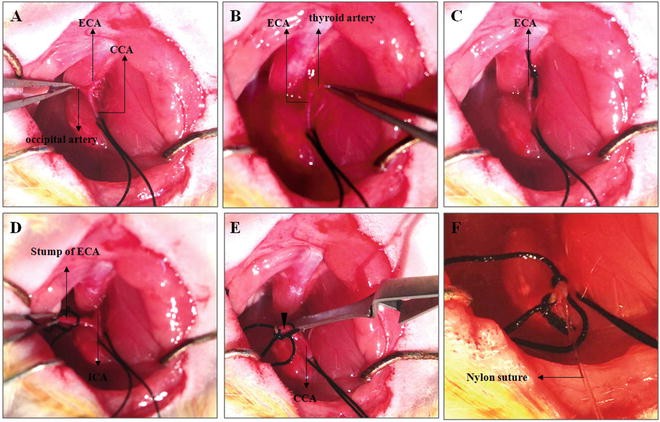
Schematic diagram of MCAO surgery process. Blood vessels are separated one by one. (a) Schematic diagram of ECA and occipital artery. (b) Schematic diagram of ECA and thyroid artery. (c) Schematic diagram of ECA ligated by suture. The occipital artery and the thyroid artery are cut by electrocoagulation. (d) Schematic diagram of stump of ECA and separated ICA. (e) Schematic diagram of the ICA clamped by microvessel clamp. Arrowhead indicate the position of incision for inserting suture. (f) Schematic diagram of insertion of nylon suture
-
11.
The occipital artery and thyroid artery are branches of the ECA that should be isolated and coagulated. When the ECA is fully exposed, the occipital artery is visible to the left of ECA (Fig. 4a), near the bifurcation of the CCA. Again, the occipital artery should be identified and separated from surrounding fascia, then ligated by electrocoagulation.
-
12.
The thyroid artery is visible to the right of ECA (Fig. 4b). Similar to the occipital artery, the thyroid artery is also separated from surrounding fascia and ligated by electrocoagulation.
-
13.
The ECA is dissected further distally, ligated, and coagulated along with the terminal lingual and maxillary artery branches, which are then divided (Fig. 4c, d). The resulting stump of the ECA will be used as the insertion point for the intraluminal suture.
-
14.
Loosely tie a 4-0 silk suture around the mobilized ECA stump (Fig. 4d), which is used for securing the intraluminal suture upon insertion and for preventing blood loss.
-
15.
Separate the ICA from its surrounding fascia and from the adjacent vagus nerve at the ICA and ECA branch (Fig. 4d). When isolating ICA, a tiny round muscle close to the branch is visible and must be separated from the ICA.
-
16.
Make sure the 4-0 suture threaded under the CCA is sufficiently tractioned by hemostats to prevent blood flow into the CCA at this time.
-
17.
A microvessel clamp is placed at the bottom edge of the CCA (Fig. 4e). It is best to place the microvessel clamp slightly away from the ICA and ECA branch.
-
18.
A tiny incision is made in the stump of ECA stump with iridectomy scissors at an angle of incidence (45° from parallel), while taking great care to not completely sever the artery. It is best to make this incision close to the end of the ECA stump. Once the artery is completely severed, another incision can be cut under that incision.


Troubleshooting: Massive hemorrhage from the incision = CCA and/or ICA is not completely clamped. If the ICA is not completely clamped, quickly clamp the stump of ECA under the incision with fine forceps, and adjust the microvessel clip to ensure the clip completely blocks arterial blood flow. Sometimes, the ICA is not fully isolated from connected fascia; as a result the clip can not fully block blood flow. As such, it is important to carefully separate the ICA from the connective fascia as well as the muscle. If the CCA is not completely clamped, verify that the tied suture is placing enough tension on the vessel to occlude blood flow.
-
19.
Insert intraluminal nylon suture through the proximal ECA. When the suture is gently inserted up to the microvessel clip, the silk suture around the ECA stump is tightened around the intraluminal nylon suture to prevent bleeding, and the microvascular clip can then be removed.
-
20.
The nylon suture is then gently advanced upward towards the ICA lumen. The position of the suture within the ICA lumen can be seen. Pull the stump of ECA towards the operator so that the ECA and ICA are manipulated into a straight line (Fig. 4f). This creates the easiest possible angle for suture insertion.
-
21.
Gently insert suture, following the path of the ICA towards the upper right. When the insertion length approaches 18 mm (the first marked dot), insert the suture more slowly (see Note 4 ). Resistance is felt and a slight curving of the suture or stretching of the ICA is observed, indicating that the blunted tip of the suture has passed the MCA origin and has reached the proximal segment of the anterior cerebral artery (ACA); which has a smaller diameter. At this point, the intraluminal suture has blocked the origin of the MCA. If the MCA is occluded, the CBF can drop to 20 % of baseline. The silk suture around the ECA stump is further tightened around the intraluminal nylon suture to secure its placement and to prevent any potential bleeding.
-
22.
Cut the protruding nylon intraluminal suture at about 0.5 cm away from the incision. Bury the stump of the suture into the tissue parallel with surrounding muscle fiber, be sure the remaining suture lying outside of the lumen does not lie perpendicular to the muscle. Suture the skin.
-
23.
Soften the bone wax by heat. The bone window is then sealed with the soft bone wax.
-
24.
Suture the scalp.
-
25.
Turn off the inhalational anesthesia. When the rat can spontaneous breathe, turn off breath machine. Place the animal in housing for recovery.
3.1.5 Reperfusion
-
1.
Induce anesthesia within the animal with 4 % enflurane and a 30:70 mixture of oxygen and nitrous oxide. A nose cone is used to continuously deliver the anesthetic gases.
-
2.
Open the incision to expose previously manipulated blood vessels. Clamp the CCA with microvessel clip. Pull out the nylon suture very slowly. When three marker points are taken out of the vessel, the nylon suture can be pulled back quickly. When the most distally marked point reaches the bifurcation of the CCA, clamp the ICA with microvessel clip, and proceed in pulling out the suture in its entirety. Coagulate the stump of the ECA. At this point the two microvessel clips can be removed.
-
3.
Suture the skin. Turn off the inhalational anesthesia. Place the animal in housing for recovery.
3.1.6 Behavioral Testing
Neurological deficits in animals are examined after any procedures. The deficits are scored using a five-score system [26].
-
1.
After reperfusion, the animal is held by the middle part of the tail and elevated from the tabletop. Observe the forelimb. 0, no observable deficits; 1, difficulty in fully extending the contralateral forelimb; 2, unable to extend the contralateral forelimb.
-
2.
Put the animal on open ground, if the rat cannot walk in a straight line, but instead moves in a circular course towards the direction contralateral to the infarcted side it is scored as a 3; Severe circling is scored as 4; falling to the contralateral side is scored as a 5 (see Note 5 ).
3.1.7 Important Tips
-
1.
Muscle tissue should be separated layer by layer. After cutting the skin, glands are visible. Cut the fascia along the midline of these glands (Fig. 3b). When anterior cervical muscles are exposed (Fig. 3c, d), do not cut muscle to avoid bleeding. Bluntly separate the two muscles with hemostats (separate muscles along the dotted line as indicated in Fig. 3b, d).
-
2.
When separating blood vessels, try to thoroughly clean the connective fascia from the blood vessel as much as possible. If the vessel is isolated clearly, it is easy to conduct subsequent steps including: electrocoagulation, placing microvessel clips, making incisions, and the eventual insertion of the intraluminal suture. This is especially important when making the incision at the stump of ECA using iridectomy scissors, so that the operator will not mistakenly cut completely though the outer membrane of the ECA (If mistakenly cut, repeated operation will result in cutting a bigger incision or severing the stump of ECA. For the purposes of this procedure the smaller this ECA incision is, the better). Because an oblique incision makes it easier for the initial insertion of the suture, it is better to make the incision at a 45° with the vascular wall. Be careful to not stretch the vessel too much, which could potentially cause vasospasm and, thus, insertion failure.
-
3.
If resistance is felt before full length of suture (18 mm) is inserted, this suggests that the suture could have been inserted into the pterygopalatine artery. Pull the suture out of the ICA up until the bifurcation of the CCA. Make another attempt to insert the intraluminal suture again, taking Note that insertion direction is important for correct placement. If the direction is straight or left, it is relatively easy to place the suture into the pterygopalatine artery. For beginners, the pterygopalatine artery can be ligated as described by Enrique Zea Longa et al. to avoid confusion. In brief, identify and dissect the ansa of the glossopharyngeal nerve at the origin of the pterygopalatine artery; this posteriorly directed extracranial branch of the ICA is ligated with 7-0 nylon suture close to its origin. At this point, the ICA is the only remaining extracranial branch of the CCA, allowing less room for error in placement.
-
4.
Try to avoid damage to the vagus nerve as it passes under the bifurcation of the CCA.
-
5.
Operator should be careful to insert the suture gently and smoothly. Despite this, insertion should be as fast as possible as prolongation of this procedure could lead to intravascular thrombosis.
-
6.
In order to reduce the possibility of subarachnoid hemorrhage and vasospasm, repeated suture inserts (over four times) into blood vessels should be avoided.
3.1.8 Exclusion Criteria (Failed Operation)
-
1.
If the depth of the suture insert is less than 18 mm (see above), and there is no obvious neurological deficits, the Zea Longa score is 0.
-
2.
Subarachnoid hemorrhage (SAH). Because hemorrhage also induces brain injury, it would be problematic to distinguish unintended brain damage from the intentional ischemia–reperfusion induced injury.
3.1.9 Cause of Death
Operator must first find out the cause of death, dissect rat brain, and look at whether there is SAH. SAH indicates that the suture is inserted too deep. Operator must pay attention to the length of insertion. If there is no bleeding, operator should observe whether there is a serious hemisphere edema. Any serious edema indicates that the death was caused by prolonged ischemia. As such, a short ischemic time period is required. If bleeding and/or serous cerebral edema is not apparent, operator should pay attention to animal status or whether the living environment was inadequate for any reason.
3.1.10 MCAO Complications
-
1.
Subarachnoid hemorrhage, which can be avoided by gentle operation.
-
2.
ICA thrombosis, which can be avoided by using heparinized sutures.
3.2 Intracerebral Hemorrhagic Models
Injection of collagenase VII is used to induce intracerebral hemorrhage (ICH) for hemorrhagic stroke evaluation [31].
3.2.1 Surgical Preparation
General surgical preparation is the same as described for MCAO preparation (Subheading 2.2, item 2).
3.2.2 Skull Preparation
Skull Preparation is the same as described in the part of CBF measurement (Subheading 2.2, item 3).
3.2.3 Thinning the Skull
-
1.
Set up microsyringe with 22-gauge needle on the stereotaxis frame.
-
2.
Collagenase VII is injected into the right striatum (from bregma: 1.2 mm posterior, 3.5 mm lateral, and 3.5 mm depth). Needle is located aiming the bregma. And then locate skull window by stereotaxic frame and mark a puncture site using a marker pen (stereotactic coordinates from bregma: 1.2 mm posterior, 3.5 mm lateral). Take the microsyringe away.
-
3.
A micro drill and 1 mm carbide ball bit is used to gently thin the skull over the marked region. Once the outer layer of the skull is removed, the spongy bone layer can be removed with gentle scraping using a dull forceps. The remaining layer can be thinned further and as needed with the carbide bit, with great care so as to not completely break through.
3.2.4 Collagenase VII Injection
-
1.
Draw up 1 μL Collagenase VII into the microsyringe. Ensure that there are no air bubbles in the syringe.
-
2.
Move the needle back to the point just over the skull window. Screw the needle gently onto the surface of the skull window. Screw the needle gently into the brain to about a 4 mm depth and then withdraw 0.5 mm using stereotactic coordinates (Fig. 4).
-
3.
Very slowly screw the stylet of the syringe (at speed 0.1–0.2 μL/min). The entire injection procedure should last 5–10 min.
-
4.
The needle is left in place for 5 min to allow collagenase infusion and action.
-
5.
Slowly withdraw the needle at a speed of about 1 mm/min (see Note 6 ).
-
6.
Soften the bone wax by heat. Bone window is sealed with the soft bone wax.
-
7.
Suture the scalp.
-
8.
Turn off the inhalational anesthesia. When the animal can spontaneously breathe, then turn off the breath machine. Place the animal in housing for recovery.
4 Notes
-
1.
Depending on the ambient temperature, place a ceramic heat lamp over the rat to prevent a drop in body temperature while the heating pad stabilizes.
-
2.
In order to reduce the possibility of bleeding from subcutaneous tissue, do not cut subcutaneous tissue with scissors and use hydrogen peroxide.
-
3.
Because trachea is to the right of the scalenus muscle, make sure that the trachea is not compressed by retractor #3.
-
4.
The insertion length depends on the animal’s body weight. If the insert length is over 20 mm (the third marked dot), and the suture can still be inserted, please do not insert any more.
-
5.
If the animal does not walk, operator can pinch the tip of the tail. Do not stand beside the animal so as to avoid disturbing it.
-
6.
Increasing the delay in needle withdrawal and infusion course is important for successful generation of the ICH model.
References
Go AS, Mozaffarian D, Roger VL, Benjamin EJ, Berry JD, Borden WB, Bravata DM, Dai S, Ford ES, Fox CS, Franco S, Fullerton HJ, Gillespie C, Hailpern SM, Heit JA, Howard VJ, Huffman MD, Kissela BM, Kittner SJ, Lackland DT, Lichtman JH, Lisabeth LD, Magid D, Marcus GM, Marelli A, Matchar DB, McGuire DK, Mohler ER, Moy CS, Mussolino ME, Nichol G, Paynter NP, Schreiner PJ, Sorlie PD, Stein J, Turan TN, Virani SS, Wong ND, Woo D, Turner MB (2013) Executive summary: heart disease and stroke statistics—2013 update: a report from the American Heart Association. Circulation 127:143–152
Wang G, Zhang Z, Ayala C, Dunet DO, Fang J, George MG (2014) Costs of hospitalization for stroke patients aged 18-64 years in the United States. J Stroke Cerebrovasc Dis 23:861–868
Krafft PR, Bailey EL, Lekic T, Rolland WB, Altay O, Tang J, Wardlaw JM, Zhang JH, Sudlow CL (2012) Etiology of stroke and choice of models. Int J Stroke 7:398–406
James ML, Warner DS, Laskowitz DT (2008) Preclinical models of intracerebral hemorrhage: a translational perspective. Neurocrit Care 9:139–152
Ma Q, Khatibi NH, Chen H, Tang J, Zhang JH (2011) History of preclinical models of intracerebral hemorrhage. Acta Neurochir Suppl 111:3–8
Bacigaluppi M, Comi G, Hermann DM (2010) Animal models of ischemic stroke. Part two: modeling cerebral ischemia. Open Neurol J 4:34–38
Andaluz N, Zuccarello M, Wagner KR (2002) Experimental animal models of intracerebral hemorrhage. Neurosurg Clin N Am 13:385–393
Carmichael ST (2005) Rodent models of focal stroke: size, mechanism, and purpose. NeuroRx 2:396–409
Durukan A, Tatlisumak T (2007) Acute ischemic stroke: overview of major experimental rodent models, pathophysiology, and therapy of focal cerebral ischemia. Pharmacol Biochem Behav 87:179–197
Emiru T, Bershad EM, Zantek ND, Datta YH, Rao GH, Hartley EW, Divani AA (2013) Intracerebral hemorrhage: a review of coagulation function. Clin Appl Thromb Hemost 19:652–662
Bogousslavsky J, Van Melle G, Regli F (1988) The Lausanne Stroke Registry: analysis of 1,000 consecutive patients with first stroke. Stroke 19:1083–1092
Fischer U, Arnold M, Nedeltchev K, Brekenfeld C, Ballinari P, Remonda L, Schroth G, Mattle HP (2005) NIHSS score and arteriographic findings in acute ischemic stroke. Stroke 36:2121–2125
Saqqur M, Uchino K, Demchuk AM, Molina CA, Garami Z, Calleja S, Akhtar N, Orouk FO, Salam A, Shuaib A, Alexandrov AV (2007) Site of arterial occlusion identified by transcranial Doppler predicts the response to intravenous thrombolysis for stroke. Stroke 38:948–954
Rordorf G, Koroshetz WJ, Copen WA, Cramer SC, Schaefer PW, Budzik RF Jr, Schwamm LH, Buonanno F, Sorensen AG, Gonzalez G (1998) Regional ischemia and ischemic injury in patients with acute middle cerebral artery stroke as defined by early diffusion-weighted and perfusion-weighted MRI. Stroke 29:939–943
Bivard A, Levi C, Spratt N, Parsons M (2013) Perfusion CT in acute stroke: a comprehensive analysis of infarct and penumbra. Radiology 267:543–550
Strbian D, Durukan A, Tatlisumak T (2008) Rodent models of hemorrhagic stroke. Curr Pharm Des 14:352–358
MacLellan CL, Silasi G, Auriat AM, Colbourne F (2010) Rodent models of intracerebral hemorrhage. Stroke 41:S95–S98
Rosenberg GA, Mun-Bryce S, Wesley M, Kornfeld M (1990) Collagenase-induced intracerebral hemorrhage in rats. Stroke 21:801–807
Manaenko A, Chen H, Zhang JH, Tang J (2011) Comparison of different preclinical models of intracerebral hemorrhage. Acta Neurochir Suppl 111:9–14
Choudhri TF, Hoh BL, Solomon RA, Connolly ES Jr, Pinsky DJ (1997) Use of a spectrophotometric hemoglobin assay to objectively quantify intracerebral hemorrhage in mice. Stroke 28:2296–2302
Clark W, Gunion-Rinker L, Lessov N, Hazel K (1998) Citicoline treatment for experimental intracerebral hemorrhage in mice. Stroke 29:2136–2140
MacLellan CL, Gyawali S, Colbourne F (2006) Skilled reaching impairments follow intrastriatal hemorrhagic stroke in rats. Behav Brain Res 175:82–89
Beray-Berthat V, Delifer C, Besson VC, Girgis H, Coqueran B, Plotkine M, Marchand-Leroux C, Margaill I (2010) Long-term histological and behavioural characterisation of a collagenase-induced model of intracerebral haemorrhage in rats. J Neurosci Methods 191:180–190
Takamatsu Y, Ishida A, Hamakawa M, Tamakoshi K, Jung CG, Ishida K (2010) Treadmill running improves motor function and alters dendritic morphology in the striatum after collagenase-induced intracerebral hemorrhage in rats. Brain Res 1355:165–173
Koizumi J, Yoshida Y, Nakazawa T, Ooneda G (1986) Experimental studies of ischemic brain edema: a new experimental model of cerebral embolism in rats in which recirculation can be introduced in the ischemic area. Jpn Stroke J 8:1–8
Longa EZ, Weinstein PR, Carlson S, Cummins R (1989) Reversible middle cerebral artery occlusion without craniectomy in rats. Stroke 20:84–91
Belayev L, Alonso OF, Busto R, Zhao W, Ginsberg MD (1996) Middle cerebral artery occlusion in the rat by intraluminal suture. Neurological and pathological evaluation of an improved model. Stroke 27:1616–1622, discussion 1623
Laing RJ, Jakubowski J, Laing RW (1993) Middle cerebral artery occlusion without craniectomy in rats. Which method works best? Stroke 24:294–297, discussion 297–298
Shimamura N, Matchett G, Tsubokawa T, Ohkuma H, Zhang J (2006) Comparison of silicon-coated nylon suture to plain nylon suture in the rat middle cerebral artery occlusion model. J Neurosci Methods 156:161–165
Ding Y, Li J, Rafols JA, Phillis JW, Diaz FG (2002) Prereperfusion saline infusion into ischemic territory reduces inflammatory injury after transient middle cerebral artery occlusion in rats. Stroke 33:2492–2498
Matsushita K, Meng W, Wang X, Asahi M, Asahi K, Moskowitz MA, Lo EH (2000) Evidence for apoptosis after intercerebral hemorrhage in rat striatum. J Cereb Blood Flow Metab 20:396–404
Acknowledgments
This work was partially supported by the program of National Natural Science Foundation of China (81573867), and Scientific Special Funding of Capital Health Development (No. 2011-1001-03).
Author information
Authors and Affiliations
Corresponding author
Editor information
Editors and Affiliations
Rights and permissions
Copyright information
© 2016 Springer Science+Business Media New York
About this protocol
Cite this protocol
Ren, C., Sy, C., Gao, J., Ding, Y., Ji, X. (2016). Animal Stroke Model: Ischemia–Reperfusion and Intracerebral Hemorrhage. In: Kobeissy, F., Dixon, C., Hayes, R., Mondello, S. (eds) Injury Models of the Central Nervous System. Methods in Molecular Biology, vol 1462. Humana Press, New York, NY. https://doi.org/10.1007/978-1-4939-3816-2_21
Download citation
DOI: https://doi.org/10.1007/978-1-4939-3816-2_21
Published:
Publisher Name: Humana Press, New York, NY
Print ISBN: 978-1-4939-3814-8
Online ISBN: 978-1-4939-3816-2
eBook Packages: Springer Protocols