
Abstract
The aim of this chapter on Support Foundations is to provide a résumé of the previous Cigré publications, prepared by SCB2 WG07 and WG23, on their design, installation and testing; where appropriate these have been revised to include current design and installation practice. An underlying theme of these publications is that the support foundations, unlike the other Overhead Line (OHL) components, e.g. conductors, insulators and support, are constructed partly or wholly in-situ, in a medium (the ground), which does not have constant properties and is unique at each support site. The installation of a typical OHL support foundation is shown in Figure 13.1.
Originally published by Cigré, 2014, under the ISBN 978-2-85873-284-5.
Republished by Springer International Publishing Switzerland with kind permission.
Access provided by CONRICYT-eBooks. Download reference work entry PDF
Keywords
These keywords were added by machine and not by the authors. This process is experimental and the keywords may be updated as the learning algorithm improves.
FormalPara Executive SummaryThe aim of this chapter on Support Foundations is to provide a résumé of the previous Cigré publications, prepared by SCB2 WG07 and WG23, on their design, installation and testing; where appropriate these have been revised to include current design and installation practice. An underlying theme of these publications is that the support foundations, unlike the other Overhead Line (OHL) components, e.g., conductors, insulators and support, are constructed partly or wholly in-situ, in a medium (the ground), which does not have constant properties and is unique at each support site. The installation of a typical OHL support foundation is shown in Figure 13.1.

Installation of a 330 kV reinforced concrete raft foundation.

Interaction process.

Diagrammatic representation of foundation design & installation process.

Failure of a 500 kV suspension tower drilled shaft foundation.

Quantified foundation design hazard identification and risk assessment.

Qualitative geotechnical hazard identification and risk assessment.


Diagrammatic representation of foundation installation QA requirements.

Reduction in environmental impact.

Diagrammatic representation of foundation interaction with the ground.

Free body diagram support type – applied foundation loading.

Diagrammatic representation of dynamic loading on support foundations.

Diagrammatic representation of interrelationship between support types and principal foundation categories

Spread footings.

Typical shallow pyramid and chimney (a), and grillage (b) foundations.

Drilled shaft foundations.

Anchor foundations.

Typical spread anchor (a) and pre-cast concrete guy ‘deadman’ (b) foundations.

Monoblock foundations.

Reinforced concrete raft (slab) foundation for a 110 kV lattice steel tower.

Typical stepped block spread foundation – 220 kV Kama River Crossing.

Driven steel tube piles with steel grillage – lattice steel tower leg connection.

Steel screw piles with steel grillage – 500 kV portal guyed tower mast base.

Pre-cast concrete pile – Portal guyed tower mast base.

Pre-cast concrete pile – Portal guyed tower guy anchor.

Diagrammatic representation of the site investigation process.

Geotechnical Data Summary (existing OHL).

Geotechnical Hazards.

Combined cable percussion and rotary boring rig (a. existing tower, b. new tower site).

Free body diagram – spread foundations (compression and uplift).

Free body diagram – Drilled shaft foundation (Separate).

Free body diagram – Drilled shaft foundation (Compact).

Free body diagram – Ground anchor (uplift).

Spread foundations – interaction diagram (Numbers in red refer to Table 13.8).

Separate foundations incorrect concrete mix design and curing (Key 8).

Drilled shaft foundation – interaction diagram (Numbers in red refer to Table 13.9).

Drilled shaft foundations failure to adequately remove all of excavation material during concrete placing (Key 7 & 10).

Micropiles and ground anchors – interaction diagram (Numbers in red refer to Table 13.10).

Probability density function for foundation strength test data.

Foundation data sheet.
Within this overall context of the variability of the ground, i.e., soil, rock and ground water, the concept of an “Integrated approach” has been developed such that there are no artificial boundaries between the design and installation process, i.e., the design, including the geotechnical studies, and the installation activities should be seamless; with a continuous exchange of information between all parties, e.g., the client, the foundation designer(s), the ground investigation contractor and the installation contractor(s), from the initial feasibility stage through to the foundation installation. An integral part of this approach is the ongoing need for hazard identification and corresponding risk assessments to be undertaken; thereby ensuring that health and safety, environmental, project and financial management issues are adequately considered and resolved throughout the project. Correspondingly, the application of this approach has been maintained throughout this chapter.
Section 13.1 provides an introduction to the concept of an “Integrated Approach”, together with an example of the serous consequences of not adopting this proposed approach; which was effectively the result of a failure in communications between the foundation designer and the installation contractor. Continuing on the theme of an “Integrated Approach”, Section 13.2 considers the requirements in respect of Health and Safety, the application of Risk Assessment, Environmental Impacts and potential mitigation measures in respect of foundation installation including access development, together with an overview in respect of the Quality Assurance measures required during the different phases of the works.
The design of the support foundations has been divided between Sections 13.3, 13.4 and 13.5 and is based on Cigré Electra 131, 149 and 219, and Cigré TB 206, 281, 308, 363 and 516. Section 13.3 considers the design basis, the interdependency between foundation and ground both in terms of the interaction between the foundation loading and the ground, and the affects on the ground during the foundation installation. Also considered in this section are the affects of applied static and dynamic loadings on the foundation, and an overview of the different foundation types. Section 13.4 considers the Site Investigation requirements, especially the need for ongoing geotechnical assessment during the foundation installation. The geotechnical and structural design of the three typical foundation types: Spread footings, Drilled shafts and Ground anchors/micropiles is considered in Section 13.5, including the interaction with the installation process. Also considered in this section is the calibration of the theoretical foundation model against full-scale foundation test results, together with a précis of new developments in the analysis of spread footings under applied uplift loadings.
Section 13.6 considers foundation testing both full-scale and model testing including the use of centrifuge modelling techniques. Although, this section is generally based on Cigré Special Report 81 and the subsequent IEC standard 61773, concerns are raised regarding the suitability of the maintained load test, if the behaviour of the foundation under gust wind loading or other dynamic loadings is to be investigated.
The installation of the foundations is considered in Section 13.7 and provides a summary of the main installation activities, previously considered in Cigré TB 308, e.g., temporary works, foundation excavation, concreting, backfilling, etc. The refurbishment and upgrading of existing foundations is considered Section 13.8 and is based on Cigré TB 141. Topics reviewed in this section include foundation deterioration, foundation assessment, refurbishment and upgrading.
The outlook for the future in respect of the need for further research into the complete support-foundation system, the permissible displacements of foundation-support system, the design of foundations in respect of application of dynamic loadings is considered Section 13.9. While, Section 13.10 provides a brief summary of this chapter.
A bibliography of the main documents quoted in this chapter is also provided.
FormalPara GlossaryTo assist the reader of this chapter on support foundations, a glossary of terms which have not been explained in the relevant text is given below:
-
Alluvium: Unconsolidated, fine-grained loose material (silt or silty-clay) brought down by a river and deposited in its bed, floodplain, delta, estuary or in a lake.
-
Brownfield site: A site or part of a site that has been subject to industrial development, storage of chemicals or deposition of waste, and which may contain aggressive chemicals in residual surface materials or ground penetrated by leachates.
-
Cone Penetration Test [CPT]: Comprises pushing a standard cone into the ground at a constant rate and electrically recording the resistance of the cone point and the side friction on the cone shaft perimeter.
-
Expansive soil: A soil which is subject to shrink-swell phenomena.
-
Foundation assessment: The process of interpreting information collected during the foundation inspection, geotechnical investigation, full-scale foundation testing, in service data/experience, etc., to estimate the current strength/condition of the foundation and/or predict the useful service life under the original/increased design loads.
-
Foundation refurbishment: All methods used to extensively renovate or repair the foundations, thereby restoring their original design strength and condition.
-
Foundation upgrading: All methods used to increase the strength of the foundations to resist the increased applied loads, arising from upgrading and/or uprating the OHL.
-
Fluvial deposits: Produced by or due to the action of water derived from melting glaciers or ice sheets.
-
Geotechnical hazard: An unforeseen geotechnical condition, inappropriate design or construction method arising from a poor understanding of the known ground conditions,
-
Hold Point: A stage in the material procurement or workmanship process beyond which work shall not proceed without the documented approval of designated individuals or organisations.
-
LIDAR: Light Detection and Ranging, a technique using light sensors to measure the distance between the sensor and the target object. The equipment can be both airborne or ground based.
-
Muff concrete: Muff or reveal concrete is used to form a watershed to the top of a concrete foundation, particularly the chimney. This secondary concreting is frequently undertaken after the main concrete has already cured and hardened.
-
Notification Point: A stage in the material procurement or workmanship process for which advance notice of the activity is required to permit the witnessing of the activity.
-
Organic soil: A soil consisting of organic material, derived from plants, e.g., peat.
-
Quality Assurance: Part of the quality management, focussed on providing confidence that quality requirements are fulfilled. Quality Assurance has both internal and external aspects, which in many instances may be shared between the contractor (1st party), the customer (2nd party) and any regulatory body (3rd party) that may be involved.
-
Quality Control: The operational techniques and activities that are used to fulfil requirements for quality. Quality control is considered to be the contractor’s responsibility.
-
Standard Penetration Test [SPT]: Is a dynamic penetration test undertaken using a standard test procedure and comprises driving a thick wall sample tube into the ground at the bottom of the borehole by blows from a standard weight falling through a standard distance. The resistance to penetration, expressed by “N” (blow count) is measured by the number of blows required to give the penetration through 300 mm and thereby gives indication of the density of the ground.
-
Working Load: An un-factored load derived from a climatic event with an undefined return period.
Where reference is made to a Cigré TB, or other publications, etc., the full corresponding cross-reference, e.g., Cigré TB 141 (Cigré 1999), is only stated initially; subsequently only an abridged reference, e.g., Cigré TB 141 has been used.
In Section 13.5.3 “Foundation Design – Geotechnical and Structural” cross-reference has been made to publication by many different authors by name and date; however, no space is available in the References to list all the details and correspondingly where the date reference is shown, thus (1943*), the reader should refer to the Bibliography in Cigré TB 206.
FormalPara AcknowledgementsAcknowledgements are given to Mr M J Vanner, Dr A M DiGioia Jr and Mr K Yamatani, for their time in reviewing this chapter and for their helpful comments and suggestions. In addition, acknowledge is also given to the Cigré SCB2 WG23 Australasian representative Mr G Paterson for his helpful comments.
The following figures have been reproduced by courtesy of the following organisations:
-
Downer Australia: Figures 13.1, 13.48 (bottom), 13.49, 13.50 (bottom), 13.53, 13.55 (top), 13.58 and 13.59a.
Figure 13.40 
Full-scale uplift test arrangement for P&C concrete foundation.
Figure 13.41 
Time – Load – Displacement plot for a full-scale uplift test.
Figure 13.42 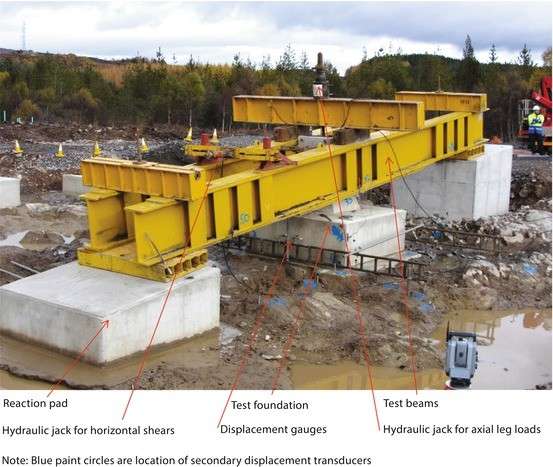
Full-scale test arrangement for Rock Anchor foundation.
Figure 13.43 
Full-scale testing of an existing foundation – support in-situ. (Note: Bottom tower leg disconnected and removed during the test)
Figure 13.44 
Proof testing of individual rock anchors.
Figure 13.45 
Diagrammatic representation of foundation installation activities. (Note: Primary activities refer to the main foundation installation, i.e., for piled foundations the installation of the individual piles, while the secondary activity refers to the construction of the pile cap.
Figure 13.46 
Temporary working platform, including the use of gabion baskets for slope stability.
Figure 13.47 
Foundation excavation installation of temporary support system (sheet steel piles).
Figure 13.48 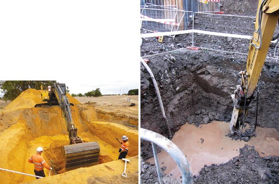
Foundation excavation in soil (left) and rock (right).
Figure 13.49 
Installation of Bored piles.
Figure 13.50 
Installation of Driven piles ‘H’ section (left) and tubular steel (right).
Figure 13.51 
Rock anchor installation.
Figure 13.52 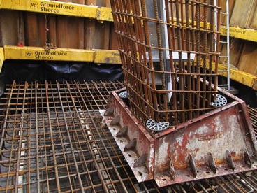
Steel formwork.
Figure 13.53 
Disposal formwork.
Figure 13.54 
Intermediate stage concrete pad cast prior to placing stub and chimney formwork.
Figure 13.55 
Stub setting.
Figure 13.56 
Transportation of concrete – helicopter.
Figure 13.57 
Placing of concrete using a concrete pump.
Figure 13.58 
Placing of concrete using chute (left) and skip (right).
Figure 13.59 
Backfill compaction (open excavation) (left). Backfill compaction (temporary support system in place)(right).
-
NIKES, JSC SevZap NTC Saint-Petersburg: Figures 13.20 to 13.24 and 13.66.
Figure 13.60 
Diagrammatic representation of foundation assessment process.
Figure 13.61 
(a) Effect of AAR on concrete. (b) Steelwork corrosion.
Figure 13.62 
Intrusive foundation inspection.
Figure 13.63 
Foundation upgrade – Use of precast concrete blocks.
Figure 13.64 
Foundation upgrading – Installation of micropiles.
Figure 13.65 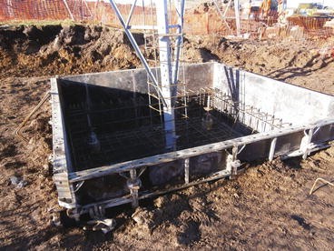
Foundation upgrading – Installation of micropile reinforced concrete cap.
Figure 13.66 
Foundation upgrading using steel screw piles and steel beam.
-
SSE plc: Figures 13.8, 13.46, 13.56, 13.57, 13.62, 13.63, 13.64, and 13.65.


13.1 Introduction
OHL support foundations are the interlinking component between the support and the in-situ soil and/or rock, i.e., the ground. However, since the ground does not have constant properties and is unique at each support location, there is no other element of the OHL about which less is known. To ensure that the OHL achieves its required level of reliability, it is preferable that the support foundations, the ground and the ground water, either free flowing or as pore pressure, should be viewed as an interdependent system, with the properties and behaviour of the constituent parts of the system adequately identified. Furthermore, the ground’s behaviour depends, to a degree, on the foundation installation techniques and although many sites are relatively insensitive to construction activities, skill and knowledge are required to evaluate if this is the case, for the site in question.
Consequentially, based on the premise outlined above, the following factors should be considered in the design, installation, refurbishment and upgrading of the support foundations:
-
Support type, support base size or diameter and applied loadings;
-
Foundation type, e.g., drilled shaft, pad and chimney, steel grillages, piles, etc.;
-
Geotechnical conditions, e.g., soil or rock type and condition, ground water level, and whether “geotechnical hazards”, e.g., landslides, rock falls, ground subsidence, aggressive ground conditions, etc. are present;
-
Permanent or temporary installation;
-
Primary installation, refurbishment or upgrading of existing foundations;
-
Environmental, e.g., topography, climate, contamination, etc.;
-
Resources, e.g., foundation materials, labour, construction plant, foundation installation temporary works requirements, programme and financial constraints;
-
Constraints, e.g., environmental impact, client requirements, third parties with respect to access, use of the surrounding land, etc.;
-
Health, safety and quality management requirements.
To ensure that all of the factors, listed above, are adequately considered, there should be no artificial boundaries between the initial feasibility, planning, design and installation process, i.e., the design, including the geotechnical studies, and the installation activities should be seamless; with a continuous exchange of information between all parties, e.g., the client, the foundation designer(s), the ground investigation contractor and the installation contractor(s). In addition, to the obvious interaction between the design and installation process, the interaction with respect to: environmental constraints, site access, health and safety, quality and resource management, should all be taken into account and continuously evaluated throughout the design and installation activities, i.e., from the initial OHL routing or the initial reassessment of an existing OHL, through to the final site reinstatement. The interaction process is shown diagrammatically in Figure 13.2, while a detailed diagrammatic representation of the foundation design and installation process is shown in Figure 13.3.
As stated above, good communications between the respective parties, i.e., the client, the client’s representatives, the foundation designer(s), the installation contractor(s) and any external bodies, form an essential part of the overall design and installation process and will have a direct influence on the successful outcome of the project, in respect of quality, safety and the environmental impact.
The client and/or his representatives should ensure that their technical requirements are clearly stated in the appropriate technical specification and that for any work on existing support foundations the “as-built” foundation drawings, calculations and associated health, safety and environmental information are made available, at the earliest opportunity, to both the foundation designer(s) and the installation contractor(s).
The foundation designer should ensure that all the information used in the design and especially any assumptions made in respect of the ground conditions and the installation contractor’s method of working are made available to all appropriate parties. The information should, as a minimum include the foundation installation drawings, the geotechnical report and the initial design hazard review and risk assessment. Furthermore, the necessity to undertake ongoing geotechnical assessment during the foundation installation should be clearly stated.
The foundation installation contractor should ensure that all the appropriate information is considered in the preparation of the: installation procedures, temporary works design, construction health and safety plan, site risk assessment, and associated installation method statements. Critically, the foundation installation contractor’s site staff and operatives should ensure that if there are any changes in the ground conditions from those assumed in the foundation design, e.g., variations in ground water level or soil properties, the foundation designer is immediately informed and, if necessary, work on-site suspended until a reassessment of the design has been made and, if appropriate, a revision to the method statement undertaken. Correspondingly, the foundation designer and/or foundation installation contractor should ensure that the services of a geotechnical engineer are readily available on site.
13.1.1 Reasons for the Failure
The serious consequences of failing to verify the assumed geotechnical design parameters during foundation installation are shown in Figure 13.4 and emphasise the need for effective communications between the foundation designer and the installation contractor.
Failure due to a combination of circumstances, but basically due to a lack of communications:
-
Tower failure precipitated by high Santa Ana wind prior to commissioning of the line;
-
Based on the geology of OHL route the foundation designer assumed cohesive soil and decided to use a drilled shaft foundation with an under-ream (bell) at the base;
-
No on-going geotechnical assessment undertaken during construction and no one noticed that the soil was granular;
-
During concreting the side walls of the shaft collapsed, especially at the bottom;
-
Installation contractor did not measure quantity of concrete poured, therefore no check against theoretical volume of concrete and hence whether the foundation was installed correctly.
13.2 Health, Safety, Environmental Impacts and Quality Assurance
13.2.1 Introduction
One of the primary requirements of the “Integrated Approach” is the necessity to continuously evaluate the potential Health, Safety, Environmental and Quality issues throughout the foundation design and installation activities, i.e., from the initial OHL routing or the initial re-assessment of an existing OHL, through to the final site reinstatement. To ensure that this evaluation is undertaken in a systematic manner and can be effectively communicated to all parties, the use of on-going hazard identifications and risk assessments should be considered.
13.2.2 Health and Safety: General
Health and Safety (H&S) requirements in respect of foundation installation have been extensively covered in Section 5 of Cigré TB 308 (Cigré 2006) and although there have been changes in the appropriate statutory legislation since the publication of the Cigré TB, e.g., the UK’s “Construction (Design and Management) Regulation was revised in 2007, the fundamental principles remain unchanged, i.e.:
-
There is a “Duty of Care”, so far as reasonable practical on employers in respect of their employees, persons not in their employ or third parties (e.g., general public), who may be affected by their work. This applies equally to clients and contractors;
-
Similar principles also apply in respect of consultants and the self-employed;
-
The “Duty of Care” relates to the health and safety of their employees, provision of a safe working environment, safe systems in respect of plant, materials, transport, provision of adequate training, etc.;
-
Employees shall take reasonable care of their own safety and that of others.
Similar principles also apply in respect of any geotechnical investigations undertaken during all stages of the project, from the initial OHL routing to the on-going geotechnical assessments during the foundation installation.
Consequentially, there is a need to identify and where possible eliminate the hazards, but where this is not possible, to reduce the residual risks to an acceptable level. This hierarchy of hazard elimination and risk reduction can be summarised as:
-
Eliminate: By removing the hazard, e.g., rerouting the affected section of the OHL;
-
Reduce: Use of alternative installation techniques e.g., changing from bored to driven piling on sites affected by contamination, where it is not possible to relocate the support;
-
Inform: Provision of information on the residual risks, such that the foundation installation contractor can develop the appropriate Method Statement;
-
Control: Provision of appropriate barriers, warning notices, personal protective equipment/clothing, training, etc.
Correspondingly, to apply this hierarchy of hazard elimination a formal risk assessment should be undertaken.
13.2.3 Risk Assessment
A risk assessment is a systematic identification of what the hazards are, the probability of “harm” occurring and the possible consequence of the harm and its severity, i.e., the “risk”. In this context “harm” can be considered as injury or death (health and safety), spread of pollutants into an aquifer (environmental) or cost overruns (project considerations).
Although a risk assessment is normally considered in respect of H&S during the installation activities, in reality it should be extended to include all aspects of the design, construction, the subsequent operation, maintenance, refurbishment/upgrading, to the final dismantling and include not only the H&S issues, but also the environmental impacts and project considerations.
The risk assessment can be either qualitative or quantitative. In the former engineering judgement is used in respect of severity and frequency rating; whereas, in the latter numerical values are assigned to both. A precise estimate of the risk is not required under most conditions and therefore a qualitative approach could be selected, provided its limitations are recognized. For examples three categories of severity could be assumed, e.g., High (fatality), Medium (injury causing short term disability) and Low (minor injury) and similar categories could be assumed in respect of the likelihood of the “harm” actually occurring.
When the risk is considered to be unacceptable, the adoption of the appropriate mitigation (control) measures would be required; these could range from changes in the proposed OHL route, the adoption of different foundation types, different installation techniques or delaying the work such that it is, for example outside the bird breeding season.
Extracts from a quantified foundation design hazard identification and risk assessment is shown in Figure 13.5 while a qualitative geotechnical desk study hazard identification and associated risk assessment is shown in Figure 13.6.
Although, the two previous examples are related to the design activities, similar principles should be adopted for the actual foundation installation activities. An extract from a typical risk assessment for foundation installation for a concrete pyramid/pad and chimney foundation is shown in Table 13.1. For convenience, it has been assumed that risk assessments for material delivery to site, storage of material on site, safe use of lifting gear, the effect of substances hazardous to health e.g., cement, etc., have already been undertaken.
For further details regarding risk assessment reference should be made to Section 3.12 of Cigré TB 516 (Cigré 2012) and Section 5.4 of Cigré TB 308.
13.2.4 Environmental Impact
Both the local environment and the communities adjacent to the route of the OHL are affected by the construction activities, with access construction and foundation installation having a major impact. Consequentially, the adoption of the appropriate mitigation measures can significantly reduce the environmental impact of an OHL during the construction phase.
Potential environmental impacts, which may occur, during access construction and foundation installation activities include:
-
Increase in traffic on local roads, especially as regards the delivery of plant, equipment and materials, e.g., excavation or piling equipment, supply of ready-mix concrete;
-
Impact of access tracks on the environment;
-
Disturbance to the land and vegetation and removal of trees;
-
Noise, dust and vibrational pollution;
-
Soil erosion and pollution of water courses;
-
Disturbance to birds and other fauna;
-
Foundation installation, including the dispersion of contaminated soil or ground water.
Other impacts that may occur are:
-
Disturbance to farming, agriculture and other business or leisure activities;
-
The client’s relationships with landowners, grantors, local authorities and other statutory or public agencies;
-
Disturbance of archaeological remains.
While it is not possible to completely remove all of the potential impacts, described above, it is possible reduce their impact and therefore to a degree, the public’s and/or landowners/grantors perception of the affect of OHL construction on the environment.
As an integral part of the planning and consent process, normally new OHLs are subject to an environmental assessment. This also usually applies to the constructional activities associated with the refurbishment and/or upgrading of existing OHLs. Both an initial desk study and site assessments would be undertaken to establish which of the support sites are likely to be affected by environmental and/or archaeological constraints. The area to be considered would possibly extend to include a buffer zone 500 m wide either side of the route centre line and including the access roads/tracks.
Where OHL support sites are located in designated areas of importance under international conventions or by national regulations, specific studies will require to be undertaken in consultation with the appropriate statutory bodies. In conjunction with the environmental studies, a separate study is usually undertaken in respect of determining whether any support site, or the area adjacent to any site, may have an archaeological interest.
Once the studies outlined above have been completed and depending on their outcome in terms of the environmental and archaeological impacts, it may be necessary to prepare a site environmental plan, detailing the mitigation measures required.
With regards to the actual design of the foundation, consideration should be given to the use of alternative foundation types, which may lessen the overall environmental impact, e.g., the use of micropiles, driven steel tube piles, helical screw anchors, etc., as an alternative to conventional reinforced concrete spread foundations. However, this may need to be counterbalanced against the possible temporary increase in environmental impact during the installation phase from the use of larger plant and equipment.
Other environmental mitigation measures, which could be considered at the design stage (in the widest environmental context), are the use of alternative cementious materials to Portland cement, e.g., use of pulverised fly ash (pfa) or ground granulated blast furnace slag (ggbs), which in themselves are waste by-products from other industrial processes or the use of reclaimed aggregates, including those derived from waste ready-mixed concrete. The latter overcomes the environmental hazard related to the disposal on-site of the cement slurry arising from the washing out of ready mix concrete mixer trucks.
The successful planning and construction of site access roads or tracks, modifications to field fences and/or hedges, gateways, etc. (accommodation works), will obviously make a significant contribution to the overall impact of the project, both in terms of the environmental impact and the relationship with landowners, grantors and the general public, and where appropriate the environmental protection agencies. Consideration will also be required in respect of the use of public roads by site traffic, e.g., road width, weight limits on bridges, clearance to structures or OHLs, location of schools or other areas where there is a concentration of children, etc. Any traffic management scheme will need to be agreed with the responsible authorities. Figure 13.8a shows the use of a height barrier to identify restricted height clearance from an overrunning OHL.
Wherever possible, use should be made of existing tracks as access roads/tracks; although, they may need to be upgraded, depending on the existing wearing surface, drainage conditions, general ground conditions and the anticipated volume and size/weight of site traffic using the proposed access. Consideration may also need to be made in the respect of provision of temporary bridging of water courses or drainage systems, see Figure 13.8b. The removal of hedges, fences, widening of gateways and possible insertion of new entrances from the public highway, will all need control and agreement with the appropriate parties. In addition, the landowner/grantor should not be put to any inconvenience in gaining access to his land/property by the installation contractor’s use of the access route.
Where new access tracks are required, these should wherever possible, follow the natural contours of the terrain to minimise cut and fill quantities. Care should also be taken to minimise the effect of erosion caused by water runoff and siltation of water courses. Consideration should also be given to the use of special temporary access systems, e.g., wood or aluminium track way panels or temporary stone roads (i.e., crushed imported stone laid on a geotechnical membrane), see Figure 13.8a, b. As an alternative to the use of special temporary access systems, consideration should be given to the use of low ground pressure vehicles, thereby preventing excessive soil compaction or damage; Figure 13.8c shows the use of an excavator fitted with wide tracks for use in moorland terrain with peat present.
As an alternative to the use of vehicular transport, it may be necessary to consider the transportation of materials, equipment and site operatives by helicopter. One of the key features of the use of helicopters is the need for careful planning prior to commencing the work, taking into consideration payload limitations, duration and altitude limit of the helicopter, downtime for helicopter maintenance, weather conditions, possible need to “breakdown” installation equipment into manageable units, the establishment of strategically placed depots for the transfer of materials, equipment and personnel from road to air and possibly changes in the concrete mix design to allow for longer periods of workability. The use of a helicopter to transport concrete for foundation construction is shown in Figure 13.56.
Potential mitigation measures that the foundation installation contractor could undertake are:
-
Removal of the topsoil and vegetation for subsequent reinstatement;
-
Where it is necessary to bench the site, because of excessively steep hillsides or cross-falls, ensuring that this does not become a cause of future soil erosion or slope instability;
-
Keeping the top soil separate from the subsoil during on-site storage prior to backfilling;
-
Fencing off the site working area to prevent injury to farm livestock or wild animals;
-
Preventing the contamination and/or siltation of water courses arising from removal of water from the excavation or surrounding area, e.g., well point dewatering;
-
Ensuring that the removal of any ground water, does not affect adjacent land or properties;
-
Controlled disposal of contaminated soil or materials used in the installation process;
-
Prevention of fuel, oil, concrete or grout spillages;
-
Use of synthetic (biodegradable) oil for hydraulic lubrication as opposed to mineral oil;
-
Ensuring all material wrappings, general site litter, etc., are removed off-site on a daily basis;
-
Possible restriction in the hours of working and control of noise, dust and vibration pollution;
-
Use of wheel washing facilities or regular sweeping of public roads;
-
Ensuring that site is secured against vandalism, all plant and equipment are immobilised when not in use and that all chemicals are correctly stored, etc.;
-
Having a contingency/emergency plan ready, in the case of an environmental accident on-site.
Site reinstatement should include, as appropriate, the following actions: reinstatement of site drainage and/or provision of new site drainage, reinstatement of hedges, etc.; replanting of removed flora and removal of access roads/tracks. The sequence of the reinstatement will obviously depend on the construction activities and to a degree will not be completed until all site work has been finished.
All mitigation measures required should be considered as part of the “Integrated Approach” and therefore considered as part of the foundation design, installation, quality management and health and safety requirements for the scheme.
For further information on environmental impacts and associated mitigation measures, reference should be made to Cigré TB 308.
13.2.5 Quality Assurance
13.2.5.1 General
OHL construction is effectively undertaken on a long linear site with isolated areas of activity. Since OHL support foundations are installed in a variable naturally occurring medium, quality assurance and quality control should form an integral part of the construction activities. Consequentially, the majority of OHL technical specifications or design standards require that all activities are undertaken in accordance with the relevant requirements of ISO 9001 (BSI 2000), i.e., that the designer and/or installation contractor will prepare project quality plans for all aspects of the work undertaken to ensure compliance with the project requirements.
This section provides an overview of the various aspects of the quality assurance (QA) and quality control (QC) activities undertaken during the foundation design and installation.
For simplicity, this overview of the QA requirements has been divided between the pre-project and the actual project foundation installation activities.
13.2.5.2 Quality Control
While this sub-section mainly concentrates on the QA activities, it is an inherent responsibility of both the foundation designer and the installation contractor to instigate his own internal quality control procedures and verification methods. Without these procedures and activities including the appropriate level of internal auditing in-place, the overall QA requirements of the project will be difficult to achieve.
Identified below are examples of QC activities that may be applicable during the foundation installation:
-
Verification of all foundation design and installation drawings, technical specifications for sub-contracted goods and services, e.g., concrete, foundation test programmes, installation method statements, concrete mix design, etc.;
-
Auditing of proposed material supplier(s) and/or sub-contractor(s);
-
Verification of the concrete trial mix results;
-
Verification of the foundation type test results;
-
Verification of the support and foundation setting out;
-
Verification of the foundation geotechnical design parameters during the foundation installation process, if this is not undertaken as part of the project quality assurance activities;
-
Verification of concrete identity test results and concrete returns;
-
Verification of the backfill density;
-
Verification of the foundation setting dimensions;
-
Verification of the proof and integrity test results;
-
Verification of the “as constructed” foundation drawings and associated records.
13.2.5.3 Pre-project Foundation Installation
The pre-project foundation installation activities basically encompass all aspects of the design process and associated site preparatory work, including the foundation design tests, prior to the installation of the project foundations. A diagrammatic representation of the key activities involved, together with an indication of the documentation required and the associated Hold and Notification points is shown in Figure 13.7a. For additional information regarding the QA/QC requirements for this stage of the installation process, reference should also be made to Sections 13.5.6 (foundation selection) and 13.7.3 (foundation installation method statement), and Section 4.3 of Cigré TB 308.
Note: With respect to Figure 13.7b the actual sequence of installation activities will depend on the foundation type and whether it is a one stage or two-stage process. The installation of a concrete pad and chimney foundation is normally a one stage process; while pile or anchor foundations are normally a two-stage process, with the piles or anchors installed first and the cap constructed subsequently.
13.2.5.4 Project Foundation Installation
The key areas which require QA during the foundation installation are:
-
Setting out, in respect of both the support location and the support foundation;
-
On-going geotechnical assessment;
-
Verification of foundation installation requirements based on foundation type test requirements, e.g., anchor depth,
-
Inspection prior to concreting or grouting;
-
Concrete or grout identity tests;
-
Backfilling;
-
Foundation setting dimensions, after installation;
-
Proof and integrity test results;
-
Final records.
The relationship between the various foundation installation activities and the associated QA requirements are represent diagrammatically in Figure 13.7b.
For further information in respect of project foundation installation QA requirements, reference should be made to Section 4.4 of Cigré TB 308.
13.2.6 Integration
The integration of the project H&S, environmental and quality assurance requirements into all aspects of the foundation design and installation process should ensure that that these important considerations are not overlooked and that serious H&S or environmental incidents, together with costly repairs or the replacement of work previous undertaken are avoided.
13.3 Foundation Design (Part 1): Design Concepts and Applied Loadings
13.3.1 Introduction
For convenience the design of the support foundations has been divided into three parts, Part 1 (this section) considers: the overall design basis, i.e., deterministic or probabilistic, the interdependency between the foundation and the ground, the applied support foundation loadings and an overview of the different foundation types; Part 2 (Section 13.4) provides a resume of the overall site investigation requirements and the determination of the foundation’s geotechnical design parameters; whereas Part 3 (Section 13.5) provides an overview of: system design considerations, the geotechnical and structural design of the foundations, the interaction between the foundation design and the installation, the calibration of the theoretical foundation design model and the foundation selection.
13.3.2 Basis of design
Historically, the determination of the applied support loadings (normal and abnormal – broken wire) and hence the applied foundation loads, has been based on deterministic principles; however, with the adoption of reliability based (probabilistic or semi-probabilistic limit state) design (RBD) concepts, the climatic loadings are usually derived using this approach. However for the RBD approach both the security and maintenance loads will remain deterministic in concept.
In the deterministic approach a “working” or everyday loading event is multiplied by an overload factor and must be resisted by the ultimate (nominal) strength of the support foundation divided by a safety factor or alternatively multiplied by a strength reduction factor. Alternatively, the “working” load is multiplied by an “overall global factor” of safety which must be resisted by the ultimate (nominal) strength of the support foundation. In this instance the overall global factor of safety is a combination of the overload factor and the strength reduction factor. The two principal loading events usually considered under this approach are “normal” everyday climatic events and abnormal or exceptional events, e.g., “broken wire”. Different overload or global safety factors are applied to the loading event and different strength reduction factors are used, depending on the degree of security required, which may in turn vary between different design methods and foundation types.
For the RBD approach, a “Limit state” is defined as having occurred if the OHL or any part of it fails to satisfy any of the performance criteria specified. The principal limit state condition is the climatic loading, whereby the defined climatic loading, corresponding to a specific return period, multiplied by a (partial) load factor must be resisted by the nominal (characteristic) strength of the component, e.g., support foundation multiplied by a (partial) strength reduction factor.
Usually the RBD approach considers the application of system design concepts and recognises that an OHL is composed of a series of interrelated components, e.g., conductors, insulators, supports, foundations etc., where the failure of any major component usually leads to the loss of electrical power. The advantage of this concept is the ability to design for a defined uniform level of reliability or, alternatively, to design for a preferred sequence of failure by differentiating between the strength of the various OHL components, e.g., the supports and their foundations.
For further details regarding the different design approaches, reference should be made to EN 503411 (BSI 2001a and 2012), IEC 60826 (IEC 2003), ASCE Manual No.74 (ASCE 2005) and the appropriate national standards.
Irrespective of the design approach adopted, i.e., deterministic or RBD, due cognisance should be taken of the following points:
-
That the foundation designers must have a clear understanding of whether the foundation applied loads are the maximum loads a support can resist, the maximum loads from a range of similarly loaded supports or unique site specific loads for an individual support. They must also know which factors, e.g., global safety, partial load or partial strength factors are included or excluded in the foundation applied load schedule. In addition, they must consider whether there are different partial load factors in respect of the climatic loading, dead weight, security loading, etc., and whether the partial strength factor includes factors related to the strength co-ordination between the support and foundation, the number of components, e.g., foundations or footings subject to the design load, etc. This is particularly important when an RBD approach is adopted, since at present the majority of empirical geotechnical correlations for the design of piles and ground anchor have been derived using deterministic concepts.
-
That foundation nominal (characteristic) ultimate strength is derived from an uncalibrated theoretical design model, i.e., obtained when the geometric and geotechnical parameters are input into the theoretical design equation. This is usually taken to be R n or R c (IEC 60826). The relationship between the nominal (characteristic) ultimate strength and eth percent exclusion limit strength of the foundation R e is given by the following equation:
Where φF is defined as the “Probabilistic Strength Reduction Factor”, which adjusts the predicted nominal ultimate strength R n to the eth percent exclusion limit strength R e. However, this factor does not taken into consideration any desired strength co-ordination between the support and its foundation or the number of foundations (components) subject to the maximum load.
For further details regarding the determination of the probabilistic strength reduction factor, reference should be made to Section 13.5.5.
13.3.3 Interdependency
The ground is itself a vital element of all OHL supports and since the ground does not have constant properties and is unique at each support location, there is no other element of the OHL about which less is known. To ensure that the OHL achieves its required level of reliability, it is preferable that the support foundations, the ground and the ground water, either free flowing or as pore pressure, should be viewed as an interdependent system, with the properties and behaviour of the constituent parts of the system adequately identified.
Furthermore, the ground’s behaviour depends, to a degree, on the foundation installation techniques and although many sites are relatively insensitive to construction activities, skill and knowledge are required to evaluate if this is the case, for the site in question.
A diagrammatic representation of this interdependency, in terms of the interaction between the foundation loading and the ground, and the affects of the foundation installation on the ground are shown in Figures 13.9a and13.9b.
-
Foundation interaction with the surrounding ground (Figure 13.9a):
-
Support uplift and compression loading transferred to the ground via the foundation;
-
Weak soil/rock within the zone of influence of the foundations may be affected by additional loading, thereby leading to foundation failure or settlement;
-
Existing ground conditions, e.g., slope stability, cavities, mine workings, etc., may be affected by additional loading on the ground;
-
Loading from the soil (vertical and horizontal) will increase the loading on the foundation;
-
Changes in ground water level, will affect soil properties and the foundation’s resistance to the applied loading;
-
Affects of aggressive ground or ground water on the foundations.
-
-
Foundation installation interaction with existing features (Figure 13.9b):
-
Stability short and long term, past history of site and/or area;
-
Installation methods;
-
Groundwater control during foundation installation;
-
Long term effects of groundwater;
-
Heave at base of excavation;
-
Weathering of the ground at the base of excavation prior to foundation installation.
-
13.3.4 Static Loading
OHL support foundations differ from those for buildings, bridges and other similar foundation types from two points of view: the modes of loading they are subjected to and the performance criteria they must satisfy.
Generally, foundations for buildings, etc. are subjected to large dead loads (mass) which result mainly in vertical compressive loads. The allowable movements of the foundations which support these types of structures are limited by the flexibility of the supported structures. Conversely, the forces acting on OHL foundations are typically an overturning moment. These foundation loads arise primarily from dead load and a combination of wind and/or ice action on both the conductors and the support. Correspondingly, these loads have variable and probabilistic characteristics. The allowable displacements of the foundations must be compatible with the support types (lattice tower, monopole and H-frame supports) and with the overhead line function (electrical clearances). For poles located in populated areas, the foundation displacement must ensure that the corresponding pole displacement is compatible with a visual impression of safety.
Irrespective of the design approach adopted, traditionally the applied foundation loading has been treated as a “static” or “quasi-static” loading; although, in reality the applied foundation loading arising from wind gusts, security broken-wire events, ice drop, seismic events, etc., are in reality dynamic loadings.
Although, the determination of the actual support loading and the hence the foundation loading is outside the terms of reference for this chapter, a summary of the primary applied (static) foundation loading for the main support types is described below and the corresponding support type – foundation load free body diagram is shown in Figure 13.10.
13.3.4.1 Single Poles and Narrow Base Lattice Towers
The foundation loads for single poles and narrow base lattice towers with compact foundations primarily consists of overturning moments in association with relatively small horizontal, vertical and torsional forces.
13.3.4.2 H - Framed Supports
H - Framed supports are basically structurally indeterminate. The foundation loads can be determined either by making assumptions that result in a structurally determinate structure or by using computerised stiffness matrix methods. The foundation loads for H-frame supports principally consist of overturning moments in association with relatively small horizontal, vertical and torsional forces. If the connection between the supports and foundations are designed as pins or universal joints, theoretically the moments acting upon the foundations will be zero.
13.3.4.3 Broad Base Lattice Towers
Lattice tower foundation loads consist principally of vertical uplift (tension) or compression forces and associated horizontal shears. For intermediate and angle towers, with small angles of deviation, the vertical loads may either be in tension or compression. For angle towers with large angles of deviation and terminal towers normally two legs will be in uplift and the other two in compression. Under all loading combinations the distribution of horizontal forces between the individual footings will vary depending on the bracing arrangement of the tower.
13.3.4.4 Externally Guyed Supports
For all types of externally guyed supports, the guy anchors will be in uplift, while the mast foundations will be in compression with relatively small horizontal forces.
13.3.5 Dynamic Loading
In the previous section reference has been made to the application of static loadings on the support-foundations arising from the mass (dead weight) of the conductor system and the support, that due to everyday conductor tensions or the mean wind speed loadings (quasi static). However, the support-foundation system can be subjected to forces that are time dependent and can act quickly in time or can quickly change in magnitude and direction, e.g., wind gusts and earthquakes.
A special case of dynamic loading is that arising from an impact load, where the load is applied for a very short time interval and rapidly decays to a steady state condition, e.g., broken wire or ice drop events. Figure 13.11 illustrates the various types of dynamic loading on a lattice tower with separate foundations and the resulting loading on the foundations.
Depending on the duration of the load, the soil condition can vary from undrained to a drained state. In the undrained state the soil particles are surrounded by incompressible water and changes in the pore pressure and soil stress will occur; however, in the drained state water can escape and therefore the pore pressure remains constant and the soil is free to dilate or contract under load.
During earthquakes the shaking of the ground may cause a reduction of soil strength and stiffness degradation, such that the support may lose its integrity because of large foundation movement or complete collapse. This phenomenon known as “soil liquefaction” is frequently observed in cohesionless soils depending on the density of the soil, but can also occur in other soil types.
To assess the performance of the support foundation under dynamic loading, the following factors should be considered:
-
The soil response to short term transient loads;
-
The foundation’s response including changes in capacity and load displacement behaviour;
-
The effects of foundation type, shallow or deep;
-
Loading characteristics including amplitude, loading cycles and loading type, one or two-way;
-
Soil state drained or undrained.
For further information of the effect of dynamic loading on the support foundations, reference should be made to the forthcoming Cigré TB “Dynamic Loading on Foundations”.
13.3.6 Foundation Types
For simplicity, three basic categories of foundation are considered in this chapter, i.e., spread, anchor and compact foundations. The use of any particular category of foundation, and specifically an individual foundation type, will to a degree depend on both the support type and the geotechnical conditions present. The geotechnical conditions will influence both the foundation design and the foundation installation. A diagrammatic representation depicting the relationships between the support type, the basic foundation category, the foundation type and the geotechnical conditions, is shown in Figure 13.12.
13.3.6.1 Separate Foundations
Separate foundations are predominately loaded by vertical uplift and compression forces, and generally they are used for lattice towers or H-frame structures when the face width exceeds 3 m, provided that the geotechnical conditions are suitable. The connection between the leg of the support and the foundation is normally provided by stubs encased in the foundations or by the use of anchor bolts.
Under the classification “separate”, the following types of foundations have been considered: spread footings; drilled shafts and piles.
Spread Footings
Spread footings include: concrete pad and chimney foundations including stepped block foundations, concrete pyramid and chimney including non-reinforced concrete pyramids and pyramids with extended pads, shallow reinforced pyramids and steel grillage foundations. A diagrammatic representation of the various types of spread footings is shown in Figure 13.13. A typical shallow pad and chimney foundation, and a grillage foundation are shown in Figure 13.14a, b respectively; while, Figure 13.20 shows the use of a stepped block foundation for a 220 kV river crossing tower.
Drilled Shaft Foundations
A drilled shaft or augered foundation is essentially a cylindrical excavation formed by a power auger and subsequently filled with reinforced concrete. The shaft may be straight or the base may be enlarged by under-reaming or belling; thereby increasing, in non-caving soils, both the bearing and uplift capacities of the drilled shaft.
Although this type of foundation is effectively a bored pile, the American Concrete Institute defines them as drilled shafts (piers) when their diameter is greater than 760 mm.
For broad base lattice towers drilled shafts may be installed vertically or inclined along the hip slope of the leg as shown in Figure 13.15. The shaft shear load is greatly reduced for drilled shafts inclined along the tower leg hip slope. For H-frame supports the shaft would be installed vertically.
Piled Foundations
Pile foundations can comprise either a single pile or a group of piles connected at or just below ground level by a reinforced concrete cap or a steel grillage, i.e., a piled foundation.
Piles may be classified as “driven” (displacement) where the soil is moved radially as the pile enters the ground, or “bored” (non-displacement) when little disturbance is caused to the soil as the pile is installed. Driven displacement piles may comprise a totally preformed section from steel, pre-cast concrete or timber. Alternatively, where hollow steel or pre-cast concrete sections are used these are normally subsequently filled with concrete, or for steel H-sections post grouted. Non-displacement piles are cast-in-situ using either concrete or grout, with the pile section formed by boring or drilling.
The application of tubular steel piles (either driven or screwed), to form the individual foundation of a lattice steel tower or a portal guyed tower mast base, is shown in Figures 13.21 and 13.22 respectively. The application of pre-cast concrete piles to form a portal guyed tower mast base and as a guy anchor is shown in Figures 13.23 and 13.24.
Although, piles are normally used in poor ground conditions, driven tubular steel piles are frequently used in good ground conditions, if there are economic, environmental or H&S benefits. In these instances only the upper section of the pile will be filled with concrete at the pile – pile cap or pile – tower interface with remaining pile section filled with granular material above the soil plug.
Micropiles are normally defined as piles with a diameter of 300 mm or less and for the purpose of this report they have been included within the section related to anchors and anchor foundations.
Anchor Foundations
Anchors may be used to provide tension resistance for guys of any type of guyed support and to provide both primary and additional uplift and/or compression resistance to spread foundations, in which case various types of anchors can be used.
Ground Anchors
Ground anchors and micropiles consist of a steel tendon (either reinforcing steel, or high grade steel thread bar) placed into a hole, drilled into rock or soil, which is subsequently filled with a cement, or cementious grout usually under pressure (Figure 13.16a). Ground anchors can also be grouped together in an array and connected by a concrete cap or steel grillage at or below ground level to form a spread footing anchor foundation (Figure 13.16b). Figure 13.17a shows the cap and chimney of a spread footing anchor foundation. The application of piles as ground anchors is considered in the previous sub-section.
Block Anchors
Block anchors comprise a pad and chimney spread type footing whereby the concrete is cast directly against the face of the excavation preferably with an undercut at the base (Figure 13.16c).
Helical Screw Anchors
A helical screw anchor comprises a steel shaft with individual steel helices attached to the shaft, which is screwed into the ground (Figure 13.16d). Helical screw anchors can also be connected together at or above ground level by a steel grillage or concrete cap to form a helical screw anchor foundation (Figure 13.16e).
Deadman/Spread Anchors
Typically these anchors consist of a timber baulk, a pre-cast concrete block/pad or deformed steel plate installed in the ground by excavating a trench or augering a hole, placing the anchor against undisturbed soil and backfilling the excavation (Figure 13.16f). The anchor rod may be installed by cutting a narrow trench or drilling a small diameter hole. Figure 13.17b shows a pre-cast concrete guy anchor “deadman” foundation.
Compact Foundations
Compact foundations are defined as those specifically designed to resist the applied overturning moment from the support. Generally this type of foundation is used for single poles, for lattice towers with narrow base widths (less than 3 m) and for H-frame supports with a predominant moment loading. In addition, they may be used to replace separate footings for wide base lattice towers when there is a specific geotechnical requirement, e.g., low allowable ground bearing pressure, i.e., raft foundations. The connection between the support and the foundation is normally provided by anchor bolts, by a section of the pole directly encased in the foundation, or by stubs encased in the foundation.
Monoblocks
Concrete monoblock foundations in their simplest form, comprises a cast-in-situ reinforced concrete block. A typical one for a single pole or a narrow base lattice tower is shown in Figure 13.18a; alternatively they can be cast in-situ using prefabricated formwork or be pre-cast, Figure 13.18b.
Direct Embedment
Originally used for the direct embedment of relatively lightly loaded wood poles, this type of foundation is now also used for steel and concrete poles subjected to high overturning moments. However, for steel and concrete poles the size of the excavation, the type of backfill material, e.g., imported granular or concrete and the compaction of the backfill material will require careful control.
Raft Foundations
Under the general classification of raft foundations, the following types of foundations have been considered: concrete raft foundations and steel grillage raft foundations.
Concrete raft foundations in their simplest form comprise a cast-in-situ reinforced concrete pad at or below ground level as shown in Figure 13.19.
Steel grillage raft foundations, similarly to those shown in Figure 13.14b, are normally only used for narrow base lattice steel towers, and basically consist of steel angle section grillage members which are connected to two steel angle or channel section bearers orientated at 90 degrees to the grillage members. Depending on the fabrication process used, the grillage members are either bolted to, or slotted in the bearers. In the latter case it is common practice to “spot” weld the grillage members to the bearers prior to installation. The connection of the grillage to the support is by means of an extension of the tower body.
For further details regarding the different types of foundations outlined above, reference should be made to Sections 3 and 4 of Cigré TB 206 (Cigré 2002).
13.3.7 Ground Conditions
The relationship between the support type – the applied foundation loadings – foundation type and the ground conditions have been outlined in this section. One of the key features of this relationship is the ground conditions and the determination of the ground conditions and the associated geotechnical hazards is considered in the next section of this chapter.
13.4 Foundation Design (Part 2): Site Investigation
13.4.1 General
The site investigation encompasses all aspects of the geotechnical appraisal of the OHL route and/or the individual support sites from the initial OHL routing phase or during the initial phase of an existing OHL upgrading study, through to the on-going geotechnical assessment during the foundation installation or upgrading activities. The aim of the assessment is to identify the properties and behaviour of the ground and the ground water, the geotechnical hazards and associated risks that these pose to the OHL supports/foundations, and how the support foundations could adversely affect the ground and surrounding area. To achieve this aim, a site investigation should be undertaken in a systematic manner and should be uniquely planned and designed for the specific OHL project under consideration.
In the context of this section, unless otherwise stated, the terms “OHL route” and “support sites” encompasses both the proposed and existing OHL route and the supports sites.
The overall site investigation can normally be divided into the six distinct phases which are outlined below and shown diagrammatically in Figure 13.25.
-
Initial Appraisal ~ desk study and site reconnaissance (walk over survey);
-
In-depth desk study, including geotechnical hazard identification, risk assessment and recommendations regarding the type and extent of the ground investigation and/or enhanced geotechnical desk studies to be undertaken;
-
The actual ground investigation (GI) and/or enhanced geotechnical desk studies;
-
Review of the factual information and preparation of the factual report;
-
Interpretation of the results of the desk study and the ground investigation, preparation of the geotechnical ground model, determination of the geotechnical foundation design parameters and the preparation of the interpretive report including geotechnical hazard identification and risk assessment;
-
Ongoing assessment during the actual construction phase, including associated geotechnical hazard reviews.
13.4.2 Initial Appraisal
The initial geotechnical appraisal comprises two interrelated actions, the initial desk study and the site reconnaissance. The aim of the initial desk study, to be confirmed by the subsequent site reconnaissance, is to establish from published information, e.g., topographical, geological and hydrogeological maps, what is already known about the ground conditions on the OHL route and associated support sites and, as such, will enable a preliminary understanding of the ground and its behaviour to be ascertained and will provide an initial basis:
-
For assessing the geotechnical hazards present and the associated scheme risks;
-
For assessing the type and extent of the subsequent GI and laboratory testing required;
-
For determining the need for any additional or enhanced geotechnical studies.
The information collected during this initial phase of the evaluation process, will also form the basis of the geotechnical model for the OHL route, against which every piece of acquired data can be checked. As the evaluation process continues, so the geotechnical model will either be confirmed or amended.
If the Environmental Impact Assessment report is not available at this stage in the design process, it would be pertinent to check if there are any environmentally sensitive areas on or adjacent to the OHL route (or route corridor) or support sites.
Prior to undertaking the actual desk study and the site reconnaissance, consideration should be given to the method of recording the acquired data and ensuring that potential geotechnical hazards are easily identifiable and thereby providing the basis for the subsequent risk analysis. One method of achieving this aim is the preparation of a geotechnical summary table (see Figure 13.26), for each of the support sites.
The aim of the site reconnaissance (walk-over survey) should be to identify potential site conditions at the support sites and the verification of the information gathered during the initial desk study. The main features which should be identified and/or verified during the site reconnaissance are:
-
Features indicating the geology at or near the support sites;
-
The presence of any hydrologeological features at or near the support sites;
-
The geomorphology of the support site and the surrounding land use;
-
The presence or evidence suggesting the presence of geotechnical hazards;
-
The presence of any environmental features;
-
Any other information that may be relevant to the study.
In temperate regions where there is a marked variation in the seasonal rainfall, or in semi-arid areas where extreme rainfall only occurs infrequently, care needs to be taken in assessing the potential changes in soil properties arsing from changes in moisture content. Similar comments apply in respect of changes in the extent or depth of surface water features, drainage patterns, flash floods and wadi flows.
The combined information would then permit the identification of potential geotechnical hazards and potential scheme risks. If possible, the site data should be extended to include potential access requirements.
Where the proposed OHL is located in remote areas with little or no infrastructure or where there is a lack of appropriate topographical and/or geological mapping, it will be necessary to adopt a different approach based on the use of aerial photograph interpretation in conjunction with the use of LIDAR to assist in identifying geological or geomorphologic features, e.g., slope instability or natural cavities. In addition to the use of LIDAR, aerial electromagnetic surveys can also be used to identify geological features.
Once the initial desk study and site reconnaissance has been completed, it is recommended that an initial geotechnical hazard review is undertaken, with the aim of identifying potential significant risks to the OHL route, sections of the proposed route, or a significant number of support sites. This would also apply for the reassessment of an existing OHL, since the presence of significant scheme risks could have an impact on the viability of the proposed upgrading.
Potential major geotechnical hazards and consequential scheme risks would be:
-
The presence of a significant area(s) of poor ground, e.g., organic soils, alluvium or fluvial deposits, expansive clays, made ground, etc.;
-
The presence of significant area(s) of permafrost;
-
The high probability of flooding and/or river or coastal erosion;
-
The presence of caves, subsidence and soluble rocks;
-
The presence of high water surface levels or ground water tables;
-
The presence of significant landslides or peat slides, etc.;
-
The presence of significant areas of unstable rock cliffs or loose boulders;
-
The presence of significant areas effected by soil erosion;
-
Marked seasonal variations in the soil properties, ground water level, or drainage patterns;
-
Areas of high seismic activities, e.g., faults;
-
The presence of surface or underground mine workings;
-
The presence of spoil heaps or waste dumps.
Figure 13.27a–d illustrate typical geotechnical hazards arising from slope instability and flooding.
However, it should be borne in mind that there are a significant number of geotechnical hazards that cannot be identified at this stage of the evaluation process, but which could have a major influence in respect of the proposed OHL route, support sites or the viability of the proposed upgrading, e.g., presence of expansive clays, the industrial legacy of brownfield locations, ground instability arising from steep slopes, etc.
Where significant risks have been identified, if possible, consideration should be given to re-routing the proposed OHL route in part or completely, or revising the proposed support sites. Although it is accepted that it may not be possible to undertake the desired changes, the hazard review should still be undertaken such that all the stakeholders are aware of the potential implications. This again would also apply in respect of the reassessment of an existing OHL where normally the existing support locations cannot be changed.
On completion of the initial hazard review and risk assessment, consideration should then be given to the in-depth desk study. The objective of the in-depth desk study is to combine the data obtained from the first stage of the process with the results obtained during the in-depth desk study, such that an overall geotechnical hazard review and risk assessment can be undertaken with the aim of prioritizing the ground investigations; especially if it is not proposed to undertake all the site works at this stage in the OHL routing process.
For further information regarding hazard reviews and associated risk assessments, reference should be made Section 13.2.3 and Section 3.12 of Cigré TB 516.
13.4.3 In-depth Desk Study
The aim of the in-depth desk study phase of the process is to combine the information obtained from the initial desk study, the site reconnaissance and the detailed geotechnical studies undertaken during this phase, such that:
-
A geotechnical hazard identification and risk assessment can be undertaken;
-
Recommendations can be made in respect of the type and extent of the ground investigation;
-
Recommendations can be made for enhanced specialist desk studies.
In-depth desk studies may include:
-
An initial historical review of the previous use of the support sites, e.g., underground or opencast mining for coal or other minerals;
-
The potential effects of mining or open cast quarrying, e.g., mining subsidence, void migration, abandoned mine shafts, etc;
-
Initial slope stability assessments, e.g., arising from slopes in excess of 10 degrees, peat and rock slides;
-
A review of potential aggressive ground conditions arising from chemical agents that may be destructive to concrete and steel embedded in the ground. These may be naturally occurring or arising from the previous use of the site;
-
The effects of natural cavities, seismic activity, expansive clays, collapsing soils, permafrost, river, coastal and soil erosion; etc.
Throughout the in-depth desk study, the geotechnical summary sheet, hazard identification and corresponding risk assessment should be updated as further information is obtained. An example of an overall geotechnical hazard review and risk assessment, for an existing OHL prior to undertaking the GI, has been shown previously in Figure 13.6.
Although, it would be preferable to undertake a GI at each support site, this may not be possible for a variety of reasons, e.g., access, environmental or financial constraints or actual ground conditions; consequentially, a risk based process should be adopted to identify the potential support sites with the highest geotechnical risk. In addition to the sites selected from the risk assessment, consideration should also be given to inclusion of control sites. The control sites should be located at support locations where there is no perceived geotechnical hazard and these would then be used to confirm any initial presumed geotechnical foundation design parameters and as a cross-check on the data obtained to date.
The objectives of the GI are to verify and expand the information previously obtained, to identify any unforeseen geotechnical hazards and to provide sufficient geotechnical design information to permit an economic and reliable support foundation design to be undertaken.
To ensure that there is the greatest flexibility in the selection of the appropriate type of support foundation or foundation upgrade, it is suggested that in the majority of cases the following geotechnical information/design parameters should be available after the GI has been completed:
-
Ground profile, depths and thickness of each stratum encountered;
-
In-situ soil type and density; if appropriate for existing foundations this should also apply to backfill material type and density;
-
Groundwater table depth, potential variations in depth and the mobility of the groundwater;
-
In-situ shear strength parameters, i.e., the drained cohesion (c’) and the angle of internal friction (Ø’) and the undrained shear strength; if appropriate this should also be extended to include the details for the backfill material;
-
Compressibility indexes for the in-situ soil (to estimate the amount and the rate of consolidation settlement);
-
Unconfined compressive strength or point load test on rock, the Rock Quality Designation (RQD) and Rock Mass Rating (RMR) (normally only required for foundations socketed or anchored into rock);
-
To assist in the design of the earthing system, the soil electrical resistivity value should also be measured.
Where applicable, seasonal variations in the soil moisture content should also be considered. In addition, the following data should also be obtained from the GI with respect to the overall durability of the foundation and/or its constituent materials:
-
Sulfate, sulfide, magnesium and chloride concentration in both the ground and ground-water;
-
Potential Hydrogen (pH) value in both the ground and the groundwater;
-
Organic matter;
-
Soil corrosivity in respect of steel piles and anchors.
For further information regarding the geotechnical design parameters, reference should be made to Section 4.2 of Cigré TB 516.
13.4.4 Ground Investigation Methods
Ground investigation methods can vary between simple trial pits with visual-tactile examination of the soil to rotary drilled boreholes in rock with a combination of in-situ tests and the recovery of soil and rock samples for subsequent laboratory testing. A comparison of the advantages and disadvantages of different investigation methods commonly used is given in Table 13.2.
A combined SI rig capable of providing both a percussive action and rotary boring facilities is shown in Figures 13.28a and 13.28b.
In ground investigation use is commonly made of either the standpipe or else the standpipe piezometer which can be installed in the actual investigation borehole, thereby facilitating the monitoring of groundwater levels and retrieval of water samples over a period of time following the site work.
The in-situ tests undertaken during the GI are dependant upon both the ground category and the geotechnical data required. A summary of potential in-situ tests with respect to the different ground categories are given in Table 13.3.
An assessment of the various in-situ tests, together with an indication of geotechnical information that may be derived from in-situ test results is given in Table 13.4. Reference should be made to the appropriate international/national GI standard, reports or geotechnical journals for details of the appropriate empirical correlations.
Where it is not possible to directly or indirectly determine the required geotechnical design parameters from in-situ tests, laboratory tests should be used to complement the field observations. Laboratory tests will always be required to establish the durability of the foundation and/or its constituent materials. All laboratory tests should be undertaken in accordance with the requirements of the appropriate standard. Details of the laboratory tests which could be used to assist in determining specific geotechnical design parameters are given in Table 13.5.
Normally, the chemical tests outlined below should be undertaken on the soil and groundwater samples, in accordance with the appropriate standard.
-
pH in a 2.5:1 soil/water extract and in the groundwater;
-
Soluble sulfate in a 2:1 soil/water extract and in the groundwater;
-
Acid soluble sulfate in soil;
-
Total sulfur in soil;
-
Magnesium in 2:1 soil/water extract and soluble magnesium in the groundwater;
-
Ammonium ion in soil and in the groundwater;
-
Nitrate in a 2:1 soil/water extract and nitrate ion in the groundwater;
-
Chloride in a 2:1 soil water extract and chloride ion in the groundwater;
-
Aggressive carbon dioxide in the groundwater.
Prior to the final selection of the proposed ground investigation methods, e.g., trial pits, cable percussion or rotary boring, or a combination of these methods, a review of the following factors should be undertaken:
-
The geotechnical information required in respect of the design of the proposed support foundation(s) or for any proposed upgrading of existing foundation(s) and hence the sampling, in-situ and laboratory testing requirements;
-
Whether the GI is going to be undertaken at all support sites or only at selected support sites and whether different levels of GI will be undertaken, depending on either the number of support sites to be considered or on the perceived geotechnical risk;
-
The potential combination of drift and solid geology, e.g., depth to bedrock or competent strata and the potential type of drift and rock to be investigated;
-
The presence of fill or made ground or other “aggressive ground conditions” and the necessity to avoid contamination of the natural groundwater and underlying strata from material, leachates or aggressive groundwater present in the overlying strata;
-
The presence of any known contaminated ground and the need to undertake a specialist contamination investigation;
-
Whether monitoring equipment is to be installed in the borehole on completion of the drilling, e.g., piezometers or inclinometers;
-
Access constraints, e.g., size and mass of proposed ground investigation equipment, access requirements, e.g., will it be necessary to upgrade the proposed site access;
-
Headroom constraints, e.g., will the equipment be operating under or adjacent to a “live” OHL and the associated safety clearance requirements;
-
Ground conditions at the site, e.g., soft or firm and any potential seasonal variations arising from changes in ground water level or moisture content of the ground, ground temperature variations, etc.;
-
Environmental constraints.
For further information regarding GI including laboratory testing and enhanced desk studies reference should be made to Section 4 of Cigré TB 516.
13.4.5 Factual Report
The factual report of the GI should contain and describe accurately and concisely and the following information:
-
Details of the site, e.g., a map of the overall OHL route considered and separate plans for each of the support sites investigated showing the location of the trial pit, borehole, etc., relative to the actual support location;
-
A summary of the actual GI undertaken including a description of the equipment and methods used;
-
Copies of Trial Pit or Borehole records, etc.;
-
The results obtained from in-situ and laboratory testing;
-
Photographs of rock core samples recovered.
Once the factual report has been completed, the geotechnical hazard review should be updated to ascertain whether the perceived geotechnical risks require to be revised and the consequential scheme risks modified.
After the completion of geotechnical risk assessment, consideration should then be given to preparing the interpretive report, determining the foundation geotechnical design parameters and the requirements for the on-going geotechnical assessment regime to be used during the actual foundation installation phase of the project.
The interpretative report is the documentary record of the final part of the geotechnical design phase, prior to the actual foundation design and subsequent installation of the support foundations. The actual timing of the interpretive report will depend on the sequencing of the GI, i.e., whether this is undertaken completely during the OHL routing process or partly during the routing and completed during the actual design phase of the project.
13.4.6 Interpretive Report
The interpretive report should contain, as appropriate, the following information:
-
A review of the geotechnical and associated information obtained on the site, i.e., the OHL route and the individual support locations, thereby confirming or modifying the preliminary understanding of the ground conditions;
-
A description of the ground in relation to the project;
-
Recommendations in respect of possible foundation design solutions, especially as regards any non–standard foundations, e.g., piles, anchors, etc., together with guidance on what might be preferable in terms of cost, timing, ease of construction, hazard reduction, environmental impact, etc;
-
Recommendations in respect of the foundation geotechnical design parameters;
-
Recommendations in respect of the protection of buried concrete or steelwork against aggressive ground conditions (soil and groundwater);
-
Recommendations in respect of the alleviation of potential environmental impacts from the excavation of aggressive soils, e.g., acid sulfate soils;
-
A summary of the geotechnical hazards identified during the course of the overall investigations and their potential affect on the project;
-
Recommendations in respect of any further geotechnical investigations required;
-
If contaminated soils have been encountered, recommendations in respect of Health and Safety requirements during the construction of the OHL and especially, during foundation installation;
-
Recommendations in respect of any slope stability issues, both temporary during construction and permanent, including where necessary, drainage measures;
-
Recommendations in respect of any flood protection measures required;
-
Recommendations in respect of mining subsidence: description of workings voids and stability, possible recommendations for method of filling known cavities near the surface, etc.;
-
Recommendations in respect of potential foundation installation issues, e.g., excavation stability, drainage, groundwater lowering and construction equipment, etc;
-
Recommendations in respect of potential sources of constructional materials e.g., fill for access and accommodation works and/or aggregate for foundation construction where there are no commercial sources available;
-
Recommendations in respect of on-going geotechnical assessment during the foundation installation.
The integration of the information obtained during the different phases of the evaluation process, i.e., the initial appraisal, the in-depth desk study and the GI, is essential if an accurate understanding of the ground conditions along the OHL route is to be achieved. To achieve this objective, it is recommended that a “geotechnical model” of the OHL route is prepared.
If appropriate, the ground should be divided into a series of soil and rock types for which the engineering properties are reasonably constant; with the division usually related to the geological succession. For each of ground types a description should be given, together with an indication as to whether any anomalies have been observed.
Details of the sequence of the ground types along the OHL route should be given. Wherever possible the stratigraphy of the OHL route should be related to the topographical, geological and geomorphological features; any anomalies which could have a significant effect on the proposed constructional activities should be highlighted.
Since the GI will only show the ground conditions at the investigations sites (support locations), the degree to which they can be used to represent conditions between such sites, is however a matter for geological interpretation, rather than factual reporting and the associated uncertainties must be recognised. To assist in the understanding the ground profile, i.e., the stratigraphy, it is recommended that a series of cross-sections indicating the ground profile and groundwater level are included in the report.
A summary of the potential geotechnical design parameters is given in Section 13.4.3; however, there is no universally accepted method of deriving/selecting these parameters, but the following approach may assist:
-
Comparison of both in-situ and laboratory test results with bore-hole logs, ground descriptions, etc;
-
If possible, cross-check in-situ and laboratory test results in similar ground;
-
Collate individual acceptable results for each soil/rock and decide on representative values appropriate to the number of results;
-
Where possible, compare the representative values with experience and published data for similar geological formations, soil or rock types;
-
Consider and explain apparent anomalous or extreme results.
A similar approach to that outlined above, should also be used where a presumed set of initial geotechnical design parameters has been considered, as part of the foundation design process.
Since the groundwater has a large influence on the design of the foundation and also the proposed installation techniques, details of the regional groundwater condition, presence or otherwise of perched, artesian or downward drainage conditions should be included in the report. In addition, observations should be made in respect of possible seasonal, tidal or other long term variations.
The identification of any geotechnical installation issues in respect of the foundation installation or upgrade of an existing foundation, during the interpretive stage, will obviously benefit all parties and should assist in the reduction of the H&S risks.
The principal foundation issues that should be considered are:
-
Excavations: methods and sequence of excavations; temporary works and plant requirements; how to avoid soil liquefaction and heave of the excavation base;
-
Groundwater: potential flow, head and quantity and proposals in respect of sump drainage or well-point dewatering;
-
Piles or anchors: method of installation suited to the ground profile, environment and adjacent structures or buildings;
-
Contamination: known or suspected contaminants and gases in soil, groundwater and any cavities;
-
Environmental impact in respect of foundation type, e.g., type and quantity of material to be excavated, quantity of material to be disposed off of-site, plant and equipment required, access and accommodation works required, etc.
13.4.7 Ongoing Geotechnical Assessment
There is an inherent difficulty in predicting the actual ground conditions from the ground investigations undertaken prior to construction commencing, since irrespective of the extent of the ground investigation only a small proportion of the ground is examined. Consequentially, there is an inherent risk in the foundation selection process, i.e., determining the type of foundation to be installed, both in terms of the overall reliability of the OHL and the H&S of the site operatives prior to work commencing on site. To try and minimise these risks, there is always a need for an ongoing geotechnical assessment to be undertaken during the foundation installation.
The primary purpose of this ongoing assessment is to determine to what extent the conclusions drawn from the ground investigation are valid or whether there is a need for them to be revised, i.e., is there a need to change or modify the type of foundation to be installed or the method of installation. Typical potential variations could be in respect of:
-
Changes in the assumed ground profile, e.g., rock head being lower than expected;
-
Changes in the assumed soil and/or rock properties, e.g., presence of soft strata at the proposed foundation setting depth, weaker rock at the foundation installation level than anticipated;
-
Changes in the groundwater level, e.g., groundwater level higher than anticipated.
All of which will have an implication in respect of type of foundation to be installed and/or in the method of installation, and the H&S risk. Consequentially, there is a need for an effective interaction process between the foundation designers and those installing the foundation.
A further geotechnical hazard review should form an integral part of the preparation of the interpretative report. If it has not been possible to eliminate the major geotechnical hazards by rerouting the proposed OHL route, resiting of the affected supports, undertaking further detailed studies or by the proposed associated works, e.g., hillside slope stabilization, at the sites where major geotechnical hazards are still present it will be necessary to consider how the associated risk can be reduced or eliminated during the foundation design or foundation installation.
For further details in respect of both the interpretative report and the ongoing geotechnical assessment, reference should be made to Section 5 of Cigré TB 516.
13.4.8 Geotechnical Design
There are hazards associated with the ground and unless these hazards are adequately understood they may jeopardise the project, its environment and the H&S of the site operatives and the general public. This section has highlighted the requirements for a thorough site investigation, since unless is adequately undertaken, there will be expensive delays to the project.
Once the site investigation has been completed the geotechnical design of the support foundations can be undertaken; although it may be possible to commence the foundation geotechnical design using presumed geotechnical parameters, which will subsequently be confirmed by the GI.
13.5 Foundation Design (Part 3): Geotechnical and Structural
13.5.1 General
As previously stated, this third section on the design of the support foundations provides an overview of: system design considerations, the geotechnical – structural design of the foundations, the interaction between the foundation design and the installation method, the calibration of the theoretical foundation design model and the selection of the support site foundations.
To avoid any mistakes the foundation designer must have a clear understanding of which factors have been included or excluded in any foundation applied loading schedule. This also applies in the use of any probabilistic based geotechnical design code, since the partial factors on actions or the effects of actions are normally related to requirements for buildings or bridges and not to OHL supports and their foundations. This cautionary note also applies the use of geotechnical design or analysis computer software. The foundation designer must have a clear understanding of the theoretical basis of the software, including the boundary conditions and any assumptions/simplifications made, especially as regards the input data required; together with the validation process.
13.5.2 System Design Considerations
The support foundations for an OHL normally comprise a combination of “standard” designs usable at the majority of support sites and site specific designs; thereby minimizing the overall cost of the foundations. “Standard” designs would be developed for specific support types – range of support extensions and generic ground conditions; while, site specific designs would be for specific support sites, where the ground conditions are outside the “standard” design boundary conditions.
“Standard” designs are usually prepared against presumed (generic) geotechnical design parameters; which have been shown to be satisfactory, based on the service life history of existing OHLs and/or full-scale foundation tests. “Custom” designed foundations however, will require geotechnical parameters specific to the site in question.
The number and types of different “standard” foundation designs developed for a specific OHL will depend on the support type, the variability of the ground conditions present, the length of OHL, whether “standard” foundations designs have already been developed for specific range of supports, etc. For a typical OHL comprising self-supporting lattice steel towers the range of “standard” designs could comprise: concrete pad/pyramid chimney foundations for a specific range of soil conditions together with rock anchors, while the site specific designs could comprise both pile and micro-pile foundations. However, even for the pile foundations normally practice is to develop a standardised design for the pile caps.
13.5.3 Foundation Design – Geotechnical and Structural
13.5.3.1 General
This section provides a basic overview of the geotechnical and structural design of three common types of support foundations, i.e., spread footings (separate), drilled shafts (separate footings and compact) and ground anchors including micropiles. For further details on the geotechnical design, including the full cross-reference to the quoted sources of these and other types of separate, compact and anchor foundations, reference should be made to Cigré TB 206.
All of the design methods outlined in this section, unless stated to the contrary, relate to the application of static or quasi-static applied foundation loadings.
Irrespective of whether a “standard” or site specific foundation design is undertaken, the basic approach would be:
-
Undertake a initial assessment of potential foundation types based on the support type, applied foundation loadings, ground conditions and geotechnical design parameters, the installation requirements including the temporary work’s design, economic, programme, H&S and environmental impacts, etc., to determine the preferred foundation type;
-
Undertake the initial foundation geotechnical design and hence determine the physical size of the foundation;
-
Undertake the structural design of the foundation and hence determine the material and installation quantities for the foundation, e.g., concrete, excavation, etc.;
-
Undertake a review of the installation requirements, economic, programme, H&S, environmental implications, etc., and confirm the foundation type;
-
Finalise the foundation design and installation requirements;
-
If appropriate, undertake full-scale foundation type tests or tests on individual components, e.g., individual test piles to calibrate the theoretical foundation design model or to confirm the assumed geotechnical design parameters and review/revise the design accordingly;
-
Undertake the installation of the project foundations including the ongoing geotechnical assessment during the installation.
13.5.3.2 Spread Footings
Compression Resistance
The applied compression load is resisted by the in-situ ground in bearing and a typical free body diagram is shown in the Figure 13.29a.
Depending on the geotechnical design model used the horizontal shear force (H) will be resisted wholly or partly by the lateral resistance of the soil L P and by the friction/adhesion at the base of the foundation F. However, the resultant shear moment arising from the applied load (H) will also give rise to minor eccentricities in the bearing pressure.
For steel grillages the net area of the base, i.e., the area of bearers in contact with the soil, is normally used for the calculation of the bearing pressure; however, this will depend on the spacing between the individual grillage members.
The ultimate bearing pressure (shear failure) can be calculated using the classical bearing-capacity equations developed by Terzaghi (1943*), Meyerhof (1951*, 1963*), Hansen (1970*) or Vesić (1973*). Alternatively, they can be calculated directly from in-situ test results, Bowes (1996*) gives procedures for the Standard Penetration Test based on the work of Terzaghi and Peck, and Meyerhof, and for the Cone Penetration Test based on the work of Schmertmann.
The weight of the soil above the foundation (force P1 in Figure 13.29a) should only be included in the calculations for the applied loading, if gross bearing pressures and not net bearing pressures are calculated.
Presumptive allowable bearing pressures are contained in the majority of international and national design standards; however, due caution should be exercised when using these values, since generally the assumed safety factor or partial strength (resistance) factor is not stated and thus the values quoted maybe conservative.
The settlement of spread foundations can be divided between immediate, consolidation and secondary conditions. Immediate settlements are those that occur as soon as the load is applied in the soil mass and may exhibit significant values for non-saturated clays, silts, etc. Consolidation settlement is related only to the sustained load component in cohesive soils and may normally be ignored if everyday “working” loads or loads arising from mean wind speeds are considered. Secondary settlement occurs after consolidation settlement is complete and may contribute significantly to the total settlement in highly organic soils due to soil creep. For further details reference should be made to the appropriate foundation design text book or design guide.
Uplift Resistance
Various design methods for determining the uplift resistance of spread foundations have been developed using a variety of techniques combined with load tests on reduced or full scale models. The parameters considered are the weight of the foundation, the weight of the soil contained within the assumed failure surface extending from the base of the foundation or the shear strength mobilized along the failure or slip surface. The failure surface has been assumed to vary from vertical planes to frusta and to various curved surfaces. A typical free-body diagram for a spread foundation in uplift, applicable to concrete pad, pyramid, block or steel grillage foundations is shown in Figure 13.29b.
A review of various methods of determining the uplift resistance is given in Table 13.6 together with the resisting forces and failure surface considered. Provided that the true leg slope is less than 1H: 5 V it is normally satisfactory only to consider the vertical component of the leg load in uplift. For further details on the effect of inclined loads on the uplift resistance, reference should be made to Cigré Electra No 219 (Cigré 2005a).
The effect of the horizontal shear component of the applied loading (H) is usually ignored in the calculation of the uplift resistance and none of the methods listed in Table 13.6 take account of the horizontal shear component.
For further details regarding the various methods summarised in Table 13.6, reference should be made to Section 3 of Cigré TB 206. However, due caution should be excised in applying any of these methods, since the majority have only been checked against a relative small number of full-scale foundation tests, often all of a similar size. As previously, stated the only reasonably reliable method is to undertake the calibration of the theoretical geotechnical design model against full-scale test data for the appropriate ground conditions and relative size of the proposed foundations, noting that both scale effects and backfill density will have a significant affect.
The density of the backfill has a major influence on the performance of foundations constructed using formwork. The interaction between the in-situ soil density, backfill density and the foundation depth to width ratio (D/B) and their effect on the uplift resistance was reviewed by Kulhawy et al. [1985]. Based on a series of laboratory model tests which attempted to reproduce the effects of the foundation installation method, Kulhawy proposed the following qualitative trends in uplift capacity:
-
Increase in Backfill density ~ increase in uplift resistance (dense in-situ soil and D/B = 3);
-
Increase in in-situ soil density ~ moderate increase (dense backfill and (D/B = 3);
-
Increase in D/B ~ substantial increase (dense in-situ soil and backfill).
Seasonal variations in the water level and the affect on the geotechnical parameters should be taken into consideration when calculating the uplift resistance, especially if the site investigation is undertaken at the end of the “dry” season.
13.5.3.3 Drilled Shaft Foundations
General
This sub-section considers the determination of the compression, uplift and lateral resistance of drilled shaft separate foundations, together with the moment resistance of drilled shaft compact foundations.
For drilled shaft separate foundations the geotechnical design has been divided into three principal load components: compression, uplift and horizontal shear, although obviously the shear loads acts concurrently with the other two design loads, The method of load super-position where each load design loads are considered separately was justified by Downs and Chieurrzi (1966*) for a ratio of lateral to uplift load of 1:10, based on an extensive series of full-scale foundation load tests. The ACI “Report on drilled Piers” (1993*) also permits this approach.
Compression Resistance
The ultimate resistance of a drilled shaft is composed of two components: base resistance (end bearing) and the skin resistance (skin friction) developed by the shaft. A typical free body diagram for a drilled shaft under compression loading is shown in Figure 13.30a.
Since the two resisting components are not fully mobilized at the same time, which is particularly true for cohesive soils, the skin friction reaching its ultimate value prior to the base resistance, it is necessary to consider:
-
The ultimate skin friction in conjunction with end bearing at the transition point from ultimate to limit skin friction, or
-
Residual skin friction and the ultimate end bearing.
For further details regarding the load distribution under compressive loadings, reference should be made to Section 3 of Cigré TB 206.
The end bearing resistance can be determined using any of the classical bearing-capacity equations developed by Terzaghi (1943*), Meyerhof (1951*, 1963*) and Hansen (1970*).
The shaft resistance can be determined using the “Alpha” method (Tomlinson 1971*), or the “Beta” method (Burland 1973*). In the “Alpha” method for cohesive soils the ultimate skin friction is related by an empirical correlation to the undrained shear strength of the soil; whereas, for non cohesive soils it is a function of both the effective vertical stress and the angle of friction between the shaft and the soil. The “Beta” method does not differentiate between soil types and the ultimate skin friction is a function of both the effective overburden pressure and the angle of friction between the shaft and the soil.
Where drilled shaft foundations are installed in rock, reference should be made to Horvath (1978*) and Benmokrane (1994*). For further details regarding the effective length of the shaft, reference should again be made to Section 3 of Cigré TB 206.
Uplift Resistance
There are no generally agreed methods for determining the ultimate uplift resistance of drilled shaft foundations, due to the difficulty of predicting the geometry of the failure surface. This point is further complicated depending on whether the shaft is straight or under-reamed. A typical free body diagram for a drilled shaft foundation is shown in Figure 13.30b.
A review of the various methods used for determining the uplift resistance of drilled shaft foundations is given in Table 13.7.
A summary of the key aspects of the different design methods outlined in Table 13.7 is given below and for further details reference should be made to Section 3 of Cigré TB 206.
-
Adams and Radhakrishna, model is based on laboratory and full-scale uplift load tests. For straight shafts in uplift (non cohesive soil) an expression based on the horizontal earth pressure was developed, with the uplift coefficient Ku related to D/B (depth/diameter) ratio. However, for deep belled shafts an alternative solution based on a method previously developed for spread footings was considered. A cylindrical shear “Alpha” model was developed for straight shafts (cohesive soils); whereas, for belled shafts a bearing capacity theory was developed.
-
CUFAD considers the uplift resistance to include the weight of the foundation, tip suction and the side shear resistance. For deep drilled shafts (D/B > 6), the side resistance is based on the cylindrical shear model; whereas, for shallow shafts the potential for a cone breakout is also considered in addition to the cylindrical shear.
-
Downs and Chieurrzi proposed two different uplift models based on an extensive series of full-scale uplift load tests. For straight shafts, in any type of soil, a cylindrical shear model was proposed. While for belled shafts in non-cohesive soil a model based on the weight of the soil contained in a frustum radiating from the base of the bell was proposed; with the frustum angle equal to the internal angle of friction of the soil.
-
The investigations undertaken by Williams et al. into the uplift capacity of straight shafts was a direct consequence of the failure of five 275 kV towers/foundations under high wind loadings. Both analytical and studies using cylindrical shear models (Alpha and Beta) and full-scale foundation load tests were undertaken to estimate the load transfer along the shaft under uplift loading. The results of the study indicated that the Beta method gave the best correlation with the test results.
-
The method given in VDE 0210 for belled shafts is based on the frustum method and different values are ascribed to the frustum angle dependent upon the soil type, and D/B ratio.
Lateral Resistance
For details regarding the lateral resistance of drilled shafts, reference should be made to the Section 3.5 of Cigré TB 206.
Moment Resistance
Drilled shafts used as compact foundations are similar to those described for separate foundations, except that they are always installed vertically and are predominately loaded by high overturning moments.
The applied moment loading is resisted primarily by the lateral resistance of the soil, in conjunction with the vertical side shear resistance, a base axial and shear resistance, and a typical free body diagram is shown in Figure 13.31.
The geotechnical design of the foundation should take account of the orientation of the applied loading and should be designed to prevent excessive deflection and rotation, and shear failure of the soil.
Initially, the determination of the geotechnical capacity of the drilled shaft under high moment loading was based on the work undertaken by Broms (1964*), Hansen (1961*) and Reese (1956*) for long flexible piles with high lateral shears but small overturning moments. For both piles and drilled shafts the principal resistance to the applied load is provided by the lateral resistance of the soil. However, for drilled shafts additional resistance is also provided by the vertical side shear, base shear and base axial resistance.
A comparison between the various methods of determining the ultimate geotechnical capacity of drilled shaft foundations subject to high overturning moments was present in Electra 149 (Cigré 1993). The three basis models considered were:
-
MFAD (Moment Foundation Analysis and Design) a four-spring nonlinear subgrade modulus model, developed in the USA for EPRI by GAI Consultants Inc;
-
EdF’s model which is similar in concept to MFAD, except that it incorporates the results from pressure meter tests for the determination of both the ultimate capacity and displacements;
-
Dembicki and Odrobinski’s (D&O) model which is based on a limit equilibrium solution.
In addition, to these design models, a comparison with three general purpose pile design models previously referred to, i.e., Broms, Hansen and Reese was also made.
Both MFAD and the EdF design models take into consideration all the resisting forces shown in the free body diagram; whereas, D&O, Broms, Hansen and Reese’s models ignore the effects of the base shear (T3) and the base axial resistance (RV).
All of the design models were compared against the results of 14 well documented full-scale drilled shaft load tests. The results indicated that all of the general purpose models under predicted the ultimate moment capacity when compared to the 2 degree rotation measured moment capacity. MFAD slightly over predicted the capacity, whereas both the EdF and D&O model both under predicted the capacity.
For further details regarding the application of MFAD for the design of drilled shafts socketed into rock, reference should be made to Section 4 of Cigré TB 206.
13.5.3.4 Ground Anchors and Micropiles
Ground Anchors
Ground anchor foundations can either comprise an individual anchor for guy (stay) foundations or a group of anchors connected at or just below ground level by a reinforced cap, i.e., an anchor foundation. Ground anchors are normally designed to resist only axial tensile forces; whereby the ground anchor transfers the applied loading via the tendon into the surrounding rock or soil by interfacial friction. The interfacial friction in soil may be considerable and can be increased by high pressure grouting.
The steel tendon can be high tensile grade steel ribbed reinforcement or thread bar. Corrosion resistance can be either a single protection system relying on the grout thickness, possibly in conjunction with a stainless steel tendon or using a double protection system; where the manufacturer pre-grouts the tendon within a ribbed plastic sheath prior to installation. Although ground anchors may be active where the tendon is prestressed prior to the application of the load, normal OHL practice is to use passive anchors where no prestressing is applied.
A free body diagram for an individual ground anchor used as a guy foundation is shown in Figure 13.32a, while Figure 13.32b shows a group of ground anchors utilized in a spread footing application.
For ground anchors in the rock, the ultimate uplift resistance is determined by the lesser of the strength of the following materials and critical interfaces:
-
Rock mass;
-
Grout – rock bond;
-
Grout – tendon bond;
-
Tensile strength of the tendon or connection;
-
Free and fixed tendon length.
With respect to the strength of the rock mass, the resistance is assumed to be provided by the dead weight of a cone of rock, delineated by a failure surface inclined at the “frustum” angle from a defined point on the fixed length of the tendon. The defined point may vary from the midpoint of the fixed tendon length to the bottom of the tendon, depending on the tendon end condition, e.g., fitted with a plate at the bottom of the tendon. Additional resistance can be provided by the shear resistance within the rock acting on the perimeter of the assumed failure surface. Rock masses are rarely monolithic but are discontinuous due to the presence of bedding joints, faults and other structural features which give the rock mass a blocky structure. Consequentially, the engineering properties of the rock mass are function of the intact rock material and the geometry, nature and condition of the discontinuities in the rock. This block structure will have a marked influence on both the frustum angle and shear resistance developed by the rock. Correspondingly, a “rock mass quality” classification system is used to describe the rock mass and hence determine its engineering properties. For further information on the rock mass quality, reference should be made to Hoek (1983), Bieniawski (1989), Wylie (1999), and ISO 14689 (BSI 2003).
Similar materials and critical interface strengths apply to ground anchors in soil except that the soil mass is usually not a critical parameter. The intensity of the grout pressure and hence the depth of penetration into the soil will have a marked influence on the effective anchor diameter for the determination of the uplift capacity.
Horizontal shears can be resisted by inclining (raking) the ground anchors such that the lateral forces are resisted by the horizontal component of the axial capacity, by dowel action in the rock (vertical anchors) or by the lateral resistance provided by the cap.
Ismael et al. (1979*) based on the full-scale load tests on passive ground anchors in rock, considered the failure mechanism for both individual anchors and group anchors in relation to the ultimate resistance. For single anchors the uplift resistance was based on the weight of the rock cone radiating from the bottom of the anchor plus the shear resistance on the conical surface, while for group anchors a frustum was considered projecting from the perimeter bars. The frustum angle and minimum embedment being dependent upon the rock type and/or quality. Further research correlated the ultimate rock – grout bond to the unconfined compressive strength of the rock or grout, while the tendon – grout bond was related to a function of the square root of the unconfined compressive strength of the grout.
A similar mechanism was assumed by Vanner et al. (1986*) for passive anchors installed in hard soil. The results of full-scale load tests indicated that there was no deterioration in the anchor resistance when subjected to 100 cycles at a level equal to 50 % of the ultimate resistance. Further tests confirmed this result when the anchor was subjected to 300 cycles equivalent to 78 % of the yield stress of the tendon.
Littlejohn and Bruce (1977*) published an extensive state of the art review of the design, construction, stressing and testing of both active and passive ground anchors in both rock and soil. Subsequently, this formed the basis of BS 8081 (1989*) which contains extensive details of all aspects of ground anchor design, installation, testing and corrosion protection.
Micropiles
Micropiles are normally only used in a group, similar to that described for anchor foundations. Micropiles transfer the applied load from the steel reinforcement to the surrounding rock/soil by interfacial friction with minimal end bearing and are capable of resiting both axial loading (tension and compression) plus lateral loads. For the latter this may be achieved by raking the micropile, by lateral resistance of the surrounding soil and rock for vertical micropiles or by the resistance developed by the cap. Grouting of the micropiles may vary from a single stage operation under gravity to multiple stage post-grouting under pressure. The intensity of the grouting pressure will have a marked influence on the effective diameter of the micropile and hence its load carrying capacity.
The steel reinforcement normal comprises a central tendon plus a reinforcement cage for bending resistance or alternatively the cage may be replaced by a circular hollow steel section.
Although normally micropiles are constructed using a drilled or bored cast in-situ system, micropiles can also be constructed using driven precast reinforced concrete sections using a mechanical jointing system or bottom driven small diameter circular steel sections which are subsequently filled with reinforced concrete or grout. Where micropiles are designed to be socketed in the rock a permanent sacrificial casing system is frequently used if the micropile passes through weak overburden material.
The uplift resistance of micropiles including the global resistance of the group may be determined using similar procedure as those described for ground anchors., while for compressive resistance the “Alpha” method (reference Section 13.5.3.3) can be used. The lateral resistance for vertical anchors in soil can be determined using similar procedures described for piles in Section 3.5 of Cigré TB 206. For further information on the design principles, geotechnical site characterisation, determination of the design capacity and installation requirements, reference should be made to Cigré TB 281 (Cigré 2005b).
13.5.3.5 Foundation Structural Design
The structural design e.g., reinforced concrete, etc., of the foundation is not covered in this overview and reference should be made to the appropriate national standard or code of practice; noting that due care needs to be taken as to whether the standard or code of practice is in ultimate limit state or allowable (working) load format.
The design of the interconnection between the support and the foundations will depend on the proposed method of connection, i.e., stubs and cleats/shear connectors, anchor (holding down) bolts or direct embedment of the lower section of the support. A review of International practice with regards to the design of stubs and cleats for lattice towers with separate foundations is contained in Cigré Electra paper No 131 (Cigré 1990), together with recommendations of “Good Practice” especially regarding the distribution of the load between stub and cleats. Recommendations and/or requirements regarding the design of anchor bolts, stub/cleats, etc. are usually given in the majority of national standards or codes of practice.
13.5.4 Interaction with Installation Process
This sub-section considers how the foundation installation activities can have an adverse effect on the foundation design, taking into consideration not only changes in the actual geotechnical conditions, but also errors or mistakes during the actual foundation installation.
For the various types of foundations considered, the site activities that normally affect the foundations are:
-
Failure to recognise changes in the geotechnical conditions;
-
Inappropriate installation techniques;
-
Variations in foundation dimensions;
-
Inappropriate concreting or grouting methods;
-
Inappropriate backfilling techniques.
Since the effect will vary depending on the foundation type, three typical foundation types have been considered, i.e., separate (concrete pad/pyramid and chimney), separate/compact (drilled shafts) and anchor (micropiles and ground anchors). For further information regarding the effects on the different foundation types included in Section 13.3, reference should be made to Sections 3 and 4 of Cigré TB 206, and Section 2 of Cigré TB 308.
13.5.4.1 Concrete Pad/Pyramid and Chimney
To illustrate how the foundation installation activities interact with the foundation design process a composite concrete pad/pyramid and chimney foundation is shown in Figure 13.33, while Figure 13.34 illustrates a typical adverse effect.
Detailed in Table 13.8 are the relevant construction activities and the affect they have on the overall foundation design:
Note: Foundation design strength reference in Tables 13.8, 13.9 and 13.10, refers to both the geotechnical and/or the structural capacity of the foundation.
For further details reference should be made to Section 2.2.1 of Cigré TB 308.
13.5.4.2 Drilled Shaft Foundations
To illustrate how the foundation installation activities interact with the foundation design process a composite drilled shaft (with and without an under-ream) is shown in Figure 13.35, while Figure 13.36 illustrates a typical adverse effect.
Detailed in Table 13.9 are the relevant construction activities and the affect they have on the overall foundation design:
13.5.4.3 Micropiles and Ground Anchors
Since there are a variety of different types of micropiles and ground anchors and corresponding installation techniques, the parameters identified in Figure 13.37 and described in Table 13.10, have been generalised and may not be applicable to a specific type and/or method of installation.
13.5.5 Calibration of Theoretical Foundation Design Model
As previously mentioned, the only reasonably reliable method of deriving the ultimate uplift resistance, of the majority foundation types, is to undertake the calibration of the theoretical design model against full-scale test data for the appropriate ground conditions and physical size of the proposed foundation. Correspondingly, this subsection provides a brief overview of the theoretical basis for determining the probabilistic foundation strength reduction factor (ϕF), which adjusts the predicted foundation nominal (characteristic) strength (R n) to the eth percent exclusion limit strength (R e).
The relationship between the eth percent exclusion limit strength and the mean strength (R) is given by the relationship:
where k is a factor depending on the exclusion limit strength adopted and the type of probability density function (i.e., normal or log-normal) and V r is the coefficient of variation of strength for the foundation design model used. The exclusion limit strength, R e, corresponds to a defined exclusion limit (5% or 10%), depending on the design code requirements.
Figure 13.38 presents a schematic representation of a probability density function fitted to the strength data derived from full-scale uplift tests on a specific type of foundation. The terms R Test and R n are the test measured capacity of the foundation and the nominal strength of the foundation predicted by the selected design model, respectively. The predicted nominal ultimate strength (R n) is based on the selected design model, the subsurface geotechnical parameters and the foundation parameters at each test site.
If the average value of the ratio of R Test/R n is denoted by m, then the expected (mean value) of R of the nominal ultimate foundation strength can be estimated as:
Substituting Equation 13.2 into Equation 13.1 gives:
In addition, assuming that V m (the coefficient of variation of m) is a good measure of V r, then Equation 13.3 becomes:
For ease of use, Equation 13.4 can be simplified as follows:
The factor φF has been previously defined in this chapter as the probabilistic foundation strength reduction factor which adjusts the predicted nominal (characteristic) strength (R n) to the eth percent exclusion limit strength (R e).
For further details on the determination of the eth percent exclusion limit strength and the calibration of the foundation design model reference should be made Section 5 of Cigré TB 206 and Cigré TB 363 (Cigré 2008).
13.5.6 Foundation Selection
If a “standard” plus site specific foundation design approach has been adopted, as outlined in Section 13.5.1, it will be necessary to decide at which support sites the “standard” foundation can be used and those sites which require a site specific design; noting that it may be possible to reuse an existing “standard” foundation design for site specific conditions.
In the selection process, the following factors should be taken into consideration:
-
Support type, partial applied load factor and partial foundation strength factors or equivalent deterministic factors;
-
Results of the site investigation, e.g., soil/rock type and thickness, ground water level, aggressiveness of the ground and ground water, etc;
-
Whether there are long-term or short term (during the foundation installation) ground instability issues at the support site, e.g., slope, peat slides, etc;
-
The range of “standard” foundation types available;
-
The temporary works requirements in respect of foundation installation;
-
The H&S, environmental, resource and project constraints.
To assist in the foundation selection, it is recommended that a foundation selection summary schedule is prepared. Typically the foundation selection summary schedule would contain the following information:
-
Support number, support type together with details of any extension (body and leg);
-
Partial applied load factor and partial foundation strength factors or equivalent deterministic factors;
-
Brief soil description, in-situ test results and depth to ground water level, together with details of the aggressiveness of the soil and ground water;
-
Concrete mix type or designation;
-
Proposed foundation type and associated cross-references to the foundation design booklet, GA drawing, bar bending schedule, stub drawing, foundation setting level diagram and foundation data sheet;
-
Details of any potential geotechnical hazards at or adjacent to the support foundation, e.g., flood and slope stability risks;
-
Any comments regarding the foundation selection, together with details of the client’s acceptance, if appropriate.
In addition to the foundation selection summary schedule, a foundation data sheet (see Figure 13.39) should also be prepared for each support site.
However, it should be noted the foundation selection should not be regarded as final, since it may be necessary to change the foundation design as a consequence of the on-going geotechnical evaluation during the foundation installation or as a result of changes in the resources or programme requirements, etc.
13.5.7 New Developments
The majority of the methods for determining the uplift resistance of spread footings shown in Table 13.6, were developed in the 1960s and later research in the USA was then concentrated on the behaviour of drilled shaft foundations under axial or moment loadings (Table 13.7). However, with the ongoing need to upgrade existing OHLs and hence the need to ascertain the actual geotechnical resistance of existing foundations there has been a renewed interest in this design aspect, especially by the UK’s National Grid (NG).
In addition to the need to uprate the transmission system, NG was faced with the contradictory evidence of a satisfactory service life history of the installed towers/foundations and the poor performance of the existing conventional concrete spread pyramid/pad and chimney foundations (cast in formwork within supported excavations) when subjected to maintained static load tests (IEC 61773) compared to their theoretical design resistance. In addition, there has also been a change in the design basis from a statutory deterministic basis to an RBD based approach.
As a consequence of this conflicting evidence NG has commissioned the following research, with the aim of developing an improved method of the determining the uplift resistance of conventional spread foundations:
13.5.7.1 Wind Loading
The initial research undertaken was to investigate the transfer of the wind loading on the conductors, through the tower to the foundations. The monitoring programme was undertaken on a fully instrumented 400 kV lattice steel suspension tower between 1995 and 1999. The results of the investigation indicated that there was a marked difference between the measured leg strains in the main tower leg (immediately above the foundation), when the wind gust was predominately on the conductors, and the theoretical wind loading, calculated using the EN50341-3-9 (BSI 2001b). The difference ranging from 12 percent to 49 percent reduction (measured to theoretical) with an average variation of 42 percent, depending on the wind incidence angle.
13.5.7.2 Broken Wire Tests
A series of broken wire tests were undertaken on a redundant section of a 400 kV twin phase conductor OHL to assess the rate and the pattern of load transfer to the foundations during the broken wire events. All of the towers concerned, both suspension and tension, were instrumented with strain gauges attached to the tower main legs and K-bracing members immediately above the concrete muffs. For further information on the tests undertaken, reference should be made to Clark et al. (2006).
13.5.7.3 Centrifuge Model Testing
As part of the overall foundation evaluation, a series of reduced scale model tests on shallow foundations subject to fast uplift rates were undertaken between 2001 and 2008. The tests were undertaken using both beam and drum geotechnical centrifuge modelling techniques (see Section 13.6.3 for further information on centrifuge modelling tests).
The model foundation bases were fabricated from Dural aluminium, with Kaolin and fine sand used to represent cohesive (clay) and non-cohesive (granular) soils respectively. Later tests were undertaken using models of typical UK separate pyramid and chimney foundations. All of the pull-out tests were performed at a centrifuge acceleration of 50 g and the foundations were loaded to failure at a constant displacement rate (Vf), which varied from 0.03 mm/s to 100 mm/s. Although, the majority of models were tested with vertical uplift loads, some of the models were tested with inclination values of 5°, 10° and 15° to the vertical, thereby representing typical transmission tower foundations.
The conclusions from the tests on individual footings were:
-
The magnitude of the suction force generated across the foundation base can be considered to generally be proportional to the uplift rate (Vf);
-
The increase in uplift capacity attributed to the suction force across the base of the foundations is greater for those bearing on clay;
-
At uplift rates greater than 1 mm/s partial undrained behaviour of the soil leads to an increase in uplift resistance;
-
At faster uplift rates (Vf greater than 3 mm/s), the peak uplift forces increases linearly with the proportion of the foundation base in contact with clay;
-
That for load inclinations of up to 15° there is no significant reduction in the vertical uplift capacity; thereby confirming the results in Electra 219.
In addition to the individual foundation tests, tests were also undertaken on representative models of complete tower and foundations (individual spread footings) under simulated wind gust or broken wire events.
The conclusions of the tests on the complete tower-foundation models were:
-
That the resistance to horizontal applied loading on the tower-foundation system is rate dependent, due to the potential for tensile resistance and reverse bearing capacity to be mobilised beneath the individual footings;
-
The resistance to horizontal forces in fast tests exceeds the resistance in slow tests, due to the development of suction across the base of the footings subject to uplift;
-
Individual footing performance can provide a useful basis for estimating the overall capacity of the tower-foundation system when the tower is subjected to horizontal loading.
For further details on both test series reference should be made to Rattley et al. (2008) and Richards et al. (2010).
13.5.7.4 Full-Scale Uplift Tests
During 2012 a series of full-scale foundation uplift tests were undertaken in clay to confirm the results of model testing. The results of the tests indicated that enhanced uplift resistance was achieved at increased uplift rates and that these were generally in excess of the nominal theoretical ultimate design capacity; thereby, confirming that base suction provides a significant additional contribution to the foundation’s uplift capacity compared to that under static maintained loading.
For further details of the full-scale foundation load tests reference should be made to the forthcoming Cigré TB on “Dynamic Loading on Foundations”.
13.5.8 Conclusions
This section has considered the design of the support foundations including system design considerations, the interaction with the foundation installation activities, the calibration of the theoretical foundation design model and the selection of the appropriate foundation type for the individual support sites, together with an outline of new developments in the determination of the uplift resistance of spread footings.
Two of the important issues identified are the full-scale testing of the foundations and the foundation installation, which are considered in the next two sections respectively.
13.6 Foundation Testing
13.6.1 General
The load testing of full-scale and model support foundations can be undertaken for a variety of reasons, i.e.:
-
(a)
To verify design parameters and/or methodologies;
-
(b)
To verify construction procedures;
-
(c)
To determine geotechnical design parameters/methodologies for a specific application;
-
(d)
To verify the compliance of a foundation design with contract specifications;
-
(e)
To determine average failure load and coefficient of variation for the foundation, i.e., the probabilistic calibration of the foundation design for a specific soil/rock type;
-
(f)
To verify that the installed foundation has been correctly installed and/or that there is no major variation in the assumed geotechnical design parameters.
Foundation tests undertaken in accordance with c) and d) are also known as type tests; while, those to f) are also known as proof or integrity tests.
Although testing of OHL support foundations have been undertaken since at least the early 1950s, there was no formalisation of the testing procedure until the preparation of the Special Report 81 (Cigré 1994), which was subsequently codified as IEC 61773 (IEC 1996). Similarly, the testing of individual piles, for non OHL foundations in the UK, has progressed from CP No 4 (ICE 1954), to the current “Specification for piling and embedded retaining walls” (SPERW) (ICE 2007). The latter document is also frequently used by UK piling contractors for the testing of individual piles and/or anchors for OHL foundations in preference to the IEC 61773, for both design and proof tests; especially the latter, since the IEC does not cover the integrity testing of piles.
In addition, it should also be noted that the current version of IEC 61773, does not cover the dynamic load testing of foundations, model testing or the rapid loading of the foundation to simulate short term events, e.g., wind gust loadings.
13.6.2 Full-Scale Testing
13.6.2.1 Design Tests
Design tests can be undertaken on: specially installed “test” foundations, which may be the complete foundation, e.g., concrete pad and chimney, on constitute parts, e.g., individual piles or ground anchors, or on existing foundations. If it is proposed to undertake any statistical evaluation of the test results and especially the probabilistic calibration of the foundation design, a minimum of two foundations, in similar ground conditions, must be tested.
Preferably, the design tests should be undertaken as part of the initial design activities, prior to installation of the project foundation; although, if there are unexpected major changes in the ground conditions, changes in the design basis and/or installation process, it may be necessary to undertake further design tests as the project progresses. The test sites selected should be representative of the lower boundary limits of the geotechnical design parameters; however, this may need to be balanced against site access and environmental constraints.
Details of the test arrangement, test foundation installation, test equipment, test procedure, test acceptance criteria, health and safety requirements, are given in SR81 and IEC 61773. As previously noted these documents are only applicable to the conventional static load testing and do not include dynamic testing or the simulation of short term rapid loading of foundations. Further information on the evaluation of the test results and the determination of the characteristic strength of the foundation, is given in SR81 and IEC 61773; while details of the calibration of the theoretical design model are given in Section 13.5.5.
The test arrangement for a full-scale design uplift test (categories d and e) on a 400 kV reinforced concrete pad and chimney foundation is shown in Figure 13.40, while Figure 13.41 shows the corresponding time-load-displacement plot for the same test foundation. Table 13.11 summarises the evaluation of the test results for three similar foundations tested at the same location. As part of the same series of project verification tests, full-scale load tests were also undertaken on complete rock anchor foundations; although, for this type of foundation, both axial leg loads and horizontal shear loads were applied, thereby ensuring the correct load distribution within the foundation. The corresponding test arrangement is shown in Figure 13.42.
Design tests can also be undertaken on existing foundations (test categories e and f), either with the support removed or with the support in-situ; the latter arrangement is used when it is necessary to keep the OHL fully operational during the testing. When the test is undertaken with the support in-situ and it is proposed to re-use the foundation after the test, it may be necessary to restrict the magnitude of the applied test loading, such that the foundation displacement is within specified limits; thereby, ensuring that the foundation – support can be re-connected at the end of the test. Figure 13.43 shows the full-scale uplift test on an existing foundation, with the support in-situ, such that the OHL could remain fully operational.
For further information regarding the testing of existing foundations, reference should be made to Cigré TB141.
Due consideration should be taken in the application of the test criteria specified in IEC 61773, which are not applicable if full-scale dynamic load tests are undertaken. For tests under dynamic loading either a constant rate of foundation displacement is required, rather than loading being increased by specific increments or a rapid load application is required without consideration of the rate of foundation movement.
13.6.2.2 Proof and Integrity Tests
Proof tests are either undertaken on the complete project foundation or the major geotechnical elements of the foundation, i.e., individual piles or anchors, where there are concerns regarding the assumed geotechnical design parameters (marked variations in the ground conditions), or to verify the installation workmanship and/or materials (integrity tests).
Proof tests can be undertaken using similar test procedures and test arrangements to those outlined for design tests; although, it will be necessary to limit the applied test loading and hence the displacement of the foundation/geotechnical element, such that the foundation can be satisfactorily used on the project. Figure 13.44 shows the test arrangement for proof testing of individual rock anchors.
Typical proof load test loading and acceptance criteria are given below:
-
The 100% proof load test should be taken as 50% of the applied foundation loading, inclusive of both partial load and strength factors for supports designed using a probabilistic approach or equivalent to the working load, for supports designed using deterministic approach;
-
The permanent displacement of the test foundation (after 100% proof test load has been maintained for 10 minutes), should be less than 5 mm for separate foundation including drilled shafts or 10 mm for individual piles or rock anchors.
For further details regarding proof tests, reference should again be made to SR81 and IEC 61773.
Integrity tests are undertaken to identify anomalies in piles and/or anchors that could have a structural significance with regards to their performance and durability; however, they do not give any direct information regarding their performance under load.
The test methods used are:
-
Impulse response: The impulse response is a stress wave reflection method, which relies on the measurement of both stress wave reflections and low-strain impact force induced by an impact device (hand-held hammer) applied axially to the pile head.
-
Sonic echo, frequency response or transient dynamic steady-state vibration method: The test method measures and analyses the stress wave velocity response and acoustic properties of the pile induced by an impact device (hand-held hammer) applied axially to the pile head.
There is normally a limit to the length/diameter ratio of a pile which can be successfully tested. Since the test methods measure the acoustic properties of concrete and from these infer the condition of the pile, the wave patterns produced are complex and requires a high degree of judgement and subjective interpretation.
For further details regarding the integrity testing of piles including the use of Cross-hole sonic logging, reference should be made to SPERW and Cigré TB 308.
13.6.2.3 Dynamic Design Tests
Dynamic load (DL) and rapid load (RL) testing of piles are much quicker to complete than the normal static load testing, since they do not require any pre-installed reaction system. However, the piles can only be tested under compressive loading and not under the normal critical uplift loading for OHL supports.
DL tests involve striking a pile with a hammer (for driven piles it is usually the same one used to install the pile) and measuring the resulting forces and displacements recorded by gauges fixed near the pile head. The DL tests should be undertaken in accordance with ASTM 4945 (2012).
RL tests are undertaken by applying a dynamic load at the pile head through a fast burning material in a confined cylinder and piston arrangement, and a reaction weight. The weight is accelerated at around 20 g and the resultant force is applied to the pile. Pile head load is measured using a load cell and the pile head displacement using a laser or deduced from accelerometers fixed to the pile. The load and deflection measured during the test are plotted to give pile head load against deflection. However, there are no national/international standards at present for RL testing.
The interpretation of the test results should be undertaken by specialists carrying out the tests using procedures developed by the manufacturer of the test equipment. Although, both tests apply compressive loading on the piles, it is possible to ascertain both the base resistance and the shaft resistance of the pile and with the latter confirm the uplift resistance of the pile. For further details reference should be made to SPERW.
13.6.3 Model Testing
The load testing of model (reduced scale) foundations is normally undertaken as part of a research programme to:
-
Calibrate and validate analytical or numerical modelling studies of a specific foundation design aspect, e.g., the uplift resistance of separate spread footings under short term dynamic loadings arising from wind gusts or broken wire events, the resistance of directly embedded steel pole foundations, the resistance of complete tower-foundation models to overturning moments;
-
To predict the performance of a foundation design under specific loading or geotechnical conditions prior to undertaking full-scale testing;
-
To develop qualitative trends in the uplift resistance of separate spread footings relative to changes in the foundation design parameters, e.g., backfill density, depth to width ratios, angle of inclination of the applied loading, etc.
For details of the model tests undertaken to determine the effects of inclined loads on separate spread footings, reference should be made to Cigré Electra No 219.
The advantages of model testing is that it is relative inexpensive compared to full-scale testing, it can be undertaken under controlled environmental conditions, e.g., native soil and backfill densities, etc., can be easily repeated to ensure that there are no anomalies in the test results and changes in the scale model, applied loading, etc., can be easily accommodated.
The disadvantages of small scale testing under the earth’s gravitational acceleration (1 g models) is that it is not possible to effectively scale down the non-linear behaviour of the soil, since the ratio of the soil stresses due to self-weight (gravity) to strength is different for the model and the full-scale foundation. In addition, it is not always possible to use an analogue material to overcome this problem, since all of the properties such as strength and stiffness do not usually scale concurrently. To overcome these deficiencies centrifuge modelling techniques can be used to complement the analytical/numerical studies, small scale (1 g) and full-scale models.
The centrifuge modelling technique replicates gravitational effects by the centrifugal acceleration experienced by an object in circular flight. If a full-scale support foundation is represented by a model to a scale of n (every linear dimension in the real foundation being n times greater than the model), then the vertical stress levels in the soil due to self-weight will be n times greater at any position in the real foundation than the corresponding point in the model. Consequentially, the behaviour of the model will not replicate the real foundation because of the different stress levels. However, if the model weight is increased to n times greater than the earth’s gravitational acceleration (g), the stress distribution between the real and model foundation will be similar.
The n-fold increase in the model weight can be achieved by placing the model under a centrifugal acceleration equivalent to n times g. If the same soil is used in the model as the real foundation, the stress-strain relationship in the soil should be similar. Similarly, any external applied loading must also be scaled so that the corresponding stress-strain relationship is maintained. If these conditions are met the reaction of the model to the external applied loading should be similar to the full-scale behaviour.
With regards to use of centrifuge model testing of support foundations, unless there are specific reasons to the contrary, due care should be taken in respect of the boundary conditions, e.g., the method of model foundation installation and backfilling (if appropriate) should replicate those used for the contract foundations, i.e., use of enclosed supported excavations. Similarly the model soil should be representative of the actual soil found on site. Where complete support-foundation systems model tests are undertaken, the support model should reflect the stiffness/flexibility of the full-scale support.
For further general information regarding centrifuge modelling techniques, reference should be made to Schofield (1980) and Corté (1989); while for the application to specific OHL support foundations, reference should be made to Richards et al. (2010).
13.6.4 Testing Benefits
Although full-scale and model testing are both relatively expensive, they do provide sufficient benefits to outweigh the costs, i.e.:
-
For design tests undertaken on full-scale foundations, that the foundation design fulfils the contract requirements and hence achieves the required level of reliability.
-
For proof tests undertaken on complete working foundations or individual foundation components, e.g., piles or anchors, that the installed foundation/components are fit-for-purpose.
-
For full-scale tests undertaken as part of a foundation design research programme, that the results/conclusions drawn from numerical analysis and/or model testing are valid.
-
For model tests undertaken as part of foundation design research programme, that the results of the numerical analysis are valid, prior to undertaking full-scale testing.
13.7 Foundation Installation
13.7.1 General
Foundation installation can be considered as a series of discrete interrelated activities commencing with the initial foundation design and associated drawings, site access preparation, setting out, excavation, etc., through to the site reinstatement. A diagrammatic flow chart of the foundation installation activities is shown in Figure 13.45.
A summary overview of the key foundation installation requirements in respect of pre-site activities, temporary works, foundation excavation, stub-setting, concrete and reinforcement, and backfilling are considered in this section. For further details in respect of the foundation installation requirements, reference should be made to Cigré TB 308.
13.7.2 Pre-site Activities
The pre-site activities will encompass the transition from the design phase to the installation phase of the project, especially as regards the hand-over from the foundation designers to the foundation installation contractor; although this transfer of information may be on-going throughout the project depending on the timing of the SI and associated foundation design. In particular, due consideration should be given to the transfer of H&S and environmental data.
Pre-site activities may include some or all of the following:
-
Site establishment;
-
Identifying proposed borrow pits or other sources of construction materials, e.g., for access track construction or concrete aggregates;
-
Finalisation of the temporary works requirements;
-
Undertake site access development, taking into consideration any client, environmental and/or third party constraints, the size and weight of the installation equipment, the transportation of site personnel and materials. If the use of helicopters is required for the transportation of equipment/materials/site personnel, all the appropriate planning and off-site activities should be undertaken;
-
Finalisation of the concrete mix design(s);
-
Finalisation of supplier(s) and sub-contractor(s) requirements;
-
Finalisation of H&S, environmental and QA/QC requirements;
-
Preparation of the foundation installation drawings, if not previously undertaken;
-
Manufacture of the foundation formwork (shuttering) and the stub or anchor bolt setting templates. If the lower portion of a lattice tower is used to set the stubs, then the associated erection and rigging drawings should also be available;
-
Preparation of the foundation installation method statement and associated hazard identification/risk assessment.
For further information regarding foundation installation drawings and the design of foundation formwork and setting templates, reference should be made to Section 3.2.2 of Cigré TB 308.
13.7.3 Foundation Installation Method Statement
Foundation installation method statements should contain the following information:
-
Scope of the proposed work, together with details of the supporting documentation, e.g., foundation installation drawings, bar bending schedules, Work Instructions in respect of the activities to be undertaken;
-
Details of the mobilization, traffic management, access, utility services, environmental, welfare and training requirements;
-
Details of the Temporary works, plant/equipment, materials, etc;
-
Method of working, e.g., site preparation, excavation, concreting, curing, stripping and backfilling, etc;
-
Permits required, e.g., temporary works inspection record;
-
Proformas for recording inspections undertaken, concrete returns, as built details, etc;
-
Personal protective equipment and training requirements;
-
QA Hold and Notification points;
-
Emergency arrangements in case of accidents or environmental incidences.
13.7.4 Temporary Works
Temporary works, i.e., those activities not forming part of the permanent installation, would normally comprise the following activities:
-
Design and installation of the access track or road and associated drainage; noting that this could be a permanent installation for future maintenance of the OHL;
-
Site preparation including, as appropriate, site levelling or benching, the installation of temporary drainage, etc. Depending on the installation method adopted for rock anchors (temporarily cased or uncased), it may be necessary to remove any overburden present to expose the rock head, thereby permitting further geotechnical evaluation of the complete support site;
-
Preparation of the working platform, which may require the appropriate geotechnical design, depending on the geotechnical conditions present and the imposed loading from the proposed foundation installation equipment, e.g., piling rigs or use of large mobile cranes for subsequent support erection;
-
Design of the temporary excavation support system, taking into consideration the foundation type and size, geotechnical conditions, etc.
The use of a temporary working platform for both the foundation installation and subsequent tower erection is shown in Figure 13.46. As part of the final reinstatement the temporary foundation working platform will be removed and the ground re-contoured back to the original slope.
13.7.5 Foundation Excavation
Foundation excavations should be adequately supported or formed to ensure stability of the sides, to prevent any damage to the surrounding ground or adjacent structures and to ensure the safety of all personnel and should be in accordance with the appropriate code of practice.
The risk of the collapse of the excavation is influenced by the following factors:
-
Loose uncompacted soils, especially fill materials or made-up ground;
-
Excavations through different strata;
-
Presence of groundwater or surface water running into the excavation;
-
Proximity of earlier excavations;
-
Loose blocks of fractured rock;
-
Weathering, rain and freeze/thaw effects;
-
Vibration from plant and equipment;
-
Surcharging by spoil;
-
Proximity of loaded foundations.
Although, the factors listed above are applicable for installation of all types of foundation, the following details are specifically related to the installation of spread foundations, including pile and anchor caps.
Unless the excavation is battered or stepped, excavations in non-cohesive loose sand and gravel, soft clays and silts will require the use of steel trench sheeting, timber boards or propriety excavation support system installed as the excavation progresses. A typical excavation with side support is shown in Figure 13.54.
Excavations in cohesive soil and weak rock may stand unsupported; however, there is always a risk that excavations in these ground conditions will collapse without warning. Cohesive stiff or very stiff clays may be adequately supported by open trench sheeting where alternate sheets/boards are omitted; however this will depend on local H&S requirements. Care is necessary when excavating rock which may fracture, to ensure that loose blocks do not fall from the excavation face.
Other key points which should be taken into consideration during the foundation excavation are:
-
For excavation in cohesive soil, the final 150 mm above the formation level should only be removed immediately prior to placing the blinding concrete, thereby preventing softening of the exposed formation layer.
-
Use of a concrete blinding layer 75 mm thick, although in chemically aggressive soils it may also be necessary to use an impermeable membrane between the blinding concrete and the soil.
-
Similar requirements may also be required for certain weak rocks that deteriorate due to the presence of moisture, e.g., uncemented mudstones.
-
No water should be permitted to accumulate in the excavation; any water arising from the excavation or draining into it, should be drained to an approved location, clear of the excavation area and in a manner that does not cause erosion, silting or contamination of existing drains and watercourses.
-
Adequate steps should be taken to prevent the adjacent ground being adversely affected by the loss of fines in any groundwater control process.
-
The water removal system may include conventional pumping from a sump in the corner of the excavation or alternatively in soils with a high permeability using well pointing dewatering techniques.
-
The design of the groundwater control system should ensure that any upward flow of water is not sufficient to cause “piping” at the base of the excavation, whereby the soil cannot support any vertical load.
Figure 13.47 shows the installation of temporary sheet steel piles to support the subsequent foundation excavation and a fully supported excavation is shown in Figure 13.54. Unsupported excavations in rock and dense non cohesive material are shown in Figure 13.48.
13.7.6 Drilled Shaft, Pile and Ground Anchor Installation
To avoid the problems and their effect on the foundation design outlined in Section 13.5.4, all drilled shaft foundations, piles and anchors should be installed in accordance with the appropriate standards or recognized codes of practice.
For further details in respect of installation techniques including methods of excavating or forming the drilled shaft, pile or ground anchor, methods of dealing with unstable ground conditions or ground water infiltration, use of temporary and/or permanent casings or other means of excavation support, e.g., use of stabilizing fluids, concrete and grout mix design, placing of the reinforcement, concrete or grout, installation tolerances, inspection requirements and associated records, and testing requirements, reference should be made to Section 3.6 and 3.7 of Cigré TB 308 respectively.
Figures 13.49 and 13.50 shows the installation of bored and driven piles, while Figure 13.51 illustrates the drilling of vertical rock anchors for a rock anchor spread foundation.
13.7.7 Formwork
The following parameters should be considered in the design of formwork:
-
The formwork should be sufficiently rigid and tight to prevent the loss of grout or mortar from the fresh concrete;
-
The formwork and its supports should maintain their correct position and ensure the correct shape and profile of the concrete;
-
The design of the formwork should take into account any safety considerations applicable, including manual handling;
-
The formwork should be capable of being dismantled and removed from the cast concrete without shock, disturbance or damage.
Formwork may comprise standardised reusable steel “shutters” for the construction of concrete pyramid foundations or for the construction of foundation chimneys, proprietary steel formwork used for construction of pile/anchor caps, timber, or for specific applications disposable card or steel wire mesh with a heat shrink layer of polyethylene applied to both faces of the mesh.
Figure 13.51 shows the use of reusable steel shutters, while Figure 13.52 shows the use of disposal steel mesh/polyethylene formwork.
13.7.8 Stub and Bolt Setting Assemblies
The key points for consideration in respect of use of stub setting or holding down bolt assemblies are:
-
Stubs/holding down bolt assemblies should be held firmly in position by a setting template (see Figure 13.55) or other devices including the bottom panel of a tower, while the concrete is placed and during the initial curing period.
-
The support should be maintained until backfilling of the foundation is complete, or for drilled shaft, anchor and pile caps, compact and raft foundations until a minimum period of 48 hours has elapsed after concreting.
-
Where individual templates are used (i.e., per footing), as opposed to an overall frame template, additional care should be taken to ensure the setting dimensions and the level, rake and orientation of the stubs/holding down bolt assemblies are correct and within any specified setting tolerance.
-
Where the lower section of the support is used, as an alternative to a setting template, adequate measures should be taken to ensure the stability of the support.
13.7.9 Concrete
For the majority of support foundations, the effectiveness of the concrete is crucial in achieving the desired level of reliability over the foundation’s intended service life. This section provides an overview of the key factors to be considered in trying to achieve this aim.
13.7.9.1 Concrete Mix Design
The primary objective of the concrete mix design is to ensure that the fresh concrete has the required workability to enable a dense, void-free concrete to be placed, such that the hardened concrete has the required strength and durability for the foundation’s intended service life. For the majority of overhead line support foundations, the durability of the concrete and not the strength is the key requirement.
To achieve these aims, the concrete mix design should take into account the following factors:
-
The design strength in terms of the 28-day characteristic strength, strength grade or compressive strength grade;
-
The durability required, taking into consideration the intended service life of the foundation, the chemical aggressiveness of the surrounding soil or ground water (static or mobile), whether the site is a greenfield or a brownfield location and whether the concrete is prone to freeze-thaw attack;
-
The workability required, taking into consideration the delivery time to site from the batching plant, the proposed method of transporting and placing the concrete, the method of compaction, environmental conditions, e.g., cold or hot weather, etc.;
-
The type of cement and combinations available, e.g., Portland cement combined with pfa or ggbs;
-
The type and size of the coarse aggregate, taking into account the proposed method of placing, e.g., rounded aggregates are preferred for concrete placed by tremie or pumping, the clear spacing between reinforcement and the diameter of the concrete vibrator;
-
The permitted use of admixtures;
-
Whether a design mix or a standardised mix in accordance with a national standard is required;
-
The relevant requirements of the client’s technical specification and/or national/international standards;
-
Whether the concrete is going to be supplied from an external ready mix supplier or batched on-site;
-
Whether the external supplier is accredited to an approved quality assurance scheme;
-
For site batched concrete, the source and types of aggregates and the quality of water.
Similar details to those listed above will also need to be considered in respect of the design of cementious grouts for micropiles and anchors.
With regards to durability, the concrete and especially the cover to the reinforcement undertakes a series of functions, i.e.:
-
Provides a high alkaline environment which passivates the reinforcement, thereby inhibiting corrosion;
-
Provides a low permeability physical barrier (of sufficient depth) to the chemical agents that would otherwise promote corrosion in embedded steel items, e.g., chloride attack on concrete reinforcement;
-
Forms an outer shell to protect the foundation from physical attack, e.g., freeze-thaw damage.
To achieve the desired level of durability requires: the correct cover to the reinforcement, the appropriate concrete mix, good compaction (i.e., reduction of voids and hence permeability), correct curing, and possibly the use of admixtures.
The effect of modifying (increasing) the proportions and/or properties of the concrete mix constituents, i.e., cement, aggregates and water, on the workability, cohesiveness and stiffening time of the mix, are:
-
Water ~ increase in workability;
-
Portland cement ~ increase in cohesiveness and decrease in stiffening time;
-
Pfa and ggbs ~ Increase in workability, cohesiveness and stiffening time;
-
Max. aggregate size ~ increase in workability, decrease in cohesiveness;
-
Fine aggregate content ~ decrease in workability and increase in cohesiveness.
For further details reference should be made to CIRIA report R165 (1977).
Concrete in the ground is prone to attack by a variety of different chemicals in the soil and/or the ground water, with a corresponding reduction in both its long term strength and durability. The chemical constituents of aggressive ground and groundwater are: sulfates and sulfides, acids, magnesium ions, ammonium ions, aggressive carbon dioxide, chloride ions and phenols. Concrete can also suffer from internal degradation from alkali-aggregate reaction, normally in the form of alkalisilica reaction.
Admixtures are a useful way of modifying or improving the concrete mix in respect of the workability or durability. All admixtures should be used in accordance with the manufacturers’ instructions, especially where multiple admixtures are used in combination for their compatibility and in accordance with the relevant standard. The range of admixtures available includes:
-
Accelerators: reduce the stiffening/setting time; thereby offsetting the effects of cold ambient temperatures, and increases the rate of strength gain;
-
Retarders: increase the stiffening time while retaining the workability; thereby; offsetting the effects of high ambient temperatures, and hence prevention of cold joints between pours;
-
Air-entraining agents: increase the durability of concrete to resist freeze-thaw attack, also increases both the workability and the cohesiveness of the mix; however, the use of this admixture can cause a reduction in the concrete strength and may require a change in the mix design;
-
Water reducers and plasticisers: increases both the workability and cohesiveness for a given water content hence denser concrete, higher strength for a reduced water content at a maintained workability therefore stronger concrete, same strength at a reduced cement content whilst maintaining the same w/c ratio hence lower permeability;
-
Superplasticisers: increases both the workability and cohesiveness, hence very high workability at given water content thereby assisting placing in difficult situations, time and energy saving since no compaction is necessary or for use in non-shrink/non-bleed grouts;
-
Pumping aids: increases both the workability and cohesiveness of the mix.
13.7.9.2 Concrete Placing
Normally, concrete should be placed within two hours after the initial loading in a truck mixer or agitators, or within one hour if non-agitating equipment is used. These periods may be extended or shortened, depending on climatic conditions and whether ggbs, pfa, accelerating or retarding admixtures have been used.
Before the concrete is placed, all rubbish should be removed from the formwork and the faces of the forms in contact with the concrete should be cleaned and treated with a suitable release agent without contaminating the reinforcement.
Unless a self-compacting concrete mix is used, all concrete should be thoroughly compacted by vibration, or other means, and worked around the reinforcement, embedded items, e.g., stubs and into corners of the formwork to form a solid void-free mass. When vibrators are used, vibration should be applied until the expulsion of air has practically ceased and in a manner that does not promote segregation. Over-vibration should be avoided to minimize the risk of forming a weak surface layer or excessive bleeding.
Figure 13.56 shows the transportation of concrete by a helicopter, while the use of a concrete pump is shown in Figure 13.57 and the placing of concrete using a chute and by a skip is shown in Figures 13.58a and 13.58b.
13.7.9.3 Concrete Curing
The setting and hardening of cement depends on the presence of water; drying out, if allowed to take place too soon, results in low strength and porous concrete. At the time of concrete placing, there is normally an adequate quantity of water present for full hydration; however, it is necessary to ensure that this water is retained so that the chemical reaction continues until the concrete has thoroughly hardened. Correspondingly, curing and protection should start immediately after compaction of the concrete and should ensure adequate protection from:
-
Premature drying out, particularly by solar radiation and wind;
-
Leaching out by rain and flowing water;
-
Rapid cooling during the first few days after placing
-
Low temperatures or frost until the concrete has reached an adequate maturity;
-
High internal thermal gradients;
-
Vibration and impact which may disrupt the concrete and interfere with its bond to the reinforcement or other embedded items.
For further information on this and related subjects references should be made to:
-
Concrete mix design: Section 3.2.3 of Cigré TB 308;
-
Reinforcement: Section 3.5 of Cigré TB 308;
-
Concrete production, delivery, placing, construction joints and curing: Section 3.9 of Cigré TB 308;
-
Working in cold and hot weather: Sections 3.9.8 and 3.9.9 of Cigré TB 308.
13.7.10 Backfilling
For spread foundations, the failure to adequately compact the backfill is one of the prime reasons for a foundation’s actual uplift strength being less than its theoretical design strength. Correspondingly, the following recommendations should be taken into consideration:
-
Backfilling should be compacted in 300 mm layers to achieve a bulk density equivalent to that assumed in the geotechnical design model;
-
Backfilling should be undertaken progressively over the whole foundation plan area, with particular emphasis on the area adjacent to the inner face of the chimney;
-
During backfilling, the side support sheeting to the excavation should, wherever possible, be progressively withdrawn such that the toe of the sheeting is never more than 600 mm below the surface of the compacted material;
-
Extreme care should be taken during compaction to ensure that the foundation is not damaged nor displaced out of position;
-
The compaction plant should be selected to achieve the required bulk density. The actual method of compaction selected will depend on the type of material to be compacted, the difficulty in accessing areas within the excavation and the safety of the site operatives;
-
For spread footing foundations in soils subjected to permafrost and frost forces, consideration should be given to backfilling with non frost susceptible materials, e.g., granular fill with less than 8% silt content and passing through a 200 sieve. For further recommendations regarding the use of insulating materials and the application of a lubricant to steel foundation members, reference should be made to Cigré TB 141 and Cigré TB 206;
-
Where it is proposed to use a proprietary cement based additive to improve the backfill density, due consideration should be given to both the potential environmental effect and whether there will be a change in the assumed geotechnical uplift failure surface and the results of any previous full-scale foundation uplift tests;
-
The use of coarse granular backfill material in cohesive (clay) soils, thereby permitting the weakening (softening) of the clay at the backfill-soil interface in the continued presence of water.
Figure 13.59a shows the backfill compaction in an open excavation, while Figure 13.59b shows the same process in a supported excavation.
13.7.11 Conclusions
The importance of ensuring that the support foundations are correctly installed has been emphasised throughout this chapter. Without the adoption of the correct installation practices being adopted, there will be potential short term issues in respect of H&S and the environment and long term issues in respect of the reliability and durability of the foundations, the integrity of the support and hence the OHL itself.
When it does become a necessity to refurbish or upgrade the support foundations, the key requirements are considered in the next section of this chapter.
13.8 Foundation Refurbishment and Upgrading
13.8.1 Introduction
Although there is an ever increasing need for electrical power, electrical utilities are now under intense pressure from such diverse interest groups as customers, shareholders, regulatory authorities, environmentalists, landowners, etc., to minimise the extent and impact of further OHL construction. Correspondingly, there is a need to maintain, if not improve, the reliability of an ageing OHL network, especially if there is a need to increase the electrical capacity of the OHL by upgrading.
As previously mentioned, the support foundations are unique in that unlike the other OHL components they cannot be seen and are constructed partially or wholly in-situ in a natural medium whose characteristic properties may vary between support sites and possibly between adjacent footings of a common support. In addition, the original “as-built” construction records for the OHL may not be available or provide adequate reliable information in respect of: the foundation type, the design basis, basic dimensions and the geotechnical conditions present. Consequentially, there is a need to undertake a structured investigation (foundation assessment) to determine: the physical characteristics of the installed foundations including the extent of any foundation deterioration, the actual ground conditions, the applied foundation loadings and, if applicable, the actual foundation geotechnical strength (capacity), such that a decision can be made as to whether to refurbish, upgrade or accept the current condition and geotechnical strength of the installed foundation.
This approach was identified in Cigré TB 141 and can be summarised as:
-
Initial review and investigation
-
Initial feasibility and economic appraisal, which would normally form part of the overall feasibility study for the complete OHL refurbishment or upgrade;
-
Document survey to determine, if possible, the support and foundation types, applied loadings, geotechnical design parameters, existing foundation condition, etc.;
-
Initial geotechnical desk study and visual inspection of the above-ground condition of the foundations and the support interface;
-
Review of the applied loading criteria and determination of the revised foundation loading arising from the proposed upgrading scheme, and/or change in design basis from deterministic to a RBD design approach;
-
Initial foundation assessment–hazard review–risk assessment to decide whether it is safe, practical, economic, etc., to proceed with further investigations or whether an alternative strategy, e.g., replacing all the existing foundations, should be adopted.
-
-
Detailed investigation and assessment
-
Determine the extent of further foundation inspections required, both structural and geotechnical;
-
Undertake foundation inspection and ground investigation and if required full-scale foundation load tests on the existing foundations;
-
Determine the geotechnical capacity of the foundations, based on the inspection, ground investigation full-scale test results and loading studies, etc., and the extent of any foundation deterioration;
-
In-depth foundation assessment–hazard review–risk assessment to determine whether it is safe, practical, economic, etc., to use the existing foundations or whether an alternative strategy should be adopted;
-
Decide whether to accept the existing foundation’s geotechnical strength/condition, refurbish, upgrade or adopt an alternative strategy.
-
-
Foundation upgrading or refurbishment
-
Undertake the foundation refurbishment or upgrading as appropriate and if required full-scale load tests on the upgraded foundations.
-
A diagrammatic representation of assessment process is shown in Figure 13.60.
13.8.2 Foundation Deterioration
The deterioration of the installed foundations or their constituent materials can arise from a variety of different causes, e.g., concrete cracking, chemical attack, design/construction errors, etc., which are summarised in Table 13.12.
Figure 13.61a illustrates the effect of AAR on a substation structure foundation, while Figure 13.61b illustrates the effect of severe embedded steelwork corrosion, arising from chloride attack on the foundation concrete.
For further details regarding the deterioration of foundations, reference should be made to Section 3 of Cigré TB 141 and Section 3 of Cigré TB 516.
13.8.3 Foundation Assessment
The overall assessment of the existing foundations and hence the decision as to whether to accept the current condition of the foundation (physical and geotechnical), refurbish, upgrade or replace is outlined in Section 13.8.1 and requires a multi-phase approach comprising: an initial desk study – site reconnaissance, detailed investigation and a final evaluation. Although, the different phases of the assessment are extensively covered in Sections 4, 5 and 6 of Cigré TB 141, due cognizance should be taken of the following points, in respect of: H&S, Environmental and QA, Geotechnical investigation and Foundation inspection techniques.
13.8.3.1 H&S, Environmental and Quality Assurance
Since the publication of Cigré TB 141 in 1999, greater emphasis has been placed on the need to ensure that all work is undertaken safely, that there are no detrimental effects on the health of site operatives, that the effect on the environment is minimised and the quality of the work is improved. This has been reflected in changes in statutory regulations, technical standards and specifications and the attitude of the general public. Consequentially, the “Integrated Approach” advocated in Section 13.3 and the salient points contained in Section 13.4 should be adopted, especially as regards the application of on-going hazard identification and risk assessment.
The extensive coverage given in Cigré TB 308 to the QA requirements for foundation installation is equally applicable to the refurbishment and upgrading of existing foundations. For all investigations undertaken, there is also a need to ensure that all the data collected is electronically recorded, is traceable and where applicable is included in the final records for the project.
13.8.3.2 Geotechnical Investigation
Although, a total of three potential levels of geotechnical investigations were envisaged in Section 4 of Cigré TB 141, in practice normally only inspection levels 1 and 2 are undertaken. An initial desk study – visual site reconnaissance (Level 1) followed by a detailed ground investigation (GI) at selected support sites (Level 2). The site selection is usually derived from quantified risk assessment undertaken as part of the initial foundation assessment and would comprise a mixture of sites where there is a potential geotechnical misalignment or foundation overloading plus control sites. For further details regarding the site selection reference should be made to Section 13.4.
In practice, the number of support sites selected for a GI should not be less than 20% of the total number of supports on the OHL under consideration, with a further 10% of the support sites selected for a full-depth intrusive foundation inspection (IFI). Although, this quantity may increase, it should not be decreased, unless the inherent risks are minimised. In addition, all of the support sites may be subject to a restricted intrusive foundation inspection, i.e., removal of the muff concrete, thereby permitting a check on the condition of the interface steelwork between the supports and the foundations. This would only be undertaken if there was prior knowledge of inherent installation defects, or sufficient evidence from previous inspections of similar OHLs, e.g., same construction, contractor, ground conditions, etc.
For support sites, where no ground investigation or IFI has been undertaken, the confirmation of the initial geotechnical model should be based on a review of the nearby GI borehole logs and data from IFI, noting the inherent risks involved.
13.8.3.3 Foundation Inspection Techniques
In Section 5.2 of Cigré TB 141 reference was made to the possible use of both surface penetrating radar and acoustic pulse echo, as indirect methods of ascertaining or confirming the installed foundation dimensions. However, in practice neither of these methods has produced satisfactory results and their use has effectively been discontinued. Where confirmation of the actual foundation dimensions is required for normal spread footings, recourse is usually made to the use of IFIs at selected sites. This involves the exposure of at least one face of the foundation for: measurement, condition assessment, the recovery of concrete core samples and a visual examination of the in-situ ground conditions and backfill material. If required bulk samples of the in-situ soil and backfill material may also be taken for subsequent laboratory testing.
Figure 13.62 shows existing support foundations exposed during IFIs.
13.8.4 Foundation Refurbishment
If the conclusion from the foundation assessment is to refurbish the existing foundation, then due consideration should be given to the proposed repair system, i.e., the method of preparation, repair materials, the method of application, the appropriate quality assurance requirements including any initial trials, the health and safety, and environmental impacts, etc.
Irrespective of the type of repair required, due consideration should be given to the following points in the selection of the appropriate repair system:
-
From the foundation assessment, identify the cause and extent of the deterioration;
-
If possible remedy the underlying cause of the deterioration, e.g., freeze-thaw effects;
-
Decide whether the deterioration is structurally significant;
-
Select the appropriate repair system, considering the method of preparation, application, durability and whether the repair system has to be used under specific climatic conditions, e.g., above a specified temperature, etc;
-
Prepare the technical specification for the work, if necessary in conjunction with specialist suppliers, manufactures or trade associations;
-
Where appropriate, reference should be made to the relevant international or national standards for the work, e.g., EN 1504 (BSI 2006);
-
Monitor performance and establish site feedback procedures.
Detailed recommendations in respect of the repair of: embedded foundation steelwork, e.g., lattice tower stubs, foundation grillage steelwork, structural concrete including reinforcement, foundations affected by AdFreeze forces, etc., are contained in Section 8 of Cigré TB 141.
13.8.5 Foundation Upgrading
Upgrading of the foundations will be necessary if the conclusion of the foundation assessment is that existing foundation strength is less than imposed loading. The extent of the upgrading will depend on the following factors:
-
The degree of increase in foundation strength (resistance) required;
-
Support type;
-
Foundation type and size;
-
Geotechnical conditions present, e.g., soil/rock type, ground water levels, etc;
-
The extent of any foundation deterioration present;
-
Whether the upgrading is restricted to isolated foundations or is required for a series of foundations;
-
The temporary works requirements, e.g., whether the support will require any external support or restraint during the foundation upgrading activities;
-
Access restrictions;
-
Financial and time constraints;
-
H&S and Environmental impacts.
One of the uncertainties in the design of the foundation upgrade is to determine the relative resistances provided by the existing foundation and the upgrade. A conservative approach, frequently adopted, is to ignore the resistance of the existing foundation and assume that all the resistance is provided by the foundation upgrade.
Detailed recommendations in respect of structural improvements to the foundation load carrying members or components, geotechnical improvements to the surrounding ground including the existing backfill material and methods of upgrading different types of foundations are contained in Section 9 of Cigré TB 141.
For conventional spread type foundations e.g., concrete pyramid and chimney, typical approaches adopted in the UK to increase the uplift or compression resistance of the existing foundation are to:
-
Recompact or replace the existing the backfill material to achieve a higher in-situ density;
-
To install a reinforced concrete pad at the required depth, normally at the intersection of the existing pyramid and chimney, or;
-
To install micro-piles or ground anchors connected to the existing foundation using reinforced concrete beams or slabs. Usually the micropiles or ground anchors are installed outside of the perimeter of the existing foundation. Depending on the ground conditions, the rig height and whether the OHL remains operational during the installation, the micropiles could be drilled cast in-situ, driven steel tubes or pre-cast concrete piles.
-
In areas of high environmental sensitivity the use of precast concrete blocks placed on the surface of the ground to increase the uplift resistance of a spread foundation.
The actual type of upgrade solution selected will depend on the extent of the deficit in the foundation resistance, the type of ground and ground water level, whether there are any potential geotechnical hazards, the desired level of integrity required on the support and OHL during the upgrading, whether the work will be undertaken with OHL live, the consequential H&S and environmental risks, etc.
Figure 13.63 shows the use of precast concrete blocks, while Figure 13.64 shows the installation of micropiles and Figure 13.65 shows the construction of the pile cap. Figure 13.66 shows the upgrading of a single pile foundation for a monopole guyed support, using steel screw piles with an interconnecting steel beam.
13.9 Outlook for the Future
The fundamental requirements for the support foundation to provide the interlinking component between the OHL support and the in-situ ground will not change in the future, even though there may be changes in the support type. Similarly, since the ground does not have uniform characteristics, there will always be a degree of uncertainty in respect of geotechnical assumptions made and the corresponding risks to the project. Consequentially, there will still be a need for an “integrated approach”, outlined in this chapter, to be applied and sound engineering judgements to be made.
With regards to future developments, the aim should be to reducing the assumptions made and hence the inherent risks by improving the knowledge in respect of:
-
The load transfer mechanism from the OHL to the support foundations;
-
The resistance of the foundations and the behaviour of the ground to the applied loading;
-
Alternative installation techniques or materials to reduce the H&S and environmental risks.
Based on the premise outlined above, the following developments should be considered:
-
Further research into the complete support-foundation system to determine the actual loadings on the foundations and the rate at which load is transferred. To determine whether the rate is soil/rock type dependant and the effect of cyclic loading on the ground.
-
Research into the permissible temporary/permanent displacement of the foundation – support system and hence the determination of the actual design resistance (capacity) of the foundations.
-
Changes to the procedures for full-scale foundation uplift load tests to reflect the actual load transfer rate between support and the foundations.
-
Development of foundation design guides/procedures in respect of the application of dynamic loads to the supports.
-
For both new build and the upgrading of existing foundations an increased use of different types of piling to lessen environmental or H&S risk. Examples could be auger displacement piling in which no spoil is produced, the use of large diameter screw piles which can be installed in cohesive soils with an SPT blow count of up to 70, with reductions in installation time and quantity of concrete required.
-
Increased use of recycled aggregates in the production of concrete and hence reduction in the environmental impact.
Unlike the other major OHL components, e.g., conductors, insulators and supports, where it is possible to introduce new materials, the support foundations are installed in a natural medium which does not have constant properties and taking into consideration that an OHL is effectively a long linear site with isolated areas of activity is not envisaged that there will be marked use of ground improvement techniques in the future.
13.10 Summary
“Quality is never an accident, it is always the result of intelligent effort” (John Ruskin 1819 – 1900). This quotation is particularly relevant to the design and installation of OHL Support Foundations; whereby, the major component of the foundations (the ground) is a natural product, which does not have constant properties and is unique at each support location.
To ensure that the desired level of reliability of the foundation is achieved, i.e., the quality, the “intelligent effort” the adoption of the concept of an “Integrated Approach”, outlined in this chapter, is recommended. Whereby, there are no artificial boundaries between the design and installation process, i.e., the design, including the geotechnical studies, and the installation activities should be seamless; with a continuous exchange of information between all parties, e.g., the client, the foundation designer(s), the ground investigation contractor and the installation contractor(s). An integral part of this approach is the ongoing need for hazard identification and corresponding risk assessments to be undertaken; thereby ensuring that health and safety, environmental, project and financial management issues and adequately considered and resolved throughout the project.
Section 13.1 provides an introduction to the concept of an “Integrated Approach, together with an example of the serious consequences of not adopting this proposed approach. Continuing on the theme of an “Integrated Approach” Section 13.2 considers the requirements in respect of Health and Safety” the application of Risk Assessment, Environmental Impacts and potential mitigation measures in respect of foundation installation including access development, together with an overview in respect of the Quality Assurance measures required during this phase of the works.
The design of the support foundations has been divided between Sections 13.3, 13.4 and 13.5 and is based on Cigré Electra 131, 149 and 219, and Cigré TB 206, 281, 308, 363 and 516. Section 13.3 covers the design basis, the interdependency between foundation and ground both in terms of the interaction between the foundation loading and the ground, and the affects on the ground during the foundation installation. Also considered in this section are the affects of applied static and dynamic loadings on the foundation, and an overview of the different foundation types. Section 13.4 considers the Site Investigation requirements, especially the need for ongoing geotechnical assessment during the foundation installation. The geotechnical and structural design of the three typical foundation types: Spread footings, Drilled shafts and Ground anchors/micropiles are considered in Section 13.5, including the interaction with the installation process. Also considered in this section is the calibration of the theoretical foundation model against full-scale foundation test results, together with a précis of new developments in the analysis of spread footings under applied uplift loadings.
Section 13.6 considers foundation testing both full-scale and model testing including the use of centrifuge modelling techniques. Although, this section is generally based on Cigré Special Report 81 and the subsequent IEC standard 61773, concerns are raised regarding the suitability of the maintained load test, if the behaviour of the foundation under gust wind loading or other dynamic loadings is to be investigated.
The installation of the foundations is considered in Section 13.7 and provides a summary of the main installation activities, previously considered in Cigré TB 308, e.g., temporary works, foundation excavation, concreting, backfilling, etc. The refurbishment and upgrading of existing foundations is considered Section 13.8 and is based on Cigré TB 141. Topics reviewed in this section include foundation deterioration, foundation assessment, refurbishment and upgrading.
The outlook for the future in respect of the need for further research into the complete support-foundation system, the permissible displacements of a foundation-support system, the design of foundations in respect of application of dynamic loadings is considered Section 13.9.
References
Where in the text a reference is shown as Name [Year*], as for example on page 13-45 Terzaghi [1943*], the reader should refer to the Bibliography in Cigré TB 206.
ASCE: Manual 74, “Guidelines for transmission line structural loading” (2005)
ASTM: D4945, “Standard test method for high-strain dynamic testing of piles” (2012)
Bieniawski, Z.T.: Engineering rock mass classification. Wiley, New York (1989)
BSI: BS 5930, “Code of practice for site investigation” (1999)
BSI: ISO 9001, “Quality management systems – requirements” (2000)
BSI: EN 50341-1, “Overhead electrical lines exceeding AC 45 kV, Part 1: General requirements – Common specification” (2001a/2012)
BSI: EN 50341-3-9, “National Normative Aspects – United Kingdom and Northern Ireland” (2001b)
BSI: ISO 14689-1: 2003 Geotechnical investigation and testing – Identification and Classification of rock. Part 1: Identification and testing (2003)
BSI: EN 1504, “Products and systems for the protection and repair of concrete structures” (2006)
Cigré: “The interconnection between tower and foundation on overhead power lines”, Cigré SC22 WG07, Electra 131 (1990)
Cigré: “A comparison of various methods of predicting the response of drilled shafts subjected to high overturning moments”, Dembicki E, DiGioia A.M and Lapeyere J-L on behalf of Cigré SC22 WG07, Electra 149 (1993)
Cigré: Special Report 81, “Foundation testing”, SC22 WG07 (1994)
Cigré: TB 141, “Refurbishment and upgrading of foundations”, WG 22.07 (1999)
Cigré: TB 206, “The design of transmission support foundations – an overview”, WG 22.07 (2002)
Cigré: The effect of inclined loads on overhead line tower foundation uplift resistance. Cigré B2.07, Electra 219, April 2005 (2005a)
Cigré: TB 281, “Design and installation of Micropiles and ground anchors for OHL support foundations”, WG B2.07 (2005b)
Cigré: TB 308, “Foundation installation – an overview”, WG B2.07 (2006)
Cigré: TB 363, “Reliability based calibration of foundation strength factor using full-scale test data”, WG B2.07 (2008)
Cigré: TB 516 “Geotechnical aspects of overhead transmission line routing – an overview”, WG B2.23 (2012)
CIRIA: Report R165 “Concrete mixes – planning and design for transporting, placing and finishing”. www.ciria.org.uk (1977)
Clark M., Richards D.J., Clutterbuck D.: Measured dynamic performance of electricity transmission towers following controlled broken-wire events. Cigré paper B2-213 (2006)
Corté, J.F.: General report/Discussion session Ii: model testing – geotechnical model tests. In: Proceedings of 12th International Conference on Soil Mechanics and Foundation Engineering, Rio de Janeiro, vol. 4 (1989)
Hoek E.: Practical Rock Engineering (2007)
ICE: Civil Engineering Code of Practice No 4 Foundations. The Institution of Civil Engineers (1954)
ICE: “ICE specification for piling and embedded retaining walls” (SPERW), 2nd edn. Thomas Telford Publishing, New York (2007)
IEC 61773: Overhead lines – testing of foundations for structures (1996)
IEC 60826: Design criteria of overhead transmission lines (2003)
Rattley, M.J., Richards, D.J., Lehane, B.M.: Uplift performance of transmission tower foundations embedded in clay. Journal of Geotechnical and Geoenvironmental Engineering 134(4), 531 (2008)
Richards, D.J., White, D.J., Lehane, B.M.: Centrifuge modeling of the pushover failure of an electricity transmission tower. Canadian Geotechnical Journal 47(4), 413–424 (2010)
Schofield A.N.: Cambridge Geotechnical Centrifuge Operations. Twentieth Rankine Lecture, Geotechnique, vol. 30 (1980)
Wylie, D.C.: Foundations on Rock, 2nd edn. Spon, London (1999)
Author information
Authors and Affiliations
Corresponding author
Editor information
Editors and Affiliations
Rights and permissions
Copyright information
© 2017 Springer International Publishing Switzerland
About this entry
Cite this entry
Cuer, N.R. (2017). Foundations. In: Papailiou, K. (eds) Overhead Lines. CIGRE Green Books. Springer, Cham. https://doi.org/10.1007/978-3-319-31747-2_13
Download citation
DOI: https://doi.org/10.1007/978-3-319-31747-2_13
Published:
Publisher Name: Springer, Cham
Print ISBN: 978-3-319-31746-5
Online ISBN: 978-3-319-31747-2
eBook Packages: EngineeringReference Module Computer Science and Engineering