
Abstract
Mobile element activity is of great interest due to its impact on genomes. However, the types of mobile elements that inhabit any given genome are remarkably varied. Among the different varieties of mobile elements, the Short Interspersed Elements (SINEs) populate many genomes, including many mammalian species. Although SINEs are parasites of Long Interspersed Elements (LINEs), SINEs have been highly successful in both the primate and rodent genomes. When comparing copy numbers in mammals, SINEs have been vastly more successful than other nonautonomous elements, such as the retropseudogenes and SVA. Interestingly, in the human genome the copy number of Alu (a primate SINE) outnumbers LINE-1 (L1) copies 2 to 1. Estimates suggest that the retrotransposition rate for Alu is tenfold higher than LINE-1 with about 1 insert in every twenty births. Furthermore, Alu-induced mutagenesis is responsible for the majority of the documented instances of human retroelement insertion-induced disease. However, little is known on what contributes to these observed differences between SINEs and LINEs. The development of an assay to monitor SINE retrotransposition in culture has become an important tool for the elucidation of some of these differences. In this chapter, we present details of the SINE retrotransposition assay and the recovery of de novo inserts. We also focus on the nuances that are unique to the SINE assay.
Access provided by CONRICYT – Journals CONACYT. Download protocol PDF
Key words
1 Introduction
The ongoing activity of L1 (a Long Interspersed Element, or LINE-1 ) and Alu (a Short Interspersed Element, or SINE ) currently contributes to genetic diversity and disease through retrotransposition . Due to the significant impact of these retroelements on the human genome, there is great interest in understanding their amplification mechanism and regulation. One of the methods that greatly advanced the field of human retroelement biology was the development of an engineered L1 containing a specially designed reporter cassette [1] that allowed for the evaluation of L1 activity in a tissue culture system [2] (details are shown in Fig. 1). The strategy behind the design of this cassette is the addition of an inverted reporter gene that is disrupted by an intron in the opposite orientation to the 3′ end of the L1. Because the intron is in the “wrong” orientation relative to the reporter gene, expression will not yield a functional reporter gene product. The intron will be spliced from transcripts generated by the L1 promoter. However, because the reporter gene is in the opposite orientation relative to L1, translation of these transcripts will not yield a functional reporter gene product. When the spliced L1RNA undergoes retrotransposition, the new insert will now contain a functional reporter gene that can be evaluated in culture. The first cassette monitored L1 activity through the expression of neomycin resistance [2], which was followed by the generation of other selection cassettes that express blasticidin resistance [3], green fluorescence [4], and firefly luciferase [5].

Differences between reporter cassette s used to monitor retrotransposition of LINEs and SINEs. A schematic of the basic construct of a tagged L1 (a) and of a tagged Alu (b) and the fundamental steps of the how the retrotransposition assay works is shown. Asterisks indicate the components that differ in SINE constructs. In both LINE and SINE constructs, the reporter cassette (hatched boxes) is located at the 3′ end in the opposite orientation relative to the retroelement (green). The reporter cassette is disrupted by a “regular” intron (L1) or the Tetrahymena self-splicing intron (SSI; shown in red). However, the intron is in the same orientation as the retroelement, so that only transcripts generated by the promoter driving the retroelement undergo splicing. LINEs are transcribed by RNA polymerase II (Pol II), while SINEs are transcribe by RNA polymerase III (Pol III). SINEs require upstream enhancer sequences (yellow) to drive efficient transcription of the internal Pol III promoter. In addition, Pol III transcripts do not undergo polyadenylation like Pol II-derived transcripts. Thus, the A-tail in SINEs has to be encoded in the construct. Pol III transcription terminates at T-rich sequences containing four or more Ts (light blue). Sequences located between the A-tail and the terminator (shown as “n” light blue area) will be present in the transcript but will not be present in the new insert. Note: Although not shown, a source of L1 ORF2 is required for Alu retrotransposition and usually supplemented in trans in the assay. Only spliced RNA will have the potential to generate an insert with a functional marker gene. Expression of the marker gene serves as an indicator that retrotransposition of the tagged transcript occurred. There are multiple marker cassettes for tagging L1 elements: neomycin resistance (neo), blasticidin resistance (blast), green fluorescence (gfp), and firefly luciferase (Fluc), but only one (neo) for SINEs
Unfortunately, the L1 reporter cassette could not be directly applied to Alu , as SINEs and LINEs differ in their requirements for expression and construct development. The majority of the differences stem from the fact that LINEs are transcribed by RNA polymerase II (Pol II), while SINEs are transcribed by RNA polymerase III (Pol III). Figure 1 highlights the differences between the engineered SINE and LINE constructs used to monitor retrotransposition .
There are several limitations that need to be considered when designing a reporter cassette for Alu :
-
Limitation 1: Pol III transcripts do not undergo the same processing as Pol II-derived transcripts; therefore Alu transcripts containing the L1 reporter cassette would not be spliced. In 2002, the Heidmann group developed a reporter cassette with a self-splicing intron from Tetrahymena thermophila [6] that allowed the monitoring of Alu retrotransposition in culture [7], as well as other SINEs [8, 9]. The design and location of the intron within the marker gene is critical because the catalytic efficiency of the self-splicing intron depends on the flanking sequences [6].
-
Limitation 2: T-rich sequences (usually of 4Ts or more) serve as Pol III transcription terminators [10]. Thus, SINE reporter cassette s need to be devoid of internal Pol III terminator signals that would generate of truncated transcripts, rendering the approach useless.
-
Limitation 3: Pol III transcripts are usually very short, with the majority being less than 300 base pairs (bp). Although it has not been formally evaluated, it is possible that adding a large reporter cassette to a SINE sequence may reduce transcription efficiency. Furthermore, the introduction of a reporter cassette creates a significantly larger transcript than naturally occurring SINE RNA, which adds an artificial variable in the study of SINE biology. To this date, only one reporter cassette (neoTET) is available for monitoring SINE activity. Unfortunately, this precludes studying SINE retrotransposition in any cell lines that already have neomycin resistance (e.g., XPA-complemented cell line (Coriell GM15876)).
Another tool that provided valuable information about the genomic impact of L1 retrotransposition was the creation of an L1 construct that allowed for the easy recovery of de novo L1 inserts in a culture system [11–14]. Using the L1 construct design as a guide, our lab adapted the available SINE reporter cassette to rescue de novo SINE inserts in a similar manner as described for L1 [15]. In this approach, tagged SINE constructs contain specific sequences that allow de novo SINE insertions to function as a plasmid expressing the kanamycin resistance gene. The resulting plasmid product is created by circularizing digested genomic DNA using restriction enzymes. Subsequent transformation of the circularized DNA into an E. coli strain allows for recovery of the DNA for analysis and sequencing [15]. The two components introduced to the SINE reporter cassette consist of the EM7 bacterial promoter that drives the expression of the neomycin /kanamycin gene, and a modified minimal γ origin of replication (305 bp) from the R6K plasmid [16, 17] (see Fig. 2a). These components provide the properties needed for the successful recovery of the de novo insert. We further adapted the R6Kγori sequence by eliminating all runs of 4 or more Ts or more, which act as strong Pol III terminators contributing to the generation of truncated tagged SINE transcripts [15]. In this chapter, we describe the protocol for recovery of de novo tagged Alu inserts using this approach in detailed.

Schematic of existing SINE constructs. A schematic of the components present in a construct of a tagged Alu used to rescue de novo inserts in culture (a) and an episomal construct designed to co-express a tagged Alu and the L1 ORF2p (b) is shown. The Alu rescue construct consists of a pBluescript vector containing the basic tagged Alu with the addition of the EM7 bacterial promoter (blue arrow) to drive the neomycin gene (expressed as kanamycin resistance in bacteria) and the R6kγ origin of replication (blue box). These two components (indicated by *) provide the properties to the DNA containing a retrotransposed de novo insert so that it functions as an independent plasmid. The episomal construct (pCEP-Hyg) carries a cytomegalovirus (CMVp) promoter driving the expression of the L1 ORF2 protein in the opposite orientation relative to the tagged Alu cassette. AmpR = ampicillin resistance gene; HygR = hygromycin B resistance; pA = polyadenylation signal ; AAT = A-tail and Pol III terminator; Ori = pUC origin of replication; OriP = Epstein-Barr virus latent origin of replication; EBNA-1 = Epstein-Barr virus nuclear antigen-1 gene. Note: Alu is shown as the example, different sequences will replace the 7SL-Alu region (light gray boxes) in other SINE constructs. Note: constructs are not drawn to scale
Although SINE retrotransposition shares similar characteristics with LINE retrotransposition, there are several differences that influence how these elements are studied in culture. First, because SINEs are nonautonomous, they require the supplementation of L1 factor(s) in trans. However, in contrast to L1 that requires both ORF1 and ORF2 proteins for retrotransposition, Alu is only ORF2 dependent. Supplementation can be achieved by either co-transfecting an additional plasmid expressing the required L1 factor(s), or by using a single plasmid that co-expresses both the SINE and L1 components at the same time (Fig. 2b).
In general, the amount of ORF2 protein expressed directly correlates with SINE retrotransposition efficiency. Co-transfecting plasmids expressing required L1 machinery adds a level of complexity to the system. Protocols that rely on co-expressing either L1 or the ORF2 protein need to be optimized to find the appropriate ratio between SINE and LINE components. For example, during optimization it is important to determine the ideal conditions that promote efficient SINE retrotransposition. However, an excess of L1 or ORF2 may induce cell death due to the toxic effects of the endonuclease and reverse transcriptase activities of the ORF2 protein [18]. These ratios could vary greatly depending on the cell line used. A second difference between Alu and L1 retrotransposition centers on cellular environment requirements. Although the reason is unknown, some cells that efficiently support L1 retrotransposition are unable to support Alu. For example, published data on two different populations of HeLa cells demonstrated that only one supports Alu activity while both support L1 retrotransposition [19]. Retrotransposition efficiency can also vary between experiments [20], which is likely due to the polyclonal nature of most cell lines. Previous data demonstrate that individual clones derived from a human cell line can vary significantly in their capacity to support retrotransposition [20]. These differences are thought to arise from continuously passaging mixed populations of cells, selecting for and accumulating cells with particular genetic and epigenetic changes. Therefore, a reference control is often required to standardize between experimental variation. Finally, many differences between LINEs and SINEs are due to their different transcriptional requirements. As previously described, SINEs are transcribed by RNA polymerase III . Therefore, experimental conditions affecting Pol III transcription will alter retrotransposition results. For example, co-transfection of plasmids driven by the U6 promoter (e.g., shRNA used to reduce expression of target genes) will likely compete with SINE expression [21], effectively reducing the amount of tagged RNA generated and retrotransposition events. Thus, additional controls are needed when performing SINE retrotransposition experiments using these types of approaches. Overall, these observations reveal that important careful experimental design is essential for the study of SINE biology.
2 Materials
2.1 Tissue Culture
-
1.
Appropriate cell line(s) that support retrotransposition (see Note 1 ). We mostly use HeLa due to their ability to support SINE retrotransposition very efficiently. However, we have observed SINE retrotransposition in several human and rodent cell lines.
-
2.
Complete and serum free media appropriate for cell lines (see Note 2 ). To make complete MEM: add 50 mL FBS to a 500 mL bottle of Minimum Essential Medium, (+) Earle’s salts, (+)l-glutamine (MEM). Supplement with 5 mL of nonessential amino acids (NEAA) and 5 mL sodium pyruvate (NaPyr). Keep refrigerated ~4 °C. To make complete DMEM: add 50 mL FBS to 500 mL Dulbecco’s Modified Eagle Medium, (+) 4.5 g/L d-glucose, (+)l-glutamine, (+) 110 mg/mL sodium pyruvate (DMEM). Keep refrigerated ~4 °C.
-
3.
Complete medium supplemented with the appropriate antibiotic(s) for selection. Optional: the addition of antibiotics to prevent contamination in experiments requiring long tissue culture incubations.
-
4.
Tissue culture flasks and plates (see Note 3 ).
-
5.
Trypsin–EDTA 0.05 %.
-
6.
Sterile phosphate buffer saline (1×) pH 7.4 (PBS).
-
7.
Cell counter (we use a hemocytometer ).
-
8.
Trypan blue stain (0.4 % w/v).
2.2 Transient Transfection
-
1.
Plasmids: tagged SINE construct, e.g., pBSAluYa5neo TET [9] and a driver plasmid expressing a full L1 or just the L1 ORF2 protein, e.g., pBudORF2CH [15] (see Note 4 ).
-
2.
Transfection Reagents. We routinely use Lipofectamine and Plus reagents from Invitrogen. Other transfection reagents are also known to work well [22].
-
3.
Complete and serum free media.
-
4.
Selection medium: complete medium supplemented with geneticin , also known as G418 (see Note 2 ).
-
5.
Crystal violet staining solution (0.2 % (w/v) crystal violet in 5 % (v/v) acetic acid and 2.5 % (v/v) isopropanol) (see Note 5 ).
2.3 Episomal Transfection
-
1.
Plasmid: tagged SINE episomal construct, e.g., pCEPAluneo TET, and a driver plasmid expressing a full L1 or just the L1 ORF2 protein, e.g., pBudORF2CH (see Note 4 ). Alternatively, use a plasmid that co-expresses the ORF2 protein with the tagged SINE, e.g., pCEPO2Aluneo TET, Fig. 2b.
-
2.
Transfection reagents: Lipofectamine and Plus reagents.
-
3.
Complete and serum free media.
-
4.
Selection media: complete medium supplemented with hygromycin B and complete medium supplemented with geneticin (see Note 2 ).
-
5.
0.05 % trypsin–EDTA.
-
6.
Sterile phosphate buffer saline (1×) pH 7.4 (PBS).
-
7.
Cell counter (hemocytometer ).
-
8.
Trypan blue stain (0.4 % w/v).
-
9.
Crystal violet staining solution (see Note 5 ).
2.4 Alu Rescue
-
1.
Dedicated reagents and equipment to be used only with L1 and Alu rescues. Contamination with other plasmids routinely used in the laboratory can become a significant problem during any of the steps of this procedure. (A comprehensive list of dedicated materials can be found in Note 6 ).
-
2.
Plasmids: tagged SINE rescue construct, e.g., pBS-Ya5rescue-A70D-SH [15] or tagged SINE rescue episomal construct, e.g., pCEP-Ya5rescue-AT [15] and a driver plasmid expressing a full L1 or just the L1 ORF2 protein, e.g., pBudORF2CH (see Note 4 ).
-
3.
DNA-Easy Blood and Tissue kit (Qiagen)or a similar genomic DNA extraction kit.
-
4.
pir-116 Electrocompetent E. coli (obtained from local providers).
-
5.
Electroporation Cuvettes (0.4 cm Gene Pulser/MicroPulser Bio-Rad or similar).
-
6.
LB media (200–300 μL/transformation).
-
7.
Electroporation apparatus for pulsing of electrocompetent E. coli. We use the MicroPulser Electroporator (Bio-Rad) using the default setting for bacteria.
-
8.
Round-bottom polystyrene 5 mL tubes (for growth of electroporated bacteria).
-
9.
Falcon 15 mL conical centrifuge tubes (to collect cells from pooled colonies for DNA extraction).
-
10.
1.5 mL Eppendorf microfuge tubes (for plasmid and genomic DNA extraction).
-
11.
Centrifuges: one for 1.5 mL Eppendorf microfuge tubes and another for 15 mL conical Falcon tubes.
-
12.
0.05 % trypsin-EDTA.
-
13.
Micron filter system (Amicon Ultra 0.5 mL Centrifugal Filters Ultracel-50K).
-
14.
Sterile 1× PBS pH.7.4.
-
15.
Bacterial culture tubes (for growth of bacterial colonies to extract plasmid DNA).
-
16.
LB media and agar plates supplemented with 50 μg/mL kanamycin (see Note 7 ).
-
17.
A 37 °C incubator for bacterial growth.
-
18.
Plasmid DNA isolation reagents or kit.
-
19.
Enzymes and buffers for digesting the kanR rescue plasmids or genomic DNA (see Note 6). We use either SalI and SfiI, or AatII and AvrII (example shown in Fig. 5).
-
20.
Heat block or incubator set to 37 °C.
-
21.
Standard low mr agarose to make a 1 % gel.
-
22.
Buffer for agarose gel electrophoresis. We use 0.5 % Tris–Borate–EDTA (TBE) with ethidium bromide (see Note 8 ).
-
23.
DNA marker (e.g., 1 kb ladder).
-
24.
A gel imager with ethidium bromide fluorescence detection capability.
-
25.
Sequencing primers:
-
(a)
For the 5′ genomic flank upstream of the Alu insert: RAluneoj primer: 5′-TTCTTCTGAGGGGATTTGAGACGT-3′.
-
(b)
For the 3′ A-tail: FAtail230 primer: 5′-CTTATAAAACTTAAAACCTTAGAGGC-3′.
-
(c)
For the 3′ genomic flank downstream of the Alu insert: primer to be designed after 5′ genomic sequence is obtained (see Note 9 ).
-
(a)
3 Methods
3.1 Seeding Cells
-
1.
Cells should be kept at 37 °C throughout all retrotransposition experiments performed.
-
2.
When cells become between 80 and 90 % confluent, wash cells with 4–6 mL of sterile 1× PBS per T75.
-
3.
Add 2 mL of 0.05 % trypsin to each T75 to remove adherent cells. Allow to sit at room temperature for at least 5 min, or until cells have dislodged.
-
4.
Deactivate trypsin using at least 3 mL of media. Triturate the cells to break up clusters of cells.
-
5.
Count cells as directed by the manufacturer’s protocol for your cell counting device. Our lab uses a hemocytometer . We add 400 μL of trypan blue to 100 μL of the trypsinized cells, pipetting gently to mix. Add 10 μL of the cell suspension to the hemocytometer to count.
-
6.
The amount of cells seeded depends on the size of the tissue culture container. See Table 1 for our recommendations for HeLa. Different cell lines may need to be individually evaluated for optimal conditions.
Table 1 Seeding densities (based on experience using HeLa) -
7.
Add complete medium to the flasks or plates and incubate overnight at 37 °C.
-
8.
The cells will be ready to transfect the following day approximately 16–18 h post-seeding.
The Alu retrotransposition assay can be performed using two different approaches (Fig. 3). The first approach is a basic transient transfection followed by selection with geneticin to detect the retrotransposition events that occurred. When using this approach, variations in transfection efficiency will directly affect the results. The second approach differs by using an episomal plasmid (Fig. 2b) that contains a resistance marker (hygromycin ) that will allow for selecting successfully transfected cells and eliminating the untransfected cells (Fig. 3b). After a week of selection, the cells are reseeded at different cell densities and then grown under geneticin selection to detect the retrotransposition events. This approach is unaffected by variations in transfection efficiency and allows to evaluate retrotransposition rate by using the number of seeded hygromycin resistant (hygR) cells as the denominator.

Schematic of the two approaches used to determine retrotransposition rates. For simplicity we refer to approach A as the “transient transfection ” method and B as the “episomal transfection ” method. Cells are transfected and the following day grown under either A geneticin selection to detect tagged retrotransposed inserts or B hygromycin B (Hyg) for a week to select for cells containing the transfected episomal plasmid followed by reseeding at different cell densities and growth under geneticin to detect the tagged retrotransposed inserts. After 2 weeks of selection colonies can be stained to count or expanded to extract DNA for recovery of inserts
3.2 Transient Transfection
-
1.
A simple schematic of the episomal transfection approach is shown in Fig. 3a.
-
2.
Transfections are performed 18–24 h after seeding.
-
3.
Follow the manufacturer’s recommended protocol for setting up and performing transfections. Our lab uses the Lipofectamine and Plus system from Invitrogen (see Note 10 ). For this approach, serum free media is recommended. Thus, the cell medium needs to be removed and replaced with serum free medium. In addition, serum free medium should be used when setting up the DNA–Lipofectamine/Plus mixtures. Details of our transfection parameters are shown in Table 2.
Table 2 DNA–Lipofectamine/Plus mixtures (see Note 13 ) -
4.
Add the DNA–Lipofectamine/Plus mixture to the cells. Incubate between 3 and 5 h. We routinely incubate transfections for 3 h (see Note 11 ).
-
5.
Remove media with transfection solution. Add appropriate media (complete DMEM or complete MEM). Incubate overnight to allow cells to recover.
-
6.
The following day change the cells to selection media. Incubate cells with appropriate selection media for 14 days. Change media as necessary. We usually feed twice a week (see Note 12 ).
-
7.
Stain flasks by adding a sufficient amount of crystal violet to each flask to cover all the colonies. Rock at room temperature for a minimum of 15 min.
-
8.
Wash flasks thoroughly with tap water until the water runs clear. Invert to dry.
-
9.
Scan flasks or plates and count the colonies.
3.3 Episomal Transfections
-
1.
We use the pCEP4 plasmid (Invitrogen) as the vector backbone for episomal transfection s. This plasmid contains the Epstein-Barr Virus replication origin and nuclear antigen that allows for extrachromosomal replication (the schematic of one of our pCEP based constructs is shown in Fig. 2b). Our pCEP plasmids carry the hygromycin B resistance gene used for stable selection of transfected cells. Thus, only cells that have been successfully transfected with plasmid will grow. A simple schematic of the episomal transfection approach is shown in Fig. 3b.
-
2.
Cells are seeded as the protocol states in Subheading 3.1.
-
3.
The following day, put cells under hygromycin B selection to select for transfected cells. Continue selection until cell death is not observed anymore. This process takes 1 week for HeLa but can vary depending on cell type (see Note 14 ).
-
4.
Reseed the hygR cells at different concentrations to ensure that the final colony number obtained per well is within a linear range for counting. Wells (6-well plate) containing more than 300 colonies are considered out of the linear range and unreliable for quantitative analyses (see an example of results in Fig. 3b). We routinely seed 104, 105, and 106 cells per well in 6-well plates. Seeding more than 106 cells is not recommended in a 6-well plate Instead, a tissue culture flask with larger surface area should be used.
-
5.
The next day, change the medium of the hygR cells to geneticin selection medium to select for cells with retrotransposition events.
-
6.
Incubate cells with appropriate selection media for 14 days (see Note 12 ) and stain colonies with crystal violet.
-
7.
Scan plates and count the colonies.
3.4 Transfections for Recovery of Alu Inserts: “Alu Rescue ”
Transfections for the recovery of Alu inserts follow the same protocols as indicated above in Subheadings 3.2 and 3.3 with some minor changes due to the lower retrotransposition efficiency of the Alu tagged with the rescue cassette (see Table 1).
-
1.
Follow the protocols above but use more plasmid DNA per transfection (see Table 1).
-
2.
Grow cells under geneticin selection to obtain colonies.
-
3.
When distinct, large colonies are visible to the naked eye, proceed to expand the cells for DNA extraction.
-
4.
Ideally, we usually trypsinize and combine 50 or more colonies per pool (see Note 15 ). Based on the number of colonies it may be necessary to change to a smaller flask to accommodate pools with low cell numbers (see Note 16 ).
-
5.
Continue to grow cells under geneticin selection until the amount of cells needed for genomic DNA isolation is obtained. This will vary based on your experimental needs, as well as, the requirements of the genomic DNA isolation system you are using (see Note 17 ).
From this point on it is critical that all materials and buffers used are dedicated (see Note 6 ).
-
6.
Trypsinize cells and count. We use the DNAeasy Blood & Tissue kit that recommends the use of 5 × 10⁶ cells per sample. Add 1× PBS to deactivate the trypsin and transfer the cells to a 15 mL conical Falcon tube. Centrifuge for 5 min at 4 °C at ~2000 × g. Discard the liquid and invert the tube for a few minutes to remove excess liquid from the cell pellet. At this stage the cell pellet may be frozen at −20 °C (short term storage) or −80 °C (long term storage) for processing at a later time.
-
7.
Follow the manufacturer’s protocol for genomic DNA isolation. We elute the DNA from the column by adding 200 μL of water twice to increase gDNA yield. The 400 μL of pooled elute is sufficient for two genomic digestions.
-
8.
Incubate 200 μL of extracted gDNA (~200 μg) with 200 U of the selected restriction enzyme and appropriate buffer for at least 5 h at 37 °C (see Note 6 for enzyme selection).
-
9.
Heat-inactivate the restriction enzyme by incubating the sample at 65 °C for 20 min.
-
10.
Add 700 μL water, 100 μL 10× T4 DNA ligase buffer, and 1200 U T4DNA ligase to each rescue digestion and incubate overnight (~16 h) at 16 °C.
-
11.
The next day concentrate the 1 mL of ligated genomic DNA using a micron filter (Amicon 50K) by pipetting 500 μL of the ligation reaction at a time into the micron filter. Centrifuge for 10 min at 8000 × g (see Note 18 ). Empty the collection tube after each spin.
-
12.
Wash the concentrated DNA twice with 500 μL sterile deionized water to remove salts. Centrifuge for 10 min at 8000 × g. Empty the collection tube after each spin.
-
13.
Continue centrifugation to reduce the final volume to about 10 to 20 μL (Fig. 4). This usually requires a longer centrifugation time after the final water wash (see Note 19 ).
Fig. 4 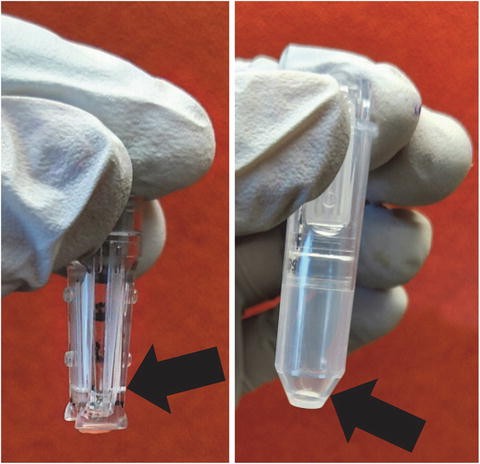
Example of the ideal final volume in the micron filter after the final centrifugation. The picture on the left shows the filter with the final volume; while the picture on the right shows the sample after it has been spun out of the filter into a sterile tube. Arrows highlight the small volume
-
14.
While the DNA is being concentrated, chill the electroporation cuvettes on ice until ready to use.
-
15.
Invert the micron filter into a sterile collecting tube (provided by manufacturer) and spin at ~16,000 × g for 30 s to collect the concentrated DNA.
-
16.
Allow the pir-116 electrocompetent E. coli to thaw on ice about 10 min before starting the electroporation (see Note 20 ). The electrocompetent E. coli should be stored at −80 °C.
-
17.
Add between 30 and 50 μL of the electrocompetent E. coli cells to the well of the cuvette located between the two metal plates (see Note 21 ). Do NOT pipette cells up and down.
-
18.
Add the 10–20 μL of concentrated DNA to the E. coli cells in the cuvette. Flick gently to mix. Keep on ice.
-
19.
Pulse the E. coli cells by using the “bacteria” setting of the electroporation apparatus (we use MicroPulser from Bio-Rad).
-
20.
Pipette 200–300 μL of sterile LB media (or any other rich medium available, e.g., SOC) into the cuvette using a stripette. Mix by pipetting up and down several times. Transfer the entire mixture into a culture tube appropriate for bacterial growth (a round-bottom polystyrene 5 mL tubes).
-
21.
Grow the bacteria at 37 °C in a shaking incubator for 1 h.
-
22.
Spread the full volume of bacteria onto a kanamycin LB agar plate. Incubate at 37 °C for at least 18 h. This pir-116 strain of E. coli cells might require a longer incubation time for colonies to grow to a size detectable by the naked eye.
-
23.
Pick individual bacterial colonies for growth. We usually grow bacteria in 2 mL of kanamycin LB broth for plasmid extraction (miniprep). Shake overnight at 37 °C.
-
24.
Transfer about two-thirds of the 2 mL culture into a 1.5 mL Eppendorf microfuge tube and centrifuge to pellet the bacterial cells (~16,000 × g for 2 min). Discard supernatant. The leftover culture is stored at 4 °C as backup in case more is needed later.
-
25.
Isolate the plasmid DNA following the manufacturer’s protocol.
-
26.
Evaluation of the kanR rescue clones (i.e., plasmids) is performed by a restriction enzyme digestion using a combination of either AatII and AvrII or SfiI and SalI. This digestion will monitor potential contamination and provide a visual representation of different recovered retrotransposition events used to guide selection of which plasmids to sequence (Fig. 5 shows an example).
Fig. 5 
Evaluation of Alu rescue clones by restriction digest. A schematic representation of the expected recovered DNA with the tagged-Alu insert with the circularized flanking sequence is shown. Restriction sites (AatII and AvrII) were selected so that they flank the location of the splice junction to yield a 939 bp fragment. Clones that do not show the 939 bp fragment are likely recovered contaminants of other kanR plasmids. Alu inserts located in different genomic regions will contain different flanking sequences and will generate unique digest patterns depending on presence/absence of the selected restriction sites (REs). In the example shown, clones 2 and 6 are likely duplicates of the same Alu insert, while clones 1, 2, 8, and 9 are likely recovered Alu inserts located at different genomic sites. M = marker. Similar analysis can be performed using SfiI and SalI digests
-
27.
Each selected plasmid is sequenced using three primers: RAluneoj primer, FAtail230 primer, and a primer uniquely designed for the 3′ genomic flank of the Alu insert (see Note 9 ).
-
28.
Once sequences are received, the genomic position of each rescued Alu insertion is determined by BLAT (http://genome.ucsc.edu). In some occasions, an insert lands in a repetitive sequence, which may be very difficult to precisely map.


4 Notes
-
1.
Cell lines: we have been able to perform SINE retrotransposition in both human, rodent cells and in one chicken embryo fibroblast cell line [23]. Our experience is limited to cell lines that form monolayers, but LINE retrotransposition has been described in chicken DT40 suspension cells using soft agarose medium [24]. The human cell lines we primarily use are HeLa, HCT-116, and HEK293. The rodent cell lines we use are BHK, CHO-K1, and CHOUV20. Cell selection is critical, as some cells cannot support retrotransposition [19]. Cells can also exhibit clonal variation with regard to how well they support retrotransposition [20].
-
2.
Supplements for tissue culture media can be obtained from local vendors: fetal bovine serum (FBS ), MEM nonessential amino acids (NEAA) 100×, and sodium pyruvate 100 mM (NaPyr). For antibiotic selection, concentrations vary depending on the cell line. These are the concentrations routinely used in HeLa cells: Geneticin stock of 50 mg/mL active geneticin (4.4 mL stock per 500 mL of medium); Hygromycin B stock in 1× PBS 50 mg/mL (700 μL stock per 500 mL of medium). For prevention against mycoplasma, bacteria, and fungi (optional), the following reagents can be added to the culture media: Normocin (Invivogen), Fungizone, and Penicillin/Streptomycin (Pen/Strep). This is recommended for experiments that take multiple weeks.
-
3.
Tissue culture flasks and plates: we use standard polystyrene vented cap flasks and clear polystyrene flat bottom plates. However, different cell lines may have different requirements such as the need for a surface treatment that enhances cell attachment. Use the materials that are appropriate for the cell line.
-
4.
L1 factors are required to drive Alu retrotransposition events. Therefore, Alu must be co-transfected with a plasmid expressing either the full length L1 or the L1 ORF2 protein as the driver [7]. Several of the plasmids are available in Addgene: http://www.addgene.org/browse/pi/1826/
-
5.
Crystal violet staining solution (0.2 % crystal violet in 5 % acetic acid and 2.5 % isopropanol) is prepared as follows: dissolve and mix 1 g crystal violet, 15 mL isopropanol, 25 mL glacial acetic acid, and purified water to a final volume of 500 mL.
-
6.
Dedicated reagents and materials. Very Important: all materials including the buffers and enzymes should be used exclusively for rescuing Alu inserts and should only come into contact with the dedicated pipettes, pipettors, and tips. This method is highly susceptible to failure due to contamination with other common plasmids present in most laboratories. We recommend finding a lab bench or other dedicated space that is free of exposure from other plasmids, specifically plasmids containing kanamycin resistance. This is a list of dedicated materials: set of pipettors and tips (pipettors can be decontaminated if required); genomic DNA extraction kit with dedicated buffers; 1-mL stripettes; restriction enzymes and buffers (we routinely use EcoRI and HindIII, although any restriction enzyme that is absent within the retrotransposed sequence and can be heat-inactivated will work. We have also successfully used SpeI, BsrGI, NheI, or NdeI); T4 DNA ligase and ligase buffer; sterile water.
-
7.
We use LB broth, Miller powder, and LB agar, Miller powder. To prepare 1 L of LB broth, dissolve 20 g of powder in 800 mL of water; once dissolved adjust volume to 1 L and autoclave. Add kanamycin (final concentration of 50 μg/mL) to the LB broth once it is completely cooled. Keep refrigerated ~4 °C. To prepare 1 L of LB agar, dissolve 35 g of powder in 800 mL of water; once dissolved adjust volume to 1 L and autoclave. Add kanamycin (final concentration of 50 μg/mL) to the LB agar after it has cooled but not solidified (~55–60 °C) to prevent inactivation of the kanamycin. Pour the plates and let them solidify. For long-term storage, keep refrigerated ~4 °C.
-
8.
0.5× Tris–Borate–EDTA (TBE) (45 mM Tris–Borate, 1 mM EDTA). To make a 5× Stock mix and dissolve: 54 g of Tris base, 27.5 g of boric acid, 20 mL of 0.5 M EDTA, pH 8.0, and purified water to a final volume of 1 L. Dilute 1/10 and add ethidium bromide to a final concentration of ~0.2–0.5 μg/mL.
-
9.
Design of the primer to sequence the 3′ genomic flank of the Alu rescue insert: the primer should anneal ~150–200 bases from the predicted insertion site based on the data obtained from the sequence from the 5′ genomic flank. The primer should be evaluated to make sure it does not anneal to a repetitive sequence. In addition, the location of the sequence corresponding to the restriction site used to digest the genomic DNA (e.g., EcoRI) should be noted to avoid designing a primer to a sequence that may not be present in the circularized DNA. For example, if there is an EcoRI site 180 bp downstream from the predicted insertion site a primer that anneals 210 bp downstream will not work as the circularized DNA will not include anything downstream of where the enzyme cut (180 bp).
-
10.
Depending on the total number of transfections and experimental repeats, transfection reagents can be mixed in 24-, 12-, or 6-well plates instead of individual tubes. The DNA transfection parameters given in Table 1 are our recommendations for what concentrations work in our cell lines. However, each laboratory may need to optimize the total amount of DNA and/or transfection reagents for the best results. We have found that a 1:3 ratio of driver to Alu plasmid DNA, respectively, works well for any Alu retrotransposition assay regardless of total amount of DNA transfected.
-
11.
Individual cell lines can be sensitive to the transfection mixture, resulting in premature cell death. Optimization of the incubation time may need to be tailored to certain cell lines. Our observations indicate that an incubation period of 3 h is sufficient and well tolerated by all the cell lines we have evaluated.
-
12.
The time of selection has been chosen arbitrarily, using colony size as the parameter to determine when to stain cells. HeLa cells form colonies that allow for easy visualization and counting after 2 weeks of selection with geneticin . However, cells that grow faster, such as BHK, will require less time for growth under selection. On the other hand, slow growing cells may require longer periods of time. If media becomes turbid due to large numbers of floating dead cells, change the media more frequently.
-
13.
The indicated Lipofectamine–Plus ratios are the most commonly used in our laboratory. However, transfection efficiencies will vary between cell lines and further optimization of transfection conditions may be needed.
-
14.
The concentration of hygromycin B required for effective selection varies between cell lines. Slow growing cells may require longer time of growth under selection to ensure the death of the untransfected cells.
-
15.
The number of recovered inserts per pool is directly proportional to the number of colonies in the pool. We routinely recover between a fourth and a third of the inserts from any given pool. The recovery efficiency can be improved by processing the same pool multiple times with different restriction enzymes when digesting the genomic DNA.
-
16.
Cells may not grow well at very low densities. It might be necessary to reduce the surface area to grow the cells. For example, if only one rescue colony is recovered, it might be necessary to move the colony into a well of a 6-well or 12-well plate.
-
17.
We routinely expand pooled cells in 150 cm2 dishes to obtain a large amount of material that can be used for multiple DNA extractions. However, if less DNA is needed a T75 would suffice.
-
18.
The time and speed for spinning can vary, as long the parameters selected comply within those suggested by the Amicon 50K manufacturer’s protocol.
-
19.
It is imperative not to dry the membrane out. Please refer to Fig. 4 for an example of an appropriate volume of concentrated genomic DNA.
-
20.
Commonly used electrocompetent E. coli strains will not support replication of the R6Kγori. A specific bacterial strain is required: E. coli pir-116 [F − mcrA Δ(mrr-hsdRMS-mcrBC) φ80dlacZΔM15 ΔlacX74 recA1 endA1 araD139 Δ(ara, leu)7697 galU galK λ- rpsL (Str R) nupG pir-116(DHFR)].
-
21.
A regular 1000 μL pipette tip cannot be used for this step because it is too wide to fit into the groove of the cuvette. Longer, thinner pipette tips should be used (see an example http://www.usascientific.com/200ul-extra-long-filtertip.aspx).
-
22.
Rescue Digestions: mix reagents as follows:
-
5 μL rescued plasmid
-
2 μL 10× appropriate buffer (we used the one supplied by manufacturer)
-
0.2 μL SalI + 0.2 μL SfiI or
-
0.2 μL AatII + 0.2 μL AvrII
-
12.6 μL H2O (final volume of 20 μL)
Incubate at 37 °C for 1 h and run on a 1 % agarose gel.
The restriction sites (AatII and AvrII or SalI and SfiI) were selected so that they flank the location of the splice junction to yield a 939 bp or 1413 bp fragment, respectively. Clones that do not show the expected fragment are likely recovered contaminants of other kanR plasmids. Alu inserts located at different genomic regions will have different flanking sequences generating unique digest patterns depending on presence/absence of the selected restriction sites (REs). This will allow for the elimination of duplicates from the same Alu insert and avoiding sequencing the same insert multiple times.
-
References
Freeman JD, Goodchild NL, Mager DL (1994) A modified indicator gene for selection of retrotransposition events in mammalian cells. Biotechniques 17:46, 48-49, 52
Moran JV, Holmes SE, Naas TP et al (1996) High frequency retrotransposition in cultured mammalian cells. Cell 87:917–927
Goodier JL, Zhang L, Vetter MR, Kazazian HH Jr (2007) LINE-1 ORF1 protein localizes in stress granules with other RNA-binding proteins, including components of RNA interference RNA-induced silencing complex. Mol Cell Biol 27:6469–6483
Ostertag EM, Prak ET, DeBerardinis RJ et al (2000) Determination of L1 retrotransposition kinetics in cultured cells. Nucleic Acids Res 28:1418–1423
Xie Y, Rosser JM, Thompson TL et al (2011) Characterization of L1 retrotransposition with high-throughput dual-luciferase assays. Nucleic Acids Res 39:e16. doi:10.1093/nar/gkq1076, gkq1076 [pii]
Esnault C, Casella JF, Heidmann T (2002) A Tetrahymena thermophila ribozyme-based indicator gene to detect transposition of marked retroelements in mammalian cells. Nucleic Acids Res 30:e49
Dewannieux M, Esnault C, Heidmann T (2003) LINE-mediated retrotransposition of marked Alu sequences. Nat Genet 35:41–48
Dewannieux M, Heidmann T (2005) L1-mediated retrotransposition of murine B1 and B2 SINEs recapitulated in cultured cells. J Mol Biol 349:241–247
Kroutter EN, Belancio VP, Wagstaff BJ et al (2009) The RNA polymerase dictates ORF1 requirement and timing of LINE and SINE retrotransposition. PLoS Genet 5:e1000458
Orioli A, Pascali C, Quartararo J et al (2011) Widespread occurrence of non-canonical transcription termination by human RNA polymerase III. Nucleic Acids Res 39:5499–5512. doi:10.1093/nar/gkr074, gkr074 [pii]
Symer DE, Connelly C, Szak ST et al (2002) Human l1 retrotransposition is associated with genetic instability in vivo. Cell 110:327–338
Gilbert N, Lutz-Prigge S, Moran JV (2002) Genomic deletions created upon LINE-1 retrotransposition. Cell 110:315–325
Gilbert N, Lutz S, Morrish TA et al (2005) Multiple fates of L1 retrotransposition intermediates in cultured human cells. Mol Cell Biol 25:7780–7795
Ostertag EM, Kazazian HH Jr (2001) Twin priming: a proposed mechanism for the creation of inversions in l1 retrotransposition. Genome Res 11:2059–2065
Wagstaff BJ, Hedges DJ, Derbes RS et al (2012) Rescuing Alu: recovery of new inserts shows LINE-1 preserves Alu activity through A-tail expansion. PLoS Genet 8:e1002842. doi:10.1371/journal.pgen.1002842, PGENETICS-D-11-02609 [pii]
Stalker DM, Kolter R, Helinski DR (1982) Plasmid R6K DNA replication: I. Complete nucleotide sequence of an autonomously replicating segment. J Mol Biol 161:33–43
Shafferman A, Helinski DR (1983) Structural properties of the beta origin of replication of plasmid R6K. J Biol Chem 258:4083–4090
Wallace NA, Belancio VP, Deininger PL (2008) L1 mobile element expression causes multiple types of toxicity. Gene 419:75–81
Hulme AE, Bogerd HP, Cullen BR et al (2007) Selective inhibition of Alu retrotransposition by APOBEC3G. Gene 390:199–205
Streva VA, Faber ZJ, Deininger PL (2013) LINE-1 and Alu retrotransposition exhibit clonal variation. Mob DNA 4:16. doi:10.1186/1759-8753-4-16, 1759-8753-4-16 [pii]
Roy AM, West NC, Rao A, Adhikari P et al (2000) Upstream flanking sequences and transcription of SINEs. J Mol Biol 302:17–25
Bennett EA, Keller H, Mills RE et al (2008) Active Alu retrotransposons in the human genome. Genome Res 18:1875–1883
Wallace N, Wagstaff BJ, Deininger PL et al (2008) LINE-1 ORF1 protein enhances Alu SINE retrotransposition. Gene 419:1–6
Honda H, Ichiyanagi K, Suzuki J et al (2007) A new system for analyzing LINE retrotransposition in the chicken DT40 cell line widely used for reverse genetics. Gene 395:116–124. doi:10.1016/j.gene.2007.02.017, S0378-1119(07)00103-5 [pii]
Acknowledgement
The protocols detailed here were developed from work supported by grants from the National Institutes of Health (NIH) P20GM103518/P20RR020152 and R01GM079709A to AMR-E.
Author information
Authors and Affiliations
Corresponding author
Editor information
Editors and Affiliations
Rights and permissions
Copyright information
© 2016 Springer Science+Business Media New York
About this protocol
Cite this protocol
Ade, C., Roy-Engel, A.M. (2016). SINE Retrotransposition: Evaluation of Alu Activity and Recovery of De Novo Inserts. In: Garcia-Pérez, J. (eds) Transposons and Retrotransposons. Methods in Molecular Biology, vol 1400. Humana Press, New York, NY. https://doi.org/10.1007/978-1-4939-3372-3_13
Download citation
DOI: https://doi.org/10.1007/978-1-4939-3372-3_13
Published:
Publisher Name: Humana Press, New York, NY
Print ISBN: 978-1-4939-3370-9
Online ISBN: 978-1-4939-3372-3
eBook Packages: Springer Protocols