
Abstract
Plasma sprayed W-based coatings have the potential application as joining interlayers for the plasma-facing components of future fusion reactors. Particularly in the form of tungsten-steel functionally graded materials (FGMs), they would reduce the stress concentration between the W-based plasma-facing armor and steel-based construction. For mechanical integrity, good adhesion is essential. For this, conventional grit blasting treatment of the substrate may not be sufficient. Therefore, alternative treatments capable of reaching significantly higher roughness without damaging the substrate are sought. In this study, the effects of laser texturing on the adhesion of plasma sprayed W and W-steel FGMs on W and steel substrates are investigated. A variety of surface profiles were achieved by controlled laser ablation in several types of patterns. Their geometric features were systematically varied and measured, and the extent of their filling by the coating material was evaluated. On the most promising patterns, coating adhesion tests were performed in shear loading mode and the best performing patterns were identified. Significant improvement over grit-blasted surface was obtained on patterned surfaces with a high effective contact area, promoting mechanical interlocking. On steel substrates, generally higher adhesion was observed, surpassing already the coating cohesive strength; this is attributed to a combination of mechanical interlocking and metallurgical bonding.
Introduction
For the future fusion reactors, tungsten and tungsten-based materials are the main candidates for the armor of so-called plasma-facing components, which will have to withstand high heat and particle fluxes from the hot plasma. Tungsten’s favorable properties include high melting point, good thermal conductivity, high-temperature strength, resistance to sputtering and low thermal expansion (Ref 1). It has several disadvantageous characteristics, too, for example brittleness at lower temperatures, tendency to recrystallize at higher temperatures, difficult machining and low oxidation resistance. Due to its properties, largely different from those of the Cu-based (in ITER, the International Thermonuclear Experimental Reactor) or steel-based (in DEMO, the future demonstration power plant) materials of the cooling structure, joining presents a significant challenge (Ref 2, 3). Various technologies have been and are being explored, including brazing, solid state bonding, either direct or with the use of various interlayers and the incorporation of FGMs (Ref 3). Plasma spraying is among the alternative technologies applicable in this field. Its advantages are summarized in (Ref 4). In the context of this work, two particular characteristics are worth mentioning—a single-step technology able to provide a tungsten layer on a substrate, without the need for further joining, and the ability to form FGMs with easily controlled compositional gradient. It can be applied in two principal modes—either as the final plasma-facing layer, when coated on the support or cooling structure, or as an interlayer between the bulk tungsten armor and the steel structure. In the latter case, the coating would be applied on the bulk tungsten, contain a gradual transition toward steel on the opposite interface, which would then be bonded to bulk steel at a relatively low temperature (Ref 5). In any case, good adhesion of the plasma sprayed layer is of utmost importance.
As this issue is important for all thermal spray coatings, it has received significant attention over the years. It is generally accepted that higher substrate roughness is beneficial for improved adhesion (Ref 6, 7). The most common method of substrate roughening—grit blasting—can be modified for different roughness, which is nevertheless usually of the order of microns (Ref 8, 9). Besides substrate roughening, various bonding interlayers are also being used. For example, in plasma sprayed ceramics-based thermal barrier coatings, Ni alloys are typically used as bondcoats (Ref 10). However, Ni is an undesired element in fusion reactors due to its long decay after activation by neutrons. In Ref 11, Ti and SiC interlayers were used for vacuum plasma sprayed (VPS) tungsten coatings on graphite. Coatings with the Ti interlayer remained soundly bonded even after a thermal exposure test. In Ref 9, the effects of both the substrate roughness and the Ti or W interlayer provided by physical vapor deposition (PVD) were studied. Although these two factors were not completely delineated due to coating cohesion being lower than adhesion, positive effects of the Ti interlayer were identified, namely the ability to form metallurgical bond with both steel and tungsten, and suppression of oxidation at the interface.
Laser surface texturing was shown to be an interesting method for preparation of functional surfaces with different properties, e.g., tribological (Ref 12, 13), hydrophobic (Ref 14, 15) and light absorbing (Ref 14, 16). It has been used in several studies as a substrate preparation aimed at adhesion improvement for plasma sprayed coatings.
In Ref 17, stress issues as well as substrate preparation effects on VPS W coatings on steel were studied, exploring several laser-sculpted profiles with different morphologies and sizes in the 100 μm range. While some provided insufficient mechanical interlocking, others led to stress concentration at the protruding tips, leading to cracking of the coatings; only those with moderate height to width ratio had positive effect on coating adhesion. In Ref 18, the effects of laser texturing, consisting of equidistant holes in the substrate, with a volume similar to that of the sprayed particles, on the adhesion of plasma sprayed Ni-Al coatings on Al alloy substrates were studied. The findings include (a) significantly improved adhesion compared to conventional substrate treatments, (b) incomplete filling of too deep holes, (c) positive effect of increased effective surface area (ratio of actual surface area to that of a planar surface), i.e., higher frequency of the pattern elements. For the latter, a correlation with adhesion was demonstrated for both metallic and ceramic coatings (Ref 19). In a subsequent study (Ref 20), the interaction of powders and surface patterns of different sizes was investigated in detail, focusing on the pattern filling rate and the effects on adhesion. Somewhat contradictory results were obtained. The pattern filling was higher for pattern volumes smaller and larger than the particle volume. Finer particles adapted better to surface roughness; nevertheless, better adhesion was obtained for larger particles. For all particle sizes, higher adhesion was obtained to larger pattern sizes, and all laser patterned surfaces showed higher adhesion than grit-blasted ones. The general recommendation regarding the surface patterns were provided as: pattern volume roughly equal to the sprayed powder average volume, pattern angles above 70° and pattern opening larger than particles diameters. In a most recent study, Kromer et al. also showed the effect of the laser texturing on the thermomechanical fatigue behavior of bondcoatless thermal barrier coatings, by inducing crack deviation above the interface (Ref 21).
In Ref 22, the development of VPS W coatings for prospective application in moderate heat load plasma-facing components (PFCs) of DEMO was presented. In 2 mm thick W coatings on various steel substrates with the use of thin mixed W/steel interlayer, adhesion of 20-22 MPa on grit-blasted surfaces was reported, with failure having occurred within the sprayed layer. Despite using VPS, significant porosity and presence of impurities were observed in the coatings. The mock-ups were able to withstand steady state heat loads up to 2.5 MW/m2 and cycling heat loads of 2 MW/m2. In Ref 23, the adhesion of VPS W/Eurofer FGMs sprayed at different conditions was studied by measuring the energy release rate during 4-point bending of samples with notched coating. The effects of the spraying process on mechanical properties of the substrates were considered, and the highest interface toughness was observed for conditions leading to substrate hardness reduction, while coating thickness and residual stresses also played a role. Fracture observations indicated the occurrence of plastic deformation in layers with significant steel content, and both mechanical interlocking and metallurgical bonding contributing to the adhesion (Ref 24).
The current study is focused on the effects of laser texturing on the adhesion of plasma sprayed W and W-steel FGMs. The work was carried out in three stages, as shown schematically in Fig. 1. In the first stage, the response of tungsten and steel to the laser ablation was explored and a variety of achievable texture patterns were demonstrated. In the second stage, several prospective patterns were selected, their geometrical features were systematically varied and W coatings were sprayed on them. This was followed by examination of the degree of filling and overall quality of the coating/substrate interface. Finally, several most promising patterns were selected for shear adhesion testing, followed by fracture surface observations.

Schematic flowchart of the experiments
Experimental Details
Tungsten (ITER-qualified, manufactured by Plansee, Austria) and AISI 304 stainless steel (Akros, Czechia) were used as substrates. For the stage 2 spraying experiments, substrates of 3 × 25 × 70 mm size with several surface patterns were used. Based on the evaluation in stage 2, prospective patterns were selected for the shear tests. For these, substrates of 5 × 10 × 30 mm size were used, according to Ref 25, where the 5 × 10 mm face was laser textured and coated. For comparison with the laser-treated substrates, grit-blasted ones were also used; grit blasting was done with F16 grit particles of brown fused alumina.
In the first stage, different lasers were tested for the surface texturing: picosecond, nanosecond and continuous. First trials of laser surface texturing (Fig. 2) were performed using nanosecond laser YPL-HP-1-100-500-500 (IPG Photonics, USA), with 500 W maximum power, 107.1 ns pulse duration, 1.01 mJ maximum pulse energy, 66 µm spot diameter and 35 m/s maximum scanning speed under argon atmosphere. Some samples were also processed in continuous mode. As the obtained patterns were not considered optimal for reasons described in the results section, all further experiments from Fig. 3 onwards were carried out with a picosecond laser with a scanning head, using a variety of parameters under argon atmosphere and in air. Shifted laser surface texturing method (sLST) in burst mode (Ref 26) was used. The achieved processing rate of the shifted LST in burst regime was between 0.5 mm2/min (pattern with columns with 100 µm depth, see below) and 0.7 mm2/min (pattern with holes) (Ref 27). The laser was EdgeWave PX25-2-G laser (EdgeWave, Germany) with 532 nm wavelength, 14 W average power, 10 ps pulse duration and maximum pulse energy of 100 µJ. The scan head was intelliSCAN III 14 (SCANLAB, Germany) with f-theta objective with focal length of 255 mm. The laser spot diameter was 28 µm. The pulse repetition frequency used was 1 MHz; pulse energy was 10-12 µJ. Laser beam scanning speed was 2 m/s for random patterns texturing, and 8 m/s for regular patterns texturing and for cleaning. The distance between the laser scanning lines was 10 μm. Varying depth of the pattern was achieved by the number of repetitions of the same scanning scheme. In the first stage, argon atmosphere was used for prevention of oxidation of surface. The produced textures were laser cleaned by 10 μm step raster scanning through the whole textured area (Ref 28). Laser surface cleaning was applied for decontamination of textured surface from fallen particles on non-textured areas. After the cleaning process, no significant oxidation on surface was detected even for samples textured in air. This fact enabled elimination of argon atmosphere for texturing of the samples in the second stage of the experiments.

Examples of the first demonstration profiles prepared by nanosecond and continuous lasers

Examples of advanced demonstration profiles with dimensional measurements: (a), (b) random wavy patterns with increased roughness, (c), (d) columns, (e), (f) circular holes
Spraying was performed with a WSP-H hybrid torch with argon and water as plasma-forming media and 150 kW power. Spraying parameters were selected based on previous optimization studies (Ref 5, 29) and are listed in Table 1. For tungsten coatings, a 5:1 weight mixture of W (63-80 μm, Global Tungsten and Powders, USA) and WC (40-80 μm, Osram, Czechia) powders was used. The addition of WC powder helped to suppress in-flight oxidation through a reducing effect of carbon (Ref 30); through decarburization during flight, WC was completely converted to W. For the FGM coatings, AISI410 (90-140 μm, Flame Spray Technologies, Netherlands) powder was also used. The FGM coatings consisted of three layers with nominal volume composition of 75, 50 and 25% W, starting with 75% W layer on the W substrate. To minimize the oxidation of the metallic coatings, a shrouding chamber flushed with Ar + 7%H2 mixture was used. A small opening allowed for coating deposition, while a slight overpressure of the shrouding gas caused it to flow through the opening counter to the plasma jet, preventing the entrance of ambient air. A combination of sample movement inside the chamber and torch movement in mutually perpendicular axes facilitated coatings with uniform thickness. Compared to the setup described in Ref 29, where the substrates were preheated by the plasma torch, the chamber was modified to preheat the substrates inductively, to avoid surface oxidation by the plasma jet mixed with air. The preheating temperature was set to 400 °C. All the other spraying parameters were the same as mentioned in Ref 5. Typical coating thickness was around 0.8 mm.
Observation and measurement of the laser textured profiles was performed using a KH-7700 (Hirox, Japan) digital microscope and an EVO MA 15 scanning electron microscope (Carl Zeiss SMT, Germany). The latter was also used for observation of the polished cross sections of the coated substrates and fracture surfaces after the shear tests. Energy-dispersive spectrometry (EDS; XFlash 5010, Bruker, Germany) integrated in the SEM was used to obtain information about the element distribution across the interfaces.
The shear load resistance tests were carried out according to EN 15340 standard (Ref 25). These are commonly called adhesion tests, for short, although the failure mode could be adhesive, cohesive, or a mixture of both. A house-made fixture in an Instron 1362 universal testing machine with 8800 series control module (Instron, UK) was used. The crosshead speed was 3 mm/min. This type of test was selected because of its simplicity and because the loading direction—parallel with the coating plane—represents an important stress direction expected in a plasma-facing component under thermal stress (Ref 31). Five samples of each type were tested. The sample sides were manually ground with an F800 grit paper to remove overspray and to obtain a clearer view of the interface.
Results
Stage 1: Exploration of Different Patterning Techniques
Illustrative examples of various surface patterns on tungsten substrates are shown in Fig. 2. The vertical extent of these profiles ranged from 5 to 150 μm. Some of the patterns were discarded because of insufficient roughness (d), significant melting (a-d) or because of featuring too narrow depressions (a-c, e), which would likely not be filled with impinging molten particles. More promising patterns featuring larger openings, higher roughness and absence of extensive melting are shown in Fig. 3. These types of patterns were prepared by the picosecond laser and were selected for more detailed investigations, as described in the next section.
Stage 2: Interfaces Between Coatings and Textured Substrates
Based on the obtained demonstration patterns and the results of studies mentioned in the introduction, the variety of patterns was narrowed down, considering the following criteria:
-
sufficient opening of the depressions to allow filling by the incoming sprayed particles
-
significantly larger vertical dimensions/effective surface area than the grit-blasted surfaces
-
not too steep slopes of the protrusions, to avoid shadowing effect.
The following patterns were chosen: random “wavy” pattern, intrusions in the form of vertical circular holes and “donuts,” protrusions in the form of circular columns (in the latter text, shorter names, i.e., random, holes, columns, donuts, will be used). For each type of pattern, varying geometrical parameters in the vertical and horizontal direction were used, as listed in Table 2. Schematic of the parameters is shown in Fig. 4. The parameters fixed for the laser control were those at the bottom of the patterns. Due to nature of the laser-material interaction, the patterns had vertical slopes about 15°-25°. As consequence, the openings at the top surface were slightly larger and varied with the pattern depth as well. The purpose of varying the depth was to check the effect of two competing factors—on one hand, increased roughness (higher depth) is expected to lead to increased adhesion by providing more surface for the mechanical interlocking; on the other hand, too deep depressions may lead to incomplete filling by the molten particles. Variation of the horizontal parameters (distance of the columns or diameter of the holes) varies the ratio of a planar surface to the patterned one. All of these parameters affect the effective surface where the substrate and coating get in contact. To check a possible effect of the initial surface condition, rough (as-machined) and polished surfaces were used for the laser treatment. Examples of the pattern appearance are shown in Fig. 5.

Schematic (examples) of the geometrical parameters for the “columns” and “holes” patterns. For the columns, the dimensions of the tips at the top surface were kept constant, while their distance (L) was varied. For the holes, distance of their edges at the top surface was kept constant, while their diameter (Dm) was varied

Examples of the patterns used in stage 2 (top view): (a) random, depth 80 (labelled RA in Table 2), (b) columns, depth 80, distance 80 (RC), (c) holes, depth 80, diameter 80 (RF), (d) donut-shaped holes, depth 60 (RH)
Prefix R stands for rough (machined) and P for polished initial surface. Effective surface is a ratio of the patterned surface to a planar surface (estimated only for the regular patterns, i.e., columns, holes and donuts). While the same pattern shapes (RA to RH) were also applied on the polished surfaces, some of them were dismissed from evaluation due to extensive delamination; only those evaluated are listed here.
Figure 6 shows representative cross sections of selected patterns with plasma sprayed W coatings. Although all parameter combinations were documented and evaluated, only few illustrative examples are given here. The observations could be summarized as follows:

Cross sections of selected surface patterns with W coatings: (a) RA—random, depth 100, (b) RC—columns, depth 80, distance 100, (c) RE—holes, depth 100, diameter 60, (d) RH—donuts, depth 100, (e) PH—polished surface, random, depth 100, (f) PH—polished surface, columns, depth 100, distance 100 (all numbers in µm)
-
For all the regular patterns, good filling of the valleys was found (see an enlarged detail in Fig. 7). This indicates having chosen appropriate geometry, i.e., characteristic dimensions of the fabricated surface features comparable or larger than the powder size.
Fig. 7 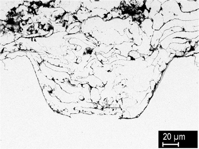
Detail of a depression filled with W coating (RH—donut pattern, depth 100)
-
The inherently occurring slopes did not produce any shadowing effect. Incomplete filling was found only in the deep random pattern (RA, Fig. 6e), in case of too steep valleys.
-
On the samples with polished original surface, delamination was observed regularly, often starting from the untreated smooth surface, therefore not all patterns were evaluated.
-
On the rough surface with random pattern (RA, Fig. 6a), delamination occurred in all three depth variants; in these cases, the pattern depth was significantly lower than nominal and also lower than on the initially polished surface. This indicates that the initial surface state affects the material response to laser ablation.
-
The rough samples with holes (RE, RF, RG, Fig. 6c), all three depths) and with donuts (RH) showed continuous contact along the interface for all geometric variants.
-
On the rough samples with columns (RB, RC, RD, Fig. 6b), delaminations were often observed; however, there was no clear correlation with the pattern geometry; it could possibly be a consequence of local overheating. In this context, it is worth noting that the spraying parameters—particularly deposition temperature and spraying distance—were optimized for high density coatings (Ref 5, 29). The same spraying conditions, favoring good intersplat bonding, also lead to increased levels of residual stress (Ref 32, 33), which may promote debonding.
-
Fine microcracks were observed near the original substrate surface (in the pattern tips, Fig. 6b, c and d).

The microcracks may potentially act as failure initiation sites; therefore, further investigation on their origins was carried out. Figure 8 shows the original machined surface (a) and the (untreated) tip of the column after the laser ablation (b), both containing fine cracks perpendicular to the surface. Based on a visual comparison, it was concluded that the microcracks originated from the machining and not the laser treatment or spraying. Two alternative surface preparations were considered—EDM cutting and grit blasting. Figure 9 shows the respective surfaces. In the EDM-cut tungsten, fine microcracks are also visible. On the grit-blasted surface, higher roughness is achieved and no cracks are apparent. Therefore, this surface treatment was used prior to laser texturing for the shear test samples described in the next section.

(a) Original machined surface of tungsten, (b) tip of the column after the laser ablation, with the top surface untreated

Surfaces of tungsten substrates after (a) EDM cutting, (b) grit blasting
Stage 3: Shear Testing and Fracture Observations
Based on the observations in stage 2, prospective patterns selected were selected for further testing. Specifically, the patterns with absent or minimal coating delamination, good pattern filling and high effective surface were chosen. Additional modification was applied to the geometric parameters to further increase the effective surface. The width of the column tips and the distance between the holes were reduced to 20 μm, to reduce the fraction of untreated surface in favor of the textured one. Since the filling of the valleys was generally good, their width at the bottom was reduced to 30 μm. (Since the bottoms had rounded edges and the valleys were widening toward the surface, this created enough space for the particles to fill.) The effective surface was thereby increased to ~ 2.21 and ~ 2.47 for the columns and holes patterns, respectively. Additionally, one pattern of holes was formed with ~ 45° slope, to see whether such geometry, with the presence of an “overhang,” would increase the anchoring effect. The patterns chosen for the shear testing are summarized in Table 3.
In the following, the sample designation consists of a letter (W or S representing the tungsten or steel substrate, respectively, F representing the FGM coating on a W substrate), followed by the pattern number.
The pattern elements were arranged in a hexagonal array (see Fig. 10a and c), in order to provide equal distance between the nearest neighbors. The same patterns were applied on tungsten and steel substrates. Grit-blasted surfaces were also used for comparison. On these, typical roughness values were Ra = 3-4 μm for W, 8.3-8.9 μm for steel.

Surface patterns on the W samples for the shear tests: (a) random (no. 1), (b) sloped holes (no. 5), (c) columns (no. 4), top view, (d) columns, 45° view
Examples of these patterns prepared on W and steel substrates are shown in Fig. 10 and 11, respectively. It can be seen that for the same geometrical parameters, these two materials slightly differ in their response to laser texturing. The steel substrates show somewhat higher roughness on a microscopic level, in some cases also signs of localized melting (Fig. 11c, d, e and f). This might be caused by the steel’s lower thermal conductivity. Also, the slightly higher roughness of the grit-blasted steel initial surface may have played a role. For the shear testing, the axes of the holes in pattern no. 5 were oriented horizontally, i.e., perpendicular to the loading direction.

Surface patterns on the steel samples for the shear tests: (a) random (no. 2), top view, (b) random (no. 2), 45° view, (c) holes (no. 3), top view, (d) holes, detail, (e) holes, 45° view, (f) sloped holes (no. 5)
Results of the shear load resistance test on tungsten and tungsten-steel FGM coatings on tungsten substrates are summarized in Fig. 12. Samples with random patterns no. 1 and 2 have shear strength comparable to the grit-blasted surface, all in the range of 10-15 MPa. Samples with regular patterns no. 3-5 have higher shear strength, in the range of 20-35 MPa, while the best result was achieved for pattern no. 4 (columns with 100 μm depth). It is assumed that higher effective surface contributes to these higher values. Although pattern no. 4 had slightly lower effective surface than patterns 3 and 5 (cf. Table 3), the shape of the pattern might have played a role. While the basic geometric parameters were the same, the pattern with columns had higher volume (filled with the coating) below the top surface—78 versus 29% for the pattern with holes. This could possibly contribute to stronger mechanical interlocking. For the random patterns, the effective surface was not evaluated due to their random nature; the lower adhesion values are attributed to the incomplete filling of the valleys. Slightly higher values were found for the deeper pattern, as could be expected from a larger contact area available for interlocking.

Shear strength of coatings on tungsten substrates. W1–W5 are W coatings on substrates with surface patterns as numbered in Table 3, WG corresponds to grit-blasted surface, F5 represents the 3-layer FGM on W substrate with pattern no. 5. Sample W4 failed in a mixed cohesive/adhesive mode, all others in an adhesive mode
For all sample sets except W4, the failure occurred at the coating-substrate interface (mode 1 according to the standard, i.e., adhesive failure), indicating that the coating cohesion is higher than the adhesion. For the sample set W4, having the highest shear strength, the failure mode was a mixture of cohesive and adhesive (mode 2). Therefore, for this substrate profile, the adhesion and cohesion are comparable.
The FGM coating deposited on tungsten with pattern no. 5 showed the lowest shear strength, even lower than pure W coating on the grit-blasted surface. The failure mode was again adhesive. In FGM coatings in general, a gradient of residual stresses is inevitably present due to gradient in properties (Ref 32), resulting in bending moment acting on the coating and normal stress component at the interface. These may have further contributed to the reduced adhesion.
Results of the shear load resistance test on steel substrates are summarized in Fig. 13. Generally higher shear strengths than on the tungsten substrates, in the range of 30-40 MPa, are observed. The failure mode was cohesive in all cases, while the coating chipped off in one piece (mode 3b). The measured values are therefore indicative of the coating’s cohesive strength. Since the adhesion was higher in all cases, the particular variations of the surface pattern did not have any strong effect, although slightly higher values were found for the laser-treated surfaces than for the grit-blasted ones. Higher adhesion of tungsten coatings on steel substrates than on W substrates was expected, in view of the conclusions of Ref 9, as will be further discussed below.

Shear strength of coatings on steel substrates. S1–S5 are W coatings on steel substrates with surface patterns as numbered in Table 3, SG corresponds to grit-blasted surface. All the samples failed in a cohesive mode
The values presented in Fig. 13 are higher or comparable to those obtained for atmospheric plasma sprayed W coatings on grit-blasted steel substrates with or without PVD interlayers (15-45 MPa, same type of test) (Ref 9) and also higher than adhesion of vacuum plasma sprayed W coatings with mixed W-steel interlayer (20-22 MPa, test type not specified) (Ref 22). When compared to bulk materials joints, the present values are slightly higher than those of explosively welded W-CuCrZr joints (~ 33 MPa, tensile test) (Ref 34), but significantly lower than those of SPS diffusion-bonded W-steel (160-220 MPa, shear test) (Ref 35) or brazed W-steel with Ni interlayer (~ 100 MPa, shear test) (Ref 36). Such differences could be expected due to the structure of plasma sprayed layers, containing pores and imperfectly bonded interfaces.
SEM observations of the fractured samples revealed more details about the splat-substrate interaction upon impact and their behavior during the shear tests. Figure 14 shows the fracture surfaces of a sample from the W2 set. Majority of the original laser-treated substrate surface is revealed, with only isolated remnants of the coatings. Figure 14b) shows that even very narrow valleys were filled with the molten W of the coatings; however, in the absence of a metallurgical bond, the strength of this bond is rather low, as testified by the incipient delamination along the remnants of the splat. Similar situation occurred in samples with FGM coating (set F5)—failure took place primarily along the interface, revealing most of the substrate (Fig. 15a) with only few small coating remnants in the holes, despite very good filling by the coating, as testified in Fig. 15(b). Rather good reproduction of the substrate profile can be seen, although with a certain level of porosity in the coating. In contrast, for the samples of the W4 set, the fracture occurred primarily within the coating, by a combination of intersplat decohesion and intrasplat cracking (Fig. 16).

Fracture surfaces of sample W2 (W coating, W substrate, random pattern with 60 μm depth): (a) overview, (b) detail of valleys filled with W splat. Fractured splat shows characteristic columnar structure, resulting from directional heat transfer

Fracture surfaces of sample F5 (FGM, W substrate, sloped holes): (a) revealed substrate, (b) coating counterpart (bottom view)

Fracture surfaces of sample W4 (W coating, W substrate, columns with 100 μm depth): (a) overview, (b) detail of a fracture within the coating
In the W coatings on steel substrates, the fracture took place also within the coatings; a combination of splat cracking and decohesion is shown in Fig. 17. Additionally, Fig. 18 shows the cross section of a fractured sample from the same set (S2, random pattern, 60 µm depth). Since the steel substrate reacted differently to the laser treatment compared to W substrates, the valleys are somewhat steeper (cf. Fig. 11a and b), resulting in limited filling by the W splats. Still, the molten material was able to penetrate into rather narrow passages, as can be seen in Fig. 18(a). Signs of material mixing and interdiffusion, particularly near the pattern tips, are frequently seen (several locations in Fig. 18a, magnified detail in Fig. 18b, center). This was further demonstrated by EDS line scans—Fig. 18(c) shows a line scan through the region of intense mixing, spanning some 10-15 μm (Fig. 18d, enlarged center of Fig. 18b); Fig. 18(e) shows a line scan across an apparently sharp interface (Fig. 18f). These results indicate the presence of a metallurgical bond, promoted by the so-called incipient melting (Ref 9, 37). As the impinging molten W particles cause localized melting of steel substrate in a thin layer, this promotes tight contact between the two materials, their mixing and interdiffusion. Thus, in the tungsten coatings on steel substrates, higher adhesion strength is attributed to the combination of metallurgical bond and mechanical interlocking. Both the mechanical interlocking and metallurgical bond may have been also promoted by the increased micro-roughness compared to tungsten substrates (cf. Fig. 10 and 11). As the extent of material mixing varied from point to point, the relative contribution of these two phenomena is difficult to estimate. The abovementioned mechanism is not expected not operate in the W–W coating-substrate combination. A cross section through a sample from the S5 set (sloped holes, 100 µm depth) is shown in Fig. 19. It reveals again a good filling of the valleys—even regions not directly in line of the plasma torch’s sight, Fig. 19(a) and (b)—and regions with noticeable material mixing and interdiffusion, left side of Fig. 19(b).

Fracture surfaces of sample S2 (W coating, steel substrate, random pattern with 60 μm depth): (a) overview (with a trace of cutting by the shearing plate in the middle), (b) detail of a fracture within the coating

Cross section of an S2 sample after the shear test: (a) overview, (b) detail of the coating-substrate interface showing intense mixing of molten and resolidified materials, accompanied by interdiffusion (backscattered electron images), (c) EDS line scan across the region of intense mixing (d), (e) EDS line scan across a sharp interface (f)

Cross section of an S5 sample (sloped holes, 100 µm depth) after the shear test: (a) overview, (b) detail (backscattered electron images). The sections in this and previous figure were made in an oblique angle with respect to the substrate pattern, in order to cross the pattern elements in various locations. Therefore, the section does not reflect all the geometrical features of the pattern the same way as in parallel positioning
Conclusions
In this work, the effect of laser texturing on the adhesion of plasma sprayed coatings on W and steel substrates was studied. The main purpose was to increase the substrate roughness, thus increasing the effective contact area, in a controlled manner that would promote proper filling and intimate contact. Several patterns formed by laser texturing were formed and analyzed; for those with suitable size, i.e., opening comparable to the size of the sprayed particles, good filling by the coating material was observed. For W coatings on W substrates, comparable or higher adhesion was achieved on the laser-treated substrates than on grit-blasted ones. For the best performing combination—protruding columns of 100 μm height and 20 μm tip width, shear strength about 33 MPa—the failure mode was predominantly cohesive, i.e., the adhesion strength exceeded the coating strength. In all other cases, the main failure mode was adhesive, i.e., debonding at the coating-substrate interface. The improvement in adhesion is attributed to significantly increased effective surface with suitable geometrical parameters, leading to improved mechanical interlocking. The 3-layer FGM featured the lowest strength, with possible contribution from residual stress gradient stemming from the material gradation. The coatings sprayed on steel substrates featured generally higher strength than those sprayed on W substrates. The shear strength was in the 30-40 MPa range, comparable to the best value achieved on W substrate. Particular types of surface patterns did not have observable effect, as the adhesion strength was higher than cohesive strength of the coatings. Localized substrate melting, accompanied by intermixing of coating and substrate species, leading to tighter contact and localized metallurgical bonding, are proposed as mechanisms responsible for the adhesion improvement. As the highest obtained shear strength values correspond to cohesive failure, further improvement can be achieved only by improving the coating’s strength.
Better adhesion of the tungsten coatings on steel substrates than on tungsten ones may have consequences for prospective PFC fabrication routes involving plasma sprayed layers. Solely from the adhesion point of view, the more promising route appears to be spraying W coatings as the plasma-facing layer on steel substrates, rather than spraying W on W substrates, as the first layer of W-steel FGM, with subsequent bonding of the steel end to bulk steel. Nevertheless, besides adhesion, other factors are important for the intended application, such as thermal conductivity, thermal shock and thermal fatigue resistance, hydrogen retention, etc. In order to be applicable as the plasma-facing layer, the coatings should be optimized in these directions.
References
G. Pintsuk, Tungsten as a Plasma-Facing Material, Comprehensive Nuclear Materials, R.J.M. Konings, Ed., Elsevier, New York, 2012,
T. Weber, M. Stueber, S. Ulrich, R. Vassen, W.W. Basuki, J. Lohmiller, W. Sittel, and J. Aktaa, Functionally Graded Vacuum Plasma Sprayed and Magnetron Sputtered Tungsten/Eurofer97 Interlayers for Joints in Helium-Cooled Divertor Components, J. Nucl. Mater., 2013, 436(1-3), p 29-39
S. Heuer, J.W. Coenen, G. Pintsuk, J. Matějíček, M. Vilémová, and Ch. Linsmeier, Overview of Challenges and Developments in Joining Tungsten and Steel for Future Fusion Reactors, Phys. Scr., 2019, in press
J. Matějíček, P. Chráska, and J. Linke, Thermal Spray Coatings for Fusion Applications—Review, J. Therm. Spray Technol., 2007, 16(1), p 64-83
S. Heuer, J. Matějíček, M. Vilémová, M. Koller, K. Illková, J. Veverka, T. Weber, G. Pintsuk, J.W. Coenen, and C. Linsmeier, Atmospheric Plasma Spraying of Functionally Graded Steel/Tungsten Layers for the First Wall of Future Fusion Reactors, Surf. Coat. Technol., 2019, 366, p 170-178
M. Mellali, P. Fauchais, and A. Grimaud, Influence of Substrate Roughness and Temperature on the Adhesion/Cohesion of Alumina Coatings, Surf. Coat. Technol., 1996, 81(2-3), p 275-286
Y.Y. Wang, C.J. Li, and A. Ohmori, Influence of Substrate Roughness on the Bonding Mechanisms of High Velocity Oxy-Fuel Sprayed Coatings, Thin Solid Films, 2005, 485(1-2), p 141-147
M. Vilémová, J. Siegl, J. Matějíček, and R. Mušálek, Effect of the Grit Blasting Exposure Time on the Adhesion of Al2O3 and 316L Coatings, Proceedings of International Thermal Spray Conference, Hamburg, DVS-German Welding Society, 2011, p 1001-1006
J. Matějíček, M. Vilémová, R. Mušálek, P. Sachr, and J. Horník, The Influence of Interface Characteristics on the Adhesion/Cohesion of Plasma Sprayed Tungsten Coatings, Coatings, 2013, 3, p 108-125
W. Nowak, D. Naumenko, G. Mor, F. Mor, D.E. Mack, R. Vassen, L. Singheiser, and W.J. Quadakkers, Effect of Processing Parameters on MCrAlY Bondcoat Roughness and Lifetime of APS-TBC Systems, Surf. Coat. Technol., 2014, 260, p 82-89
G.S. Cho and K.H. Choe, Characterization of Plasma-Sprayed Tungsten Coating on Graphite With Intermediate Layers, Surf. Coat. Technol., 2012, 209, p 131-136
D. Braun, C. Greiner, J. Schneider, and P. Gumbsch, Efficiency of Laser Surface Texturing in the Reduction of Friction Under Mixed Lubrication, Tribol. Int., 2014, 77, p 142-147
S. Houdkova, P. Sperka, M. Repka, J. Martan, and D. Moskal, Shifted Laser Surface Texturing for Bearings Applications, J. Phys. Conf. Ser., 2017, 843, p 012076
A.Y. Vorobyev and C.L. Guo, Multifunctional Surfaces Produced by Femtosecond Laser Pulses, J. Appl. Phys., 2015, 117(3), p 033103
J.T. Cardoso, A.I. Aguilar-Morales, S. Alamri, D. Huerta-Murillo, F. Cordovilla, A.F. Lasagni, and J.L. Ocana, Superhydrophobicity on Hierarchical Periodic Surface Structures Fabricated via Direct Laser Writing and Direct Laser Interference Patterning on an Aluminium Alloy, Opt. Lasers Eng., 2018, 111, p 193-200
J. Yang, F.F. Luo, T.S. Kao, X. Li, G.W. Ho, J.H. Teng, X.G. Luo, and M.H. Hong, Design and Fabrication of Broadband Ultralow Reflectivity Black Si Surfaces by Laser Micro/Nanoprocessing, Light Sci. Appl., 2014, 3, p e185
G. Thomas, R. Vincent, G. Matthews, B. Dance, and P.S. Grant, Interface Topography and Residual Stress Distributions in W Coatings for Fusion Armour Applications, Mater. Sci. Eng. A, 2008, 477(1-2), p 35-42
R. Kromer, S. Costil, J. Cormier, D. Courapied, L. Berthe, P. Peyre, and M. Boustie, Laser Surface Patterning to Enhance Adhesion of Plasma Sprayed Coatings, Surf. Coat. Technol., 2015, 278, p 171-182
R. Kromer, J. Cormier, and S. Costil, Role of Powder Granulometry and Substrate Topography in Adhesion Strength of Thermal Spray Coatings, J. Therm. Spray Technol., 2016, 25(5), p 933-945
R. Kromer, S. Costil, J. Cormier, L. Berthe, P. Peyre, and D. Courapied, Laser Patterning Pretreatment Before Thermal Spraying: A Technique to Adapt and Control the Surface Topography to Thermomechanical Loading and Materials, J. Therm. Spray Technol., 2016, 25(3), p 401-410
R. Kromer, F. Mauget, L. Despres, S. Costil, and J. Cormier, Thermo-mechanical Fatigue Evaluation of a Thermal Barrier Coating Bond-Coatless System, Mater. Sci. Eng. A, 2019, 756, p 130-141
H. Greuner, H. Bolt, B. Boswirth, S. Lindig, W. Kuhnlein, T. Huber, K. Sato, and S. Suzuki, Vacuum Plasma-Sprayed Tungsten on Eurofer and 316L: Results of Characterisation and Thermal Loading Tests, Fusion Eng. Des., 2005, 75-79, p 333-338
T. Emmerich, D.D. Qu, R. Vassen, and J. Aktaa, Development of W-Coating With Functionally Graded W/Eurofer-Layers for Protection of First-Wall Materials, Fusion Eng. Des., 2018, 128, p 58-67
D. Qu, E. Gaganidze, R. Vassen, and J. Aktaa, Determination of Interface Toughness of Functionally Graded Tungsten/Eurofer Multilayer at 550 Degrees C by Analytical and Experimental Methods, Eng. Fract. Mech., 2018, 202, p 487-499
EN 15340, Thermal Spraying—Determination of Shear Load Resistance of Thermally Sprayed Coatings, European Committee for Standardization, Brussels, 2007
J. Martan, D. Moskal, and M. Kucera, Laser Surface Texturing with Shifted Method: Functional Surfaces at High Speed, J. Laser Appl., 2019, 31(2), p 022507
D. Moskal, J. Martan, and M. Kučera, Shifted Laser Surface Texturing (sLST) in Burst Regime, Proceedings of the 19th International Symposium on Laser Precision Microfabrication, (Edinburgh), Association of Industrial Laser Users (AILU) at Heriot-Watt University, 2018, p OR7
D. Moskal, J. Martan, M. Kucera, S. Houdkova, and R. Kromer, Picosecond Laser Surface Cleaning of AM1 Superalloy, Phys. Procedia, 2016, 83, p 249-257
J. Matějíček, M. Vilémová, B. Nevrlá, L. Kocmanová, J. Veverka, M. Halasová, and H. Hadraba, The Influence of Substrate Temperature and Spraying Distance on the Properties of Plasma Sprayed Tungsten and Steel Coatings Deposited in a Shrouding Chamber, Surf. Coat. Technol., 2017, 318, p 217-223
J. Matějíček, V. Weinzettl, E. Dufková, V. Piffl, and V. Peřina, Plasma Sprayed Tungsten-Based Coatings and Their Usage in Edge Plasma Region of Tokamaks, Acta Tech. CSAV, 2006, 51(2), p 179-191
S. Heuer, T. Weber, G. Pintsuk, J.W. Coenen, J. Matejicek, and C. Linsmeier, Aiming at Understanding Thermo-mechanical Loads in the First Wall of DEMO: Stress–Strain Evolution in a Eurofer–Tungsten Test Component Featuring a Functionally Graded Interlayer, Fusion Eng. Des., 2018, 135, p 141-153
J. Matějíček, R. Mušálek, and J. Veverka, Materials and Processing Factors Influencing Stress Evolution and Mechanical Properties of Plasma Sprayed Coatings, Surf. Coat. Technol., 2019, 366, p 170-178
J. Matejicek, S. Sampath, D. Gilmore, and R. Neiser, In Situ Measurement of Residual Stresses and Elastic Moduli in Thermal Sprayed Coatings—Part 2: Processing Effects on Properties of Mo Coatings, Acta Mater., 2003, 51(3), p 873-885
C.X. Sun, S.M. Wang, W.H. Guo, W.P. Shen, and C.C. Ge, Bonding Interface of W-CuCrZr Explosively Welded Composite Plates for Plasma Facing Components, J. Mater. Sci. Technol., 2014, 30(12), p 1230-1234
W.Q. Kong, X.F. Li, B.Y. Chen, C.Y. Wang, H.J. Chu, Y.T. Chen, P. Hua, and W. Zhou, Microstructure and Mechanical Properties of Diffusion Bonded W/MA956 Steel Joints With a Titanium Interlayer by SPS, J. Adhes. Sci. Technol., 2019, 33(17), p 1847-1857
W. Krauss, J. Lorenz, J. Konys, W. Basuki, and J. Aktaa, Thermomechanical Characterization of Joints for Blanket and Divertor Application Processed by Electrochemical Plating, Fusion Eng. Des., 2016, 109, p 1280-1285
S. Dallaire, Influence of Temperature on the Bonding Mechanism of Plasma-Sprayed Coatings, Thin Solid Films, 1982, 95(3), p 237-244
Acknowledgments
This work has been carried out within the framework of the EUROfusion Consortium and has received funding from the Euratom Research and Training Programme 2014-2018 under Grant Agreement No 633053. Support by Czech Science Foundation (Grant No. GA17-23154S), by the Czech Academy of Sciences (Strategy AV21 programme) and by the Ministry of Education, Youth and Sports of the Czech Republic (OP RDI Program, CENTEM Project, No. CZ.1.05/2.1.00/03.0088, co-funded by the ERDF; ITI II Program, LABIR-PAV Project, No. CZ.02.1.01/0.0/0.0/18_069/0010018) is also acknowledged.
Author information
Authors and Affiliations
Corresponding author
Additional information
Publisher's Note
Springer Nature remains neutral with regard to jurisdictional claims in published maps and institutional affiliations.
Rights and permissions
About this article

Cite this article
Matějíček, J., Vilémová, M., Moskal, D. et al. The Role of Laser Texturing in Improving the Adhesion of Plasma Sprayed Tungsten Coatings. J Therm Spray Tech 28, 1346–1362 (2019). https://doi.org/10.1007/s11666-019-00924-7
Received:
Revised:
Published:
Issue Date:
DOI: https://doi.org/10.1007/s11666-019-00924-7