
Abstract
Spectral unmixing is one of the most popular techniques to analyze remotely sensed hyperspectral images. It generally comprises three stages: (1) reduction of the dimensionality of the original image to a proper subspace; (2) automatic identification of pure spectral signatures (called endmembers); and (3) estimation of the fractional abundance of each endmember in each pixel of the scene. The spectral unmixing process allows sub-pixel analysis of hyperspectral images, but can be computationally expensive due to the high dimensionality of the data. In this paper, we develop the first real-time implementation of a full spectral unmixing chain in commodity graphics processing units (GPUs). These hardware accelerators offer a source of computational power that is very appealing in hyperspectral remote sensing applications, mainly due to their low cost and adaptivity to on-board processing scenarios. The implementation has been developed using the compute device unified architecture (CUDA) and tested on an NVidia™ GTX 580 GPU, achieving real-time unmixing performance in two different case studies: (1) characterization of thermal hot spots in hyperspectral images collected by NASA’s Airborne Visible Infra-red Imaging Spectrometer (AVIRIS) during the terrorist attack to the World Trade Center complex in New York City, and (2) sub-pixel mapping of minerals in AVIRIS hyperspectral data collected over the Cuprite mining district in Nevada.
1 Introduction
Hyperspectral imaging instruments are capable of collecting hundreds of images, corresponding to different wavelength channels, for the same area on the surface of the Earth [1]. For instance, NASA is continuously gathering imagery data with instruments such as the Jet Propulsion Laboratory’s Airborne Visible-Infrared Imaging Spectrometer (AVIRIS), which is able to record the visible and near-infrared spectrum (wavelength region from 0.4 to 2.5 μm) of reflected light in an area 2–12 km wide and several kilometers long, using 224 spectral bands [2]. The resulting multidimensional data cube typically comprises several GBs per flight (see Fig. 1). The wealth of spectral information provided by latest-generation hyperspectral imaging instruments has opened ground-breaking perspectives in many applications [3], many of which require real-time response of algorithm analysis [4–6].
One of the main problems in the analysis of hyperspectral data cubes is the presence of mixed pixels [7], which arise when the spatial resolution of the sensor is not fine enough to separate spectrally distinct materials. For instance, the pixel vector labeled as “vegetation” in Fig. 1 may actually be a mixed pixel comprising a mixture of vegetation and soil, or different types of soil and vegetation canopies. This is a common scenario in real-world applications, in which the spatial resolution of the sensor cannot separate between spectrally pure components, which may also appear mixed at intimate levels. In this case, several spectrally pure signatures are combined into the same (mixed) pixel and efficient techniques are required to identify the spectral signatures of these pure components and their abundance within hyperspectral image pixels. Hyperspectral unmixing [8, 9] is one of the most popular techniques to analyze hyperspectral data. It generally comprises three stages: (1) reduction of the dimensionality of the original image to a proper subspace, (2) automatic identification of pure spectral signatures (called endmembers), and (3) estimation of the fractional abundance of each endmember in each pixel of the scene. A very recent review work describes extensively the contributions in the area of spectral unmixing in the past years [10]. As mentioned in this paper, the spectral unmixing process can be quite expensive in computational terms, mainly due to the extremely high dimensionality of hyperspectral data cubes [11].

The concept of remotely sensed hyperspectral imaging
Spectral unmixing involves the separation of a pixel spectrum into its pure component endmember spectra and the estimation of the abundance value for each endmember [7]. The linear mixture model assumes that the endmember substances are sitting side-by-side within the field of view of the imaging instrument. On the other hand, the nonlinear mixture model assumes nonlinear interactions between endmember substances. In practice, the linear model is more flexible and can be easily adapted to different analysis scenarios [9]. It can be simply defined as follows:
where \({{\mathbf x}}\) is an \(n\)-dimensional pixel vector given by a collection of values at different wavelengths, \({\mathbf E} =\{ {\mathbf e}_i \}_{i=1}^p\) is a matrix containing \(p\) endmembers, \({\mathbf a} =[a_1,a_2,\ldots ,a_p]\) is a \(p\)-dimensional vector containing the abundance fractions for each of the \(p\) endmembers in \({{\mathbf x}},\) and \({\mathbf n}\) is a noise term. Solving the linear mixture model involves (1) identifying a collection of \(\{{\mathbf e}_i\}_{i=1}^p\) endmembers in the image and (2) estimating their abundance in each pixel. Several techniques have been proposed for such purposes [4], but all of them are quite expensive in computational terms. Although these techniques map nicely to high-performance computing systems such as commodity clusters [9], these systems are difficult to adapt to on-board processing requirements introduced by applications with real-time constraints such as wild-land fire tracking, biological threat detection, monitoring of oil spills, and other types of chemical contamination. In those cases, low-weight integrated components such as commodity graphics processing units (GPUs) are essential to reduce mission payload. In this regard, the emergence of GPUs now offers a tremendous potential to bridge the gap towards real-time analysis of remotely sensed hyperspectral data [13–24].
In this paper, we develop the first real-time implementation of a full spectral unmixing chain for GPUs. The proposed methodology has been implemented using NVidia™’s compute device unified architecture (CUDA) and tested on an NVidia™ GTX 580 GPU using two different hyperspectral images collected by AVIRIS. The remainder of the paper is organized as follows: Section 2 describes the different modules that comprise the considered unmixing chain. Section 3 describes the GPU implementation of these modules. Section 4 presents an experimental evaluation of the proposed implementations in terms of both unmixing accuracy and parallel performance, and Section 5 concludes the paper with some remarks and hints at plausible future research lines.
2 Hyperspectral unmixing chain
The standard hyperspectral unmixing chain is graphically illustrated by a flowchart in Fig. 2. It should be noted that our implementation focuses on the widely used linear mixture model and consists of three main parts: (1) dimensional reduction, (2) selection of pure spectral signatures or endmembers, and (3) estimation of the abundance of each endmember in each pixel of the scene. In this work, the dimensional reduction step is performed using principal component analysis (PCA) [25, 26], a popular tool for feature extraction in different areas including remote sensing. Computing the PCA is an iterative procedure and is thus subject to many dependencies between subsequent iterations. Furthermore, since the PCA transform must respect orthogonality, it also boasts significant intra-iteration dependencies. For the endmember selection part, we rely on the well-known N-FINDR algorithm [27] which is a standard endmember extraction technique in the hyperspectral imaging community. Finally, abundance estimation is carried out using linear spectral unmixing (LSU) due to its simplicity. In the following, we describe the three modules adopted in our hyperspectral unmixing chain implementation: PCA, N-FINDR and LSU.

Standard hyperspectral unmixing chain
2.1 PCA for dimensionality reduction
PCA is a well-known method for dimensionality reduction [26]. It can be computed by performing the eigendecomposition of the covariance matrix of the input data \({{\mathbf X}} = [{{\mathbf x}}_{1} {{\mathbf x}}_{2} \ldots {{\mathbf x}}_{m}]^{\rm T},\) where \(m\) is the total number of pixels, as can be seen in Eq. (2), where \(\Upsigma\) is the covariance matrix of \({{\mathbf X}}, {{\mathbf P}} = [{\mathbf p}_{1} {\mathbf p}_{2} \ldots {\mathbf p}_{n}]\) is an orthogonal matrix whose columns are the eigenvectors of \(\Upsigma,\; n\) is the total number of spectral bands and \(\Uplambda\) is a diagonal matrix containing the eigenvalues of \(\Upsigma{:} \)
The projection of the data \({{\mathbf X}}\) by the eigenvectors \({{\mathbf P}}\) yields the principal components of \({{\mathbf X}}.\) The eigenvalues in \(\Uplambda\) encase the “weight” of each principal component on the resulting data. By choosing only the eigenvectors corresponding to the largest \(d\) eigenvalues, the dimensionality of the data is reduced while preserving the maximum information (variance).
There are several algorithms for computing the eigendecomposition such as the QR algorithm [32], the multiple relatively robust representations algorithm [33], Jacobi–Davidson algorithm [34], or the Arnoldi algorithm [35]. It should be noticed that in the case of dimensionality reduction, only the largest \(d \ll n\) eigenvalues (and corresponding eigenvectors) need to be computed. The power iteration algorithm [31] is a well-known algorithm for computing the largest eigenpair of a matrix. If one defines a random vector \({\tilde{\mathbf{y}}}\) as \({\mathbf y}= {{\mathbf P}} {\tilde{\mathbf{y}}};\) then we have
If the matrix \(\Upsigma \) has a dominant eigenvalue, i.e. \(|\lambda _{1}| > |\lambda _{j}| \ \forall j \ne 1,\) then as \(k \rightarrow \infty \) the term \((\lambda _{j} / \lambda _{1})^{k} \rightarrow 0 \ \forall j \ne 1;\) hence Eq. (3) will converge to the dominant eigenpair as \(k\) increases. Since the magnitude of \(\lambda _{1}^{k}\) also increases with \(k,\) it is necessary to normalize the computed vector each iteration. Eq. (4) shows the power iteration.
Simultaneous iteration [30] simply consists of applying the power iteration algorithm to several eigenvectors simultaneously. While simultaneous iteration (and power iteration) might not be the most computationally efficient eigendecomposition algorithm available, it is very regular and exposes data parallelism, which improves its potential for parallelization in a massively parallel architecture such as a GPU.
Since the power iteration algorithm converges only to the dominant eigenpair, applying it straightforwardly multiple times would lead to the same result; thus the results need to be decorrelated. This is done by subtracting from the data matrix the influence of the larger eigenvectors, which can be accomplished simultaneously for all eigenpairs being computed. If this deflation is done in the original data space \({{\mathbf X}},\) this will lead to an undesirable increase in the dimensionality of the problem, as a new data matrix \({{\mathbf X}}_{i}\) will need to be created for each eigenpair being computed. However, this deflation step can be done in the space of the eigenvectors (the matrix \({{\mathbf P}}\)), which corresponds to multiplying \({{\mathbf P}}\) by a deflation matrix \(\Updelta.\) Since we are subtracting from each eigenvector the influence of the previous, larger eigenvectors, the deflation matrix \(\Updelta \) is upper triangular. Each non-zero element \(\delta _{ij}\) of \(\Updelta \) is then given by Eq. (5).
While the construction of the matrix \(\Updelta \) has some recursiveness, each row is completely independent from another and can be computed in parallel. Experimental results on the tested GPU (see Sect. 4.3) show that the computation of the deflation matrix \(\Updelta \) typically takes <3 % of the computation time of the eigendecomposition procedure. The complete algorithm is presented in Algorithm 1. \(\Upphi \) corresponds to the power iteration, whereas \(\Uppsi \) is the correction caused by the deflation procedure. The function triu() takes the upper triangular portion of the matrix. This is a consequence of the fact that only the projections of the larger eigenvectors are removed from the smaller ones and not vice-versa. Convergence is achieved when the directions of the eigenvectors \({{\mathbf P}}\) remain unchanged from one iteration to the next.

Simultaneous iteration computes the \(d\) largest eigenpairs directly, without the need to reduce the data matrix to simpler forms or compute the remaining smaller eigenpairs.
2.2 N-FINDR for endmember selection

Graphical interpretation of the N-FINDR algorithm in a three-dimensional space
The N-FINDR algorithm [27] is one of the most widely used and successfully applied methods for automatically determining endmembers in hyperspectral image data without using a priori information. This algorithm looks for the set of pixels with the largest possible volume by inflating a simplex inside the data. The procedure begins with a random initial selection of pixels (see Fig. 3a). Every pixel in the image must be evaluated to refine the estimate of endmembers, looking for the set of pixels that maximizes the volume of the simplex defined by the selected endmembers. The mathematical definition of the volume of a simplex formed by a set of endmember candidates is proportional to the determinant of the set augmented by a row of ones. The determinant is only defined in the case where the number of features is \(p-1,\) \(p\) being the number of desired endmembers [9]. Since in hyperspectral data typically \(n \gg p,\) a transformation that reduces the dimensionality of the input data, is required. In this study, the PCA transform described in the previous section has been used for this purpose. The corresponding volume is calculated for every pixel in each endmember position by replacing that endmember and finding the resulting volume. If the replacement results in an increase of volume, the pixel replaces the endmember. This procedure is repeated in iterative fashion until there are no more endmember replacements (see Fig. 3b). The method can be summarized by a step-by-step algorithmic description which is given below in Algorithm 2.

The feature reduction step of Algorithm 2 applies a dimensionality reduction transformation such as the PCA to reduce the dimensionality of the data from \(n\) to \(d=p-1,\) where \(p\) is an input parameter to the algorithm (number of endmembers to be extracted).
In the initialization stage, let \(\{ {\mathbf e}_1^{(0)},{\mathbf e}_2^{(0)},\ldots ,{\mathbf e}_p^{(0)} \}\) be a set of endmembers randomly extracted from the input data.
At iteration \(k \ge 0,\) the volume defined by the current set of endmembers is calculated in volume calculation as follows:
In the replacement phase of Algorithm 2, for each pixel vector \({{\mathbf x}}_j\) in the input hyperspectral data, we recalculate the volume by testing the pixel in all \(p\) endmember positions, i.e., first calculate \(V({\mathbf x} _j,{\mathbf e} _2^{(k)},\ldots ,{\mathbf e} _p^{(k)}),\) then calculate \(V({\mathbf e} _1^{(k)}, {\mathbf x} _j,\ldots, {\mathbf e} _p^{(k)}),\) and so on until \(V({\mathbf e} _1^{(k)},{\mathbf e} _2^{(k)},\ldots,{\mathbf x} _j). \) If none of the \(p\) recalculated volumes is greater than \(V({\mathbf e} _1^{(k)},{\mathbf e} _2^{(k)},\ldots ,{\mathbf e} _p^{(k)}),\) then no endmember is replaced. Otherwise, the combination with maximum volume is retained. Let us assume that the endmember absent in the combination resulting in the maximum volume is denoted by \({\mathbf e}_i^{(k+1)}.\) In this case, a new set of endmembers is produced by letting \({\mathbf e} _i^{(k+1)}={\mathbf x} _j\) and \({\mathbf e} _l^{(k+1)}={\mathbf e} _l^{(k)}\) for \(l \ne i.\) The replacement step is repeated for all the pixel vectors in the input data until all the pixels have been exhausted.
As a final comment, it has been observed that different random initializations of N-FINDR may produce different final solutions. Thus, our N-FINDR algorithm was implemented in iterative fashion, so that each sequential run was initialized with the previous algorithm’s solution. This means that, once a solution has been achieved by the N-FINDR algorithm, another iterative run of the same algorithm is conducted but this time using the previous solution as the initial condition until the algorithm converges to a simplex volume that cannot be further maximized. Note that the initialization of N-FINDR with a solution already derived by the same algorithm has the potential to improve the volume estimation by the algorithm, as the starting condition is already a good approximate solution that can be refined in iterative fashion by focusing on optimizing the selection of endmembers at the corners of the data distribution. Our experiments show that, in practice, this approach allows the algorithm to converge in a few iterations only and also to obtain progressively more refined solutions in terms of volume by virtue of the iterative nature of the N-FINDR implementation adopted in this work.
2.3 LSU for abundance estimation
Once the set of endmembers \({\mathbf E} =\{{\mathbf e} _i \}_{i=1}^p\) has been extracted, their correspondent abundance fractions \({\mathbf a} =[a_1,a_2,\ldots ,a_p]\) in a specific pixel vector \({\mathbf x} \) of the scene can be simply estimated (in least squares sense) by the following unconstrained expression [8, 9]:
Two physical constraints can be imposed into the model described in (1); these are the abundance non-negativity constraint (ANC), i.e., \(a_i \ge 0\) for all \(1 \le i \le p,\) and the abundance sum-to-one constraint (ASC), i.e., \(\sum\nolimits _{i=1}^{p} a_i = 1.\) It should be noted that the abundance estimation in Eq. (7) does not satisfy the ANC and the ASC constraints. An estimate satisfying the ASC constraint can be obtained by solving the optimization problem:
subject to \(\Updelta = \{ {\hat{\mathbf{a}}}| \sum \nolimits _{{i = 1}}^{p} {\hat{a}_i = 1} \}. \) Similarly, imposing the ANC constraint results in the same optimization problem but subject to \(\Updelta = \{ {\hat{\mathbf a}} | {\hat{a}}_i \ge 0 \hbox{ for all } i\}.\) As indicated in [29], a non-negative constrained least squares algorithm can be used to obtain a solution to the ANC-constrained problem in iterative fashion. Then, imposing the ASC constraint can be achieved by introducing a new endmember signature matrix, denoted by \({\mathbf E} ^{\prime},\) and a modified version of the abundance vector \({\hat{\mathbf{a}}},\) denoted by \({\hat{\mathbf{a}}}^{\prime},\) are introduced as follows:
Although imposing the ASC and ANC constraints represents a common practice in the unmixing literature, these constraints are prone to criticism as the selection of suitable endmembers should lead to abundance estimations that naturally hold such constraints without the need to impose them [9]. In other words, when the ASC and ANC constraints are imposed to estimate the abundances of a set of spectral signatures which are not sufficiently pure or representative, the errors introduced as part of the abundance estimation process can be more critical than those resulting from the use of a linear (instead of a nonlinear) model, or from the selection of inappropriate endmembers. Hence, in this work we do not impose the ANC and ASC constraints and use Eq. (7) for abundance estimation purposes by assuming that the N-FINDR algorithm for endmember extraction will be able to provide good endmember signatures for spectral unmixing purposes in most analysis scenarios.
Although the maximum volume procedure adopted by N-FINDR is successful when pure signatures are present in the data, in some cases there may not be completely pure signatures in a scene. To address this issue, several endmember identification techniques have been developed without assuming the presence of pure signatures in the input data. However, these methods aim at generating virtual endmembers (not necessarily present in the set comprised by input data samples and hence not necessarily associated with realistic spectral constituents). Despite the interest of such techniques [36–39], in this work we focus on the widely used N-FINDR algorithm which provides more realistic spectral signatures as it identifies the endmembers as pixels in the original hyperspectral scene. Further work on implementation of endmember identification and spectral unmixing algorithms without the pure signature assumption will be conducted in future developments.
3 GPU implementation
The architecture of a GPU can be seen as a set of multiprocessors (MPs). Each multiprocessor is characterized by a single instruction multiple data (SIMD) architecture, i.e., in each clock cycle each processor executes the same instruction but operating on multiple data streams. Each processor has access to a local shared memory and also to local cache memories in the multiprocessor, while the multiprocessors have access to the global GPU (device) memory. Unsurprisingly, the programming model for these devices is similar to the architecture lying underneath. GPUs can be abstracted in terms of a stream model, under which all data sets are represented as streams (i.e., ordered data sets). Algorithms are constructed by chaining so-called kernels which operate on entire streams and which are executed by a multiprocessor, taking one or more streams as inputs and producing one or more streams as outputs. Thereby, data-level parallelism is exposed to hardware, and kernels can be concurrently applied without any sort of synchronization. The kernels can perform a kind of batch processing arranged in the form of a grid of blocks, where each block is composed by a group of threads that share data efficiently through the shared local memory and synchronize their execution for coordinating accesses to memory.
With the aforementioned general ideas in mind, our GPU implementation of the hyperspectral unmixing chain comprises three stages: (1) GPU implementation of PCA (called GPU-PCA); (2) GPU implementation of N-FINDR (called GPU-FINDR); and (3) GPU implementation of LSU (called GPU-LSU).
3.1 GPU-PCA
Our GPU version of PCA works as follow: first we load the image data \({\mathbf X} \) from the main memory of the CPU to the global memory of the GPU, where it is centered and normalized to one standard deviation by dividing each data column by its variance before running the PCA algorithm itself. This improves the stability of the subsequent computations.
To perform the data normalization we use a GPU kernel called dataNorm. The invocation of this kernel is configured with as many thread blocks as the number of bands \(n\) of the original image, and maximizing the number of threads per block according to the considered architecture (in our case 1,024 threads per block). The kernel first computes the average value of all the pixels in each band to determine an average pixel \({\bar{\mathbf{X}}},\) and subtracts it from all the pixels in the image. We use shared memory and coalesced accesses to global memory to perform this operation. Figure 4 illustrates the adopted reduction process in graphical form. Afterwards, we subtract this mean pixel from each pixel. Figure 5 shows how this process, called centering, is performed. We can see how the threads of the \(i\)th block compute the \(i\)th band of the mean pixel and then subtract this value from the \(i\)th band of each pixel in the image. In the figure, we denote the last pixel as \(m-1\) and the last thread as \(k-1.\) Because we have less threads than pixels in the image, we process each band in sections of \(k\) threads. At the end of this step we have finished the computation of the operation \({\mathbf X} -{\bar{\mathbf{X}}}.\) The next task to be performed is to add the squares of the centered data in column-wise fashion, using again a reduction method (see Fig. 4). Once this process is completed, we have completed the data normalization process on the whole image \({\mathbf X} \) and the PCA algorithm can now be applied.

Reduction process in shared memory

Centering data scheme in kernel dataNorm
After normalizing the data, the first step in Algorithm 1 is the computation of the covariance matrix \(\Upsigma \) of the normalized image by multiplying the normalized image X by its transpose. This operation can be performed using cuBLAS matrix multiplication. The steps listed below are now repeated until convergence
-
1.
We start building the deflation matrix \(\Updelta \) (line 3 of Algorithm 1). For this first we compute \({\mathbf P}^{\rm T}{\mathbf P} \) in GPU, where \({\mathbf P} \) is a random generated matrix of size \(n\) bands times the numbers of principal components we want to extract \(d-1.\) The computation of \(\Updelta \) can be achieved recursively by adding elements to each row or each columns as we can see in Eq. 5.
-
2.
Then we perform the deflation projection \({\mathbf P} _{\rm dfl} = {\mathbf P} \Updelta \) in GPU using cuBLAS (line 4 of Algorithm 1).
-
3.
In this step we execute the power iteration and the correction caused by the deflation process is calculated. Both matrix–matrix multiplications \(\Upphi = \Upsigma {\mathbf P} _{\rm dfl}\) and \(\Uppsi = {\mathbf P} \hbox{triu}( {\mathbf P} _{\rm dfl}^{\rm T} \Upphi ,-1)\) are performed in GPU using cuBLAS (lines 5 and 6 of Algorithm 1).
-
4.
The computation of \({\mathbf P} = \Upphi - \Uppsi \) (line 7 of Algorithm 1) and \({\mathbf P} = {\mathbf P} / \hbox{norm}({\mathbf P} )\) (line 8 of Algorithm 1) are performed in the CPU as we experimentally observed that their implementation in the GPU did not significantly speed-up the overall computation. It should be noted that P, a \(n\) by \(d\) matrix, has significantly lower dimensionality than \(\Upsigma ,\) a \(n\) by \(n\) matrix, which in turn has a significantly lower dimensionality than the original image X, a \(m\) by \(n\) matrix, since \(m \ll n \ll d.\) This simplifies the memory transfers as the amount of information to be transmitted is significantly smaller than the original data volume.
-
5.
Finally, we analyze convergence by checking if the direction of eigenvectors did not significantly change from the previous iteration. This operation is very simple and can be made again in the CPU. If the measured changes are above a given tolerance threshold we continue iterating; otherwise, we finalize and provide the final eigenvectors.
Once the eigenvectors P have been calculated the final step is to multiply them by the original data X to obtain the dimensionally reduced image. This matrix multiplication operation is again performed in the GPU using the cuBLAS library and specifically the cublasSgemm function.
3.2 GPU-NFINDR
Prior to the implementation of the N-FINDR algorithm on the GPU, a set of optimizations was performed. The most time-consuming computation in the N-FINDR algorithm is the calculation of the determinants. The determinant of a nonsingular matrix \({\mathbf V}\) is usually obtained from the factorization \({\mathbf P} {\mathbf V} ={{\mathbf L}} {{\mathbf U}}\) (where \({\mathbf P} \) is a permutation matrix, \({{\mathbf L}}\) is a unit lower triangular matrix, and \({{\mathbf U}}\) is an upper triangular matrix) as the product of the diagonal elements of \({{\mathbf U}}.\) This decomposition is known as Gaussian elimination or LU factorization (with partial row pivoting). The repeated volume calculations of the N-FINDR algorithm can be reduced by exploiting some basic properties of the LU factorization and matrix determinants. Consider, e.g., the \(p \times p\) and \(p \times p-1\) matrices:
obtained after the feature reduction resulting from the PCA transform. Assume that we have computed the LU factorization (with partial pivoting) \({\mathbf P} _{\mathbf M} {\bar{V}}_{\mathbf M} ^{(1)} = {\mathbf L} _{\mathbf M} {\mathbf U} _{\mathbf M}. \) Then, the LU factorization (with partial pivoting) of \(V_{\mathbf M} ^{(1)}\) is simply given by \({\mathbf P} _{\mathbf M} V_{\mathbf M} ^{(1)} = [{\mathbf U} _{\mathbf M} (L_{M}^{-1} P_{M}^{\rm T} {\mathbf x} _j)].\) Therefore, the LU factorizations required in the volume calculations of the N-FINDR algorithm can be all computed by simply forming the \(p \times m\) matrix \({\hat{\mathbf{M}}} = \left[ \begin{array}{c} 1\, 1\, \ldots \,1\\ {\bar{\mathbf{M}}}^{\rm T} \end{array} \right],\) where \({\bar{\mathbf{M}}}^{\rm T} = {\tilde{\mathbf{M}}}^{\rm T}V, \; \tilde{{\mathbf M} }^{\rm T}=({\mathbf M} ^{\rm T}-\text{ mean}({\mathbf M} ^{\rm T}))/\sqrt{m-1},\) and \(m\) denotes the total number of pixels in the hyperspectral image. Then, we need to compute \({\mathbf L} _{\mathbf M} ^{-1}{\mathbf P} _{\mathbf M} ^{\rm T}{\hat{\mathbf{M}}}.\) This is one of the parts that we accomplished in the GPU by means of a VolumeCalculation kernel which obtains the volume of each pixel for one iteration. The \(m\) volumes required in the first iteration of the N-FINDR algorithm are obtained from the product of the determinant of \({\mathbf U} _{\mathbf M} \) times each one of the entries in the last row of \({\mathbf L} _{\mathbf M} ^{-1}{\mathbf P} _{\mathbf M} ^{\rm T} {\hat{\mathbf{M}}}.\) By means of a ReductionVol kernel, we get the value of the maximum volume and the coordinates of the pixel that produces such volume. Given that \(m \gg p,\) this implies a significant reduction of the computational complexity of the original algorithm. In the following, we describe in step-by-step fashion how lines 2–6 of Algorithm 2 have been implemented in the GPU (the feature reduction step in line 1 of Algorithm 2 was described in the previous section).
3.2.1 Initialization
First, we form the matrix \({\bar{V}}_{\mathbf M} ^{(1)}\) of size \(p \times p\) by initializing to ones the first row and setting in each column (from row 2) a randomly selected endmember. The determinant of the resulting matrix \({\bar{V}}_{\mathbf B}^{(1)}\) is now calculated and the result is stored in the variable currentVolume. Since the dimensions of this matrix are small, the determinant computation can be done in the CPU.
3.2.2 Volume calculation and replacement
Next, we form a vector (of size \(m\)) Vvolumes where, in each iteration \(k,\) the volume resulting from the replacement of the pixel \(i\) with an endmember will be stored. Also, the reduced image M is modified by adding a first band of ones and getting \({\hat{\mathbf{M}}}.\) In each iteration \(k\) we replace in \({\bar{V}}_{\mathbf M} ^{(1)}\) the endmember in position \(k\) by the endmember in position \(p;\) we also replace the column \(p\) by a column of the type \(\left[\begin{array}{c}0\\{0}\\ \vdots \\{1}\end{array}\right].\) Then the LU factorization is applied to this matrix and \({\mathbf L} _{\mathbf M} , {\mathbf U} _{\mathbf M} \) and \({\mathbf P} _{\mathbf M} \) are obtained. After that, we compute the determinant of \({\mathbf U} _{\mathbf M} \) and invert \({\mathbf L} _{\mathbf M}.\) Due to the fact that the aforementioned matrices are triangular and small, the determinant and the inverse can be computed in the CPU without any penalty to the total execution time.
At this point, we have the elements necessary to calculate the achieved volumes in one iteration. Note that these elements are computed by multiplying the determinant of \({\mathbf U} _{\mathbf M} \) by all the entries in the last row of \({\mathbf L} _{\mathbf M} ^{-1}{\mathbf P} _{\mathbf M} ^{\rm T}{\hat{\mathbf{M}}}.\) We divide these calculation into two phases: in the first phase we perform the matrix multiplication \({\mathbf S}={\mathbf L} _{\mathbf M} ^{-1}{\mathbf P} _{\mathbf M} ^{\rm T}\) in the CPU. The second phase is more computationally expensive and is performed in the GPU using the kernel VolumeCalculation, which is graphically illustrated in Fig. 6. As we know the volumes are achieved by multiplying the determinant of \({\mathbf U} _{\mathbf M} \) by the elements of the last row of \({\mathbf L} _{\mathbf M} ^{-1}{\mathbf P} _{\mathbf M} ^{\rm T}{\hat{\mathbf{M}}},\) that is, by multiplying \({\mathbf U} _{\mathbf M} \) by the elements of the last row of \({\mathbf S}{\hat{\mathbf{M}}}.\) The result of this operation is a \(p \times m\) matrix which only needs the elements in the last row. Because of that we can save the calculations to get the first \(p-1\) rows by multiplying only the last row of \({\mathbf S}\) by the matrix \({\hat{\mathbf{M}}}.\)

Volume computation scheme in kernel VolumeCalculation
Once we have computed the volumes for one iteration, the next step is to find the pixel which generated the biggest volume and check if this volume is bigger than currentVolume. For this task we use the kernel ReductionVol, which is graphically illustrated in Fig. 7. The kernel performs a reduction process in which each block works with a section of Vvolumes and extracts the local maximum and the position of this local maximum. Since each block achieves a different value, at the end of the execution we will have as many values as blocks (each value is the local maximum of its section), and it will be necessary to store these values in a structure, together with their positions in global memory. Then, these values will be copied to the main memory of the CPU in order to reduce again and get the global maximum and its position in Vvolumes.

Finding the maximum volume in kernel ReductionVol
3.3 GPU-LSU
As mentioned in Sect. 2.3, the abundance fractions \({\mathbf a} =[a_1,a_2,\ldots ,a_p]\) in a specific pixel vector \({\mathbf x} \) of the original hyperspectral scene can be simply estimated (in least squares sense) by the unconstrained expression (7). This expression can be modified to estimate abundance fractions for all pixels in the image by simply rewriting it as \({\mathbf A} =({\mathbf E}^{\rm T}{\mathbf E})^{-1}{\mathbf E}^{\rm T}{\mathbf X} ^{\rm T},\) where A is the abundance matrix, E is the endmember matrix, and X is the image matrix. Given the matricial character of the estimator, a possible solution is to use cuBLAS to implement all matrix–matrix multiplications and compute the inverse operation in the CPU. In our case, we prefer to perform the first multiplications in the CPU as well, to avoid the data transfers before and after the inverse operation. Then we use a GPU kernel to perform the last multiplication involving the image data. In this way, our implementation is divided into two phases:
-
In the first phase we compute (in the CPU) a so-called computeMatrix, which is a \(p \times n\) matrix resulting from \(({\mathbf E}^{\rm T}{\mathbf E})^{-1}{\mathbf E}^{\rm T}.\)
-
The second part of our implementation is carried out by the kernel Unmixing, which multiplies each row of computeMatrix by each pixel to obtain the abundance vector \({\hat{\mathbf{a}}}\) in embarrassingly parallel fashion for each pixel. After this we set the abundance vectors in a structure to get the abundance maps. Because each thread will use all the rows of computeMatrix, we store this matrix in the shared memory of all multiprocessors. A graphical illustration of the performance of this kernel is shown in Fig. 8.

Computation scheme in kernel Unmixing
4 Experimental results
In this section, we evaluate the performance of the considered implementation from the viewpoint of its analysis accuracy and parallel performance. Since we are implementing a widely consolidated hyperspectral unmixing chain, the main goal of this section is to illustrate the potential of GPUs in the sense that, for the first time, we are able to analyze data with sub-pixel precision in real-time. This is a highly desirable goal in the remote sensing community as it allows more efficient exploitation of hyperspectral data in applications requiring a fast response. This will be the central aspect and main motivation of this section, which is organized as follows: First, we describe the hyperspectral data sets used in the experiments. Then, we illustrate the unmixing accuracy of the processing chain, and finally, we provide an extensive analysis of the achieved parallel performance.
4.1 Hyperspectral image data
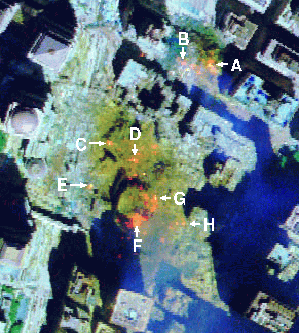
The first hyperspectral image scene used for experiments in this work was collected by the AVIRIS instrument, which was flown by NASA’s Jet Propulsion Laboratory over the World Trade Center area in New York City on 16 September 2001, just 5 days after the terrorist attacks that collapsed the two main towers and other buildings in the WTC complex.Footnote 1 The full data set selected for experiments consists of \(614 \times 512\) pixels, 224 spectral bands, and a total size of (approximately) 140 Mbytes. The spatial resolution is 1.7 m/pixel. The leftmost part of Fig. 9 shows a false color composite of the data set selected for experiments using the 1,682, 1,107 and 655 nm channels, displayed as red, green and blue, respectively. Vegetated areas appear green in the leftmost part of Fig. 9, while burned areas appear dark gray. Smoke coming from the WTC area (in the red rectangle) and going down to south Manhattan appears bright blue due to high spectral reflectance in the 655 nm channel. Extensive reference information, collected by U.S. Geological Survey (USGS), is available for the WTC scene. In this work, we use a USGS thermal mapFootnote 2 which shows the target locations of the thermal hot spots at the WTC area, displayed as bright red, orange, and yellow spots at the rightmost part of Fig. 9. The map is centered at the region where the towers collapsed, and the temperatures of the targets range from 700 to 1,020 K. Further information available from USGS about the targets (including location and estimated size) is reported on Table 1. As shown by Table 1, all the targets are sub-pixel in size since the spatial resolution of a single pixel is 1.7 m2. The information in Table 1 will be used as ground-truth to validate the accuracy of the proposed parallel hyperspectral unmixing algorithms.

False color composition of an AVIRIS hyperspectral image collected by NASA’s Jet Propulsion Laboratory over lower Manhattan on 16 September 2001 (left). Location of thermal hot spot fires in World Trade Center area (right)
A second hyperspectral image scene has been considered for experiments. It is the well-known AVIRIS Cuprite scene (see Fig. 10a), collected in the summer of 1997 and available online in reflectance units after atmospheric correction.Footnote 3 The portion used in experiments corresponds to a \(350 \times 350\)-pixel subset of the sector labeled as f970619t01p02_r02_sc03.a.rfl in the online data, which comprises 188 spectral bands in the range from 400 to 2,500 nm, and a total size of around 50 Mbytes. Water absorption and low SNR bands were removed prior to the analysis. The site is well understood mineralogically, and has several exposed minerals of interest including alunite, buddingtonite, calcite, kaolinite and muscovite. Reference ground signatures of the above minerals (see Fig. 10b), available in the form of a U.S. Geological Survey library (USGS)Footnote 4 will be used to assess endmember signature purity in this work.

a False color composition of the AVIRIS hyperspectral over the Cuprite mining district in Nevada. b U.S. Geological Survey mineral spectral signatures used for validation purposes
4.2 Analysis of algorithm precision
The full hyperspectral unmixing chain was first tested with the AVIRIS scene over the World Trade Center. The number of endmembers to be detected by GPU-FINDR was set to \(p=30\) after calculating the virtual dimensionality (VD) of the hyperspectral data [29]. This value was also used to decide the number of principal components to be retained by GPU-PCA (as the number of endmembers estimated was \(p=30,\) we retained \(d=29\) principal components). An evaluation of the precision of the GPU-LSU in estimating the abundance of the extracted endmembers is contained in Table 1, in which the accuracy of the estimation of the sub-pixel abundance of fires in Fig. 9 can be assessed by taking advantage of the information about the area covered by each thermal hot spot available from U.S. Geological Survey (USGS). Since each pixel in the AVIRIS scene has a size of 1.7 m2, it is inferred that the thermal hot spots are sub-pixel in nature and thus require spectral unmixing in order to be fully characterized. In this regard, the area estimations reported on the last column of Table 1 demonstrate that the considered hyperspectral unmixing chain (implemented using unconstrained abundance estimation) can provide accurate estimations of the area covered by thermal hot spots. In particular, the estimations for the thermal hot spots with higher temperature (labeled as ‘A’, ‘C’ and ‘G’ in the table) are almost perfect.
For illustrative purposes, Fig. 11 shows some of the abundance maps for the most relevant endmembers extracted from the AVIRIS hyperspectral scene after applying the proposed GPU implementation of the full hyperspectral unmixing chain. We recall that endmember abundance maps are the outcome of the unmixing process, where each map reflects the sub-pixel composition (between 0.0 and 1.0) of a certain endmember in each pixel of the scene. Specifically, the maps displayed in Fig. 11 correspond to vegetation (see Fig. 11a), smoke (see Fig. 11b), and fire (see Fig. 11c). Finally, Fig. 12 shows the corresponding spectral endmembers extracted by the proposed method. If we relate the endmember plots with the three channels visible by the human eye (red, green and blue), we can see from Fig. 12 that the smoke endmember exhibits high spectral reflectance in the blue (470 nm) channel, while vegetation exhibits a peak of reflectance in the green (530 nm) channel, hence motivating that the human eye associates green color to vegetation, although the spectral signature of vegetation exhibits many other peaks and valleys. Finally, the fire endmember has high reflectance in the red (700 nm) channel, but it also shows even higher reflectance values in the short-wave infra-red (SWIR) region, located between 2,000 and 2,500 nm. This indicates the much higher temperature of the fires when compared with other representative endmembers in the scene.

Abundance maps extracted by the GPU implementation of the considered unmixing chain for the vegetation (a), smoke (b) and fire (c) endmembers in the AVIRIS World Trade Center scene

Spectral endmembers of vegetation, smoke, and fire extracted from the AVIRIS World Trade Center scene
To conclude this section, we provide an experimental assessment of endmember extraction accuracy with the AVIRIS Cuprite scene. Table 2 shows the spectral angles [7] (in degrees) between the most similar endmember pixels detected by GPU-FINDR and the USGS library signatures in Fig. 10b. The lower the spectral angle, the more similar the spectral signatures are. The range of values for the spectral angle is [0°, 90°]. In this experiment, the number of endmembers to be detected was set to \(p=19\) after calculating the VD of the AVIRIS Cuprite data (hence, the number of retained dimensions was \(d=18\)). As shown by Table 2, the GPU-FINDR extracted endmembers are spectrally very similar to the USGS library signatures, despite the potential variations (due to possible interferers still remaining after the atmospheric correction process) between the ground signatures and the airborne data. Since no reference information is available regarding the true abundance fractions of minerals in the AVIRIS Cuprite data, no quantitative experiments were conducted although the obtained mineral maps exhibit similar correlation with regards to previously published maps.Footnote 5 Since these results have been discussed in previous work (see for instance [27]), we do not display them here.
4.3 Analysis of parallel performance
The proposed GPU implementation of the full hyperspectral unmixing chain has been tested on a NVidia™ GTX 580 GPU, which features 512 processor cores operating at 1.54 GHz, with single precision floating point performance of 1581.1 Gflops, total dedicated memory of 1,536 MB, 2,004 MHz memory (with 384-bit GDDR5 interface) and memory bandwidth of 192.4 GB/s.Footnote 6 The GPU is connected to an Intel core i7 920 CPU at 2.67 GHz with eight cores, which uses a motherboard Asus P6T7 WS SuperComputer. It is important to emphasize that our GPU versions of PCA, N-FINDR and LSU provide exactly the same results as the serial versions of the same algorithms. Hence, the only difference between the serial and parallel algorithms is the time they need to complete their calculations. On the other hand the adopted linear spectral unmixing chain is competitive with regard to other chains. Our main reason for selecting this unmixing chain for implementation is its competitiveness in hyperspectral image unmixing.
The serial algorithms were executed in one of the available cores, and the parallel times were measured in the considered GPU platform. For each experiment, 50 runs were performed and the mean values are reported (these times were always very similar, with differences on the order of a few milliseconds only). Table 3 summarizes the obtained results by the C implementation and by the GPU implementation. An optimization has been considered for the CPU implementation, namely the inclusion of the –O3 optimization flag in the compiler. This optimization could not reach real-time performance in our experiments. As shown by Table 3, the execution time measured after processing the AVIRIS World Trade Center scene on the GPU was only 1.366 s. This result is strictly in real-time, since the cross-track line scan time in AVIRIS, a push-broom instrument [2], is quite fast (8.3 ms to collect 512 full pixel vectors). This introduces the need to process the considered scene (\(614 \times 512\) pixels and 224 spectral bands) in <5.09 s to fully achieve real-time performance.
In the case of the AVIRIS Cuprite scene, the execution time measured on the GPU was only 387 ms. This result is also in real-time since the AVIRIS Cuprite scene needs to be processed in <1.98 s (due to its lower size) to fulfill this requirement. In all cases, the C function gettimeofday() was used for timing the CPU implementations, and the CUDA timer was used for the GPU implementations. It should be noted that the GPU implementations have been carefully optimized taking into account the specific parameters of each considered architecture, including the global memory available, the local shared memory in each multiprocessor, and also the local cache memories as extensively described in Sect. 3. This is confirmed by the fact that the speedups reported on Table 3 are quite significant. Even with the most optimized serial version of the algorithm, the speedup varies between 16.76 and 21.96, which is higher than the one that would be achieved with an optimal parallel implementation of the algorithm that exploits the eight cores of the i7 920 CPU. Although the global GPU memory (1.5 GB) is large enough to store the full hyperspectral image in all considered cases, we accommodated blocks of pixels in small local memories in the GPU to guarantee very fast accesses, thus performing block-by-block processing to speed up the computations as much as possible. Also, we emphasize that the times of the data transfers between CPU and GPU are included in the GPU times reported on Table 3. As shown by the table, in the two considered experiments the data transfer times represent approximately 30 % of the total GPU time.
5 Conclusions and future lines
The ever-increasing spatial and spectral resolutions that will be available in the new generation of hyperspectral instruments for remote observation of the Earth anticipate significant improvements in the capacity of these instruments to uncover spectral signals in complex real-world analysis scenarios. Such capacity demands parallel processing techniques which can cope with the requirements of time-critical applications and properly scale with image size, dimensionality, and complexity. In order to address such needs, in this paper we have developed the first real-time implementation of a full hyperspectral unmixing chain using commodity GPUs. The performance of the proposed implementation has been evaluated (in terms of the quality of the solutions provided and its parallel performance) in the context of two real applications, using an NVidia™ GTX 580 GPU. The experimental results reported in this paper indicate that remotely sensed hyperspectral imaging can greatly benefit from the development of efficient implementations of unmixing algorithms in specialized hardware devices for better exploitation of high-dimensional data sets. In this case, the main contribution of this work is the development of the first real-time implementation of a fully consolidated spectral unmixing chain for hyperspectral image analysis using only one GPU device, with few on-board restrictions in terms of cost and size, which are important when defining mission payload in remote sensing missions (defined as the maximum load allowed in the airborne or satellite platform that carries the imaging instrument). This is a significant contribution to the remote sensing community, as it allows for a more efficient exploitation of hyperspectral data in applications requiring a fast response.
Although in our experiments we observed that the GPU global memory can be considered enough to achieve real-time processing of hyperspectral data given the current data acquisition ratios at modern hyperspectral imaging instruments, the dimensionality of hyperspectral images is ever increasing. This may introduce issues in the future, which could be tackled by resorting to multi-GPU implementations. On the other hand, multi-threaded solutions may also be appealing in this field as they do not require complete porting of the code. As a result, future developments will be also directed towards the development of hyperspectral imaging algorithms on multi-core platforms, as the number of cores in those platforms is ever increasing and there is no need to transfer data to the GPU in this case. We feel that, currently, the compact size, portability, and extremely high number of cores make GPUs an appealing architecture for hyperspectral image processing.
References
Goetz, A.F.H., Vane, G., Solomon, J.E., Rock, B.N.: Imaging spectrometry for Earth remote sensing. Science 228, 1147–1153 (1985)
Green, R.O., Eastwood, M.L., Sarture, C.M., Chrien, T.G., Aronsson, M., Chippendale, B.J., Faust, J.A., Pavri, B.E., Chovit, C.J., Solis, M., Monsch, K.A., Olah, M.R., Williams, O.: Imaging spectroscopy and the Airborne Visible/Infrared Imaging Spectrometer (AVIRIS). Remote Sens. Environ. 65, 227–248 (1998)
Plaza, A., Benediktsson, J.A., Boardman, J., Brazile, J., Bruzzone, L., Camps-Valls, G., Chanussot, J., Fauvel, M., Gamba, P., Gualtieri, J.A., Marconcini, M., Tilton, J.C., Trianni, G.: Recent advances in techniques for hyperspectral image processing. Remote Sens. Environ. 113, 110–122 (2009)
Plaza, A.: Preface to the special issue on architectures and techniques for real-time processing of remotely sensed images. J Real Time Image Process. 4(3), 191–193 (2009)
Plaza, A., Du, Q., Chang, Y.-L., King, R.L.: Foreword to the special issue on high performance computing in Earth observation and remote sensing. IEEE J. Sel. Top. Appl. Earth Obs. Remote Sens. 4(3), 503–507 (2011)
Lee, C.A., Gasster, S.D., Plaza, A., Chang, C.-I., Huang, B.: Recent developments in high performance computing for remote sensing: a review. IEEE J. Sel. Top. Appl. Earth Obs. Remote Sens. 4(3), 508–527 (2011)
Keshava, N.: Spectral unmixing. IEEE Signal Process. Mag. 19(1), 44–57 (2002)
Keshava, N.: A survey of spectral unmixing algorithms. Linc. Lab. J. 14(1), 55–78 (2003)
Plaza, A., Martinez, P., Perez, R., Plaza, J.: A quantitative and comparative analysis of endmember extraction algorithms from hyperspectral data. IEEE Trans. Geosci. Remote Sens. 42, 650–663 (2004)
Bioucas-Dias, J.M., Plaza, A., Dobigeon, N., Parente, M., Du, Q., Gader, P., Chanussot, J.: Hyperspectral unmixing overview: geometrical, statistical and sparse regression-based approaches. IEEE J. Sel. Top. Appl. Earth Obs. Remote Sens. 5, 354–379 (2012)
Plaza, A. Chang, C.-I.: High performance computing in remote sensing. Computer & Information Science Series. Chapman & Hall/CRC Press/Taylor & Francis, Boca Raton (2007)
Plaza, A., Chang, C.-I.: Special issue on high performance computing for hyperspectral imaging. Int. J. High Perform. Comput. Appl. 22, 363–365 (2008)
Paz, A., Plaza, A.: Clusters versus GPUs for parallel automatic target detection in remotely sensed hyperspectral images. EURASIP J. Adv. Signal Process. 2010, 1–18 (2010, Article ID 915639)
Plaza, A., Plaza, J., Vegas, H.: Improving the performance of hyperspectral image and signal processing algorithms using parallel, distributed and specialized hardware-based systems. J. Signal Process. Syst. 50, 293–315 (2010)
Tarabalka, Y., Haavardsholm, T.V., Ksen, I., Skauli, T.: Real-time anomaly detection in hyperspectral images using multivariate normal mixture models and GPU processing. J. Real Time Image Process. 4, 287–300 (2009)
Setoain, J., Prieto, M., Tenllado, C., Tirado, F.: GPU for parallel on-board hyperspectral image processing. Int. J. High Perform. Comput. Appl. 22, 424–437 (2008)
Setoain, J., Prieto, M., Tenllado, C., Plaza, A., Tirado, F.: Parallel morphological endmember extraction using commodity graphics hardware. IEEE Geosci. Remote Sens. Lett. 43, 441–445 (2007)
Sanchez, S., Paz, A., Martin, G., Plaza, A.: Parallel unmixing of remotely sensed hyperspectral images on commodity graphics processing units. Concurr. Comput. Pract. Exp. 23, 1538–1557 (2011)
Plaza, A., Plaza, J., Paz, A., Sanchez, S.: Parallel hyperspectral image and signal processing. IEEE Signal Process. Mag. 28, 119126 (2011)
Plaza, A., Du, Q., Chang, Y.-L., King, R.L.: High performance computing for hyperspectral remote sensing. IEEE J. Sel. Top. App. Earth Observ. Remote Sens. 4, 528–544 (2011)
Christophe, E., Michel, J., Inglada, J.: Remote sensing processing: From multicore to GPU. IEEE J. Sel. Top. Appl. Earth Observ. Remote Sens. 4, 643–652 (2011)
Yang, H., Du, Q., Chen, G.: Unsupervised hyperspectral band selection using graphics processing units. IEEE J. Sel. Top. Appl. Earth Observ. Remote Sens. 4, 660–668 (2011)
Goodman, J.A., Kaeli, D., Schaa, D.: Accelerating an imaging spectroscopy algorithm for submerged marine environments using graphics processing units. IEEE J. Sel. Top. Appl. Earth Observ. Remote Sens. 4, 669–676 (2011)
Wei, S.-C., Huang, B.: GPU acceleration of predictive partitioned vector quantization for ultraspectral sounder data compression. IEEE J. Sel. Top. Appl. Earth Observ. Remote Sens. 4, 677682 (2011)
Schowengerdt, R.A.: Remote Sensing: Models and Methods for Image Processing, 2nd edn. Academic Press, New York (1997)
Richards, J.A., Jia, X.: Remote Sensing Digital Image Analysis: An Introduction. Springer, Berlin (2006)
Winter, M.E.: N-FINDR: an algorithm for fast autonomous spectral end-member determination in hyperspectral data. In: Proceedings of SPIE, vol. 3753, 266–270 (1999)
Plaza, A., Valencia, D., Plaza, J., Martinez, P.: Commodity cluster-based parallel processing of hyperspectral imagery. J. Parallel Distrib. Comput. 66, 345–358 (2006)
Chang, C.-I.: Hyperspectral Imaging: Techniques for Spectral Detection and Classification. Kluwer/Plenum Publishers, New York (2003)
Clint, M., Jenning, A.: The evaluation of eigenvalues and eigenvectors of real symmetric matrices by simultaneous iteration, Comput. J. 13, 76–80 (1970)
Golub, G.H., Van Loan, C.F.: Matrix Computations, 3rd edn, pp. 406–408. Johns Hopkins University Press, Baltimore (1996)
Parlett, B.N.: The Symmetric Eigenvalue Problem. Society for Industrial and Applied Mathematics (1998)
Parlett, B.N., Dhillon, I.S.: Relatively robust representations of symmetric tridiagonals. Linear Algebra Appl. 309(1–3), 121–151 (2000)
Sleijpen, G.L., Van der Vorst, H.A.: A Jacobi–Davidson iteration method for linear eigenvalue problems. SIAM Rev. 42(2), 267–293 (2000)
Saad, Y.: Numerical Methods for Large Eigenvalue Problems, revised edition. Society for Industrial and Applied Mathematics (2011)
Craig, M.D.: Minimum-volume transforms for remotely sensed data. IEEE Trans. Geosci. Remote Sens. 32, 542552 (1994)
Miao, L., Qi, H.: Endmember extraction from highly mixed data using minimum volume constrained nonnegative matrix factorization. IEEE Trans. Geosci. Remote Sens. 45(3), 765777 (2007)
Li, J., Bioucas-Dias, J.: Minimum volume simplex analysis: a fast algorithm to unmix hyperspectral data, In: Proceedings of the IEEE International Geoscience and Remote Sensing Symposium, vol. 3, pp. 250–253 (2008)
Chan, T.-H., Chi, C.-Y., Huang, Y.-M., Ma, W.-K.: A convex analysis-based minimum-volume enclosing simplex algorithm for hyperspectral unmixing. IEEE Trans. Signal Process. 57, 44184432 (2009)
Acknowledgments
This work was supported by national funds through FCT – Fundação para a Ciência e a Tecnologia, under project PEst-OE/EEI/LA0021/2011. This work has also been supported by the European Community’s Marie Curie Research Training Networks Programme under reference MRTN-CT-2006-035927, Hyperspectral Imaging Network (HYPER-I-NET), and by the Spanish Ministry of Science and Innovation (HYPERCOMP/EODIX project, reference AYA2008-05965-C04-02). Sergio Sánchez is sponsored by a research fellowship with reference PTA2009-2611-P, associated with the aforementioned project. Funding from Junta de Extremadura (local government) under project PRI09A110 is also gratefully acknowledged. Last but not least, we gratefully thank the Editor and the three anonymous reviewers for their outstanding comments and suggestions, which greatly helped us to improve the quality and presentation of this manuscript.
Author information
Authors and Affiliations
Corresponding author
Rights and permissions
About this article
Cite this article
Sánchez, S., Ramalho, R., Sousa, L. et al. Real-time implementation of remotely sensed hyperspectral image unmixing on GPUs. J Real-Time Image Proc 10, 469–483 (2015). https://doi.org/10.1007/s11554-012-0269-2
Received:
Accepted:
Published:
Issue Date:
DOI: https://doi.org/10.1007/s11554-012-0269-2