
Abstract
Digital beamforming (DBF) has been studied to obtain automatic beam steering towards desired signals and simultaneous elimination of multipath and jamming signals at GNSS receivers, which is made possible by spatial and temporal digital signal processing. In this paper, the limitations of conventional multipath and jamming suppression techniques, which have been proven and widely used in GPS, are investigated. Different DBF algorithms suitable for GNSS applications are investigated theoretically. New ideas for future development of DBF are presented. The implementation of digital beamforming in FPGA/DSP for practical application environments is also discussed.
Introduction
The performance of Global Navigation Satellite Systems (GNSS/Galileo) depends strongly on the signal reception quality. Antenna arrays with beamforming, particularly digital beamforming (DBF) antennas, are one technique that can be used to simultaneously receive an SOI (signal-of-interest) transmitted by a satellite and attenuate interference, e.g. multipath and jamming signals from other locations/directions. GNSS receivers designed to receive navigation signals from different satellites often encounter the presence of unwanted interference signals. If the navigation signals and the interference occupy the same frequency band—unless the signals are uncorrelated, e.g. CDMA signals from different satellites—then temporal filtering often cannot be used to separate SOIs from interference. However, SOIs and interfering signals usually originate from different spatial locations. This spatial separation can be exploited to separate SOIs from interference using beamforming/spatial filtering at the GNSS receivers and offer the ability to improve signal reception, e.g. to increase the SNIR (signal to noise-plus-interference ratio). This fundamental capability of antenna arrays leads to increased accuracy of the pseudorange measurements, shorter TTFF (time-to-first fix), and improved RAIM (receiver autonomous integrity monitoring) performance of a GNSS receiver, making the use of DBF antennas highly attractive to the GNSS receiver designers, particularly for safety-critical applications.
However, until now the cost of employing DBF antennas has inhibited their widespread use for GNSS civilian applications. They are only used for military GPS receivers. Owing to the outstanding progress that has been made in digital signal processing device technology— e.g. ADC (analog-to-digital converter) or DAC (digital-to-analog converter), FPGA (field programmable gate array), ASIC (application specific integrated circuit), DSP (digital signal processing), combined with recent improvements in memory and I/O bandwidth—in recent years, the role traditionally carried out by analog components is now being performed by digital signal processing units. Now the combination of digital beamforming antennas with software radio makes the application of DBF antennas possible for civilian GNSS receivers.
A DBF antenna combined with flexible digital signal processing enables a variety of complex functions, e.g. multibeam forming, direction of arrival estimation for the desired signals, and interference cancellation. Furthermore, a DBF antenna can metamorphose its configuration by adapting itself to the changing navigation application environment, e.g. urban canyon or suburban areas and airspace; this is achieved through automatic and dynamic changes in both the software (algorithms) and hardware (logic circuitry). It is based on the advent of run-time reconfigurable FPGAs which have a function of instantaneous rewriting the logic circuits at run-time (Harada et al. 2000). The advantages of a DBF antenna are: (1) DBF antennas can mitigate the multipath and jamming effects both on code and carrier phase measurements, because the DBF antennas can simultaneously reduce the multipath-to-signal ratio (MSR) and jammer-to-signal ratio (JSR); and (2) for future developments, a combination of the DBF antenna plus run-time reconfigurable FPGA can be able to dynamically react to the changing environment at any time in the manner of a chameleon by adapting itself in terms of both software (algorithms) and hardware (logic circuits). A basic concept for such a "chameleon" antenna will be provided at the end of this paper.
However, in some cases it could happen that the multipath and jamming signals come nearly from the same direction as the satellite navigation signal, with high probability particularly when satellites with low elevation angles are used. In this case, a DBF antenna cannot improve the reception of the satellite signals while simultaneously eliminating the multipath and in-band interfering signals. However, the temporal and frequency domain processing can overcome this shortcoming of the DBF antenna. Therefore, DBF antennas combined with conventional temporal processing, e.g. narrow correlator, MEDLL, EP (early, prompt) tracking (Meehan and Young 1992), and frequency domain processing are discussed in this paper. Temporal and frequency domain processing in GPS are proven and widely used techniques of multipath and jamming mitigation. Our investigations therefore concentrate mainly on the DBF algorithms.
Conventional and modern techniques for multipath and jamming elimination in GNSS applications and their limitations
In GPS applications there are three conventional techniques used for mitigating multipath and jamming:
Conventional (single antenna) techniques
-
1.
Use of antennas with good low elevation signal rejection capability, such as a choke ring antenna. However, the use of choke ring antennas for multipath mitigation is in contradiction to the all-in-view requirement of satellite navigation, because the satellite signals coming from low elevation are also rejected together with the multipath signals. On the other hand, multipath signals coming from high elevations cannot be eliminated without elimination of the satellite signals.
-
2.
Temporal processing techniques have been developed for reduction of multipath effects on the tracking loops (both DLL and PLL) in GPS applications. In order to identify multipath and LOS signals, these techniques take advantage of the time delay difference between the signals (multipath signals propagate along a longer way than the LOS signals) and include temporal filtering of multipath errors, ELP (early, late, prompt) and EP tracking (Meehan and Young 1992), multipath reduction or correction by narrow correlators and correlation shape correction by using multiple-correlator techniques—e.g. multipath estimation delay lock loop (MEDLL) and strobe and edge correlator multipath mitigation. These methods have been proved successfully for GPS navigation applications but have the following limitations:
-
Most of the techniques have no effect on the multipath-induced carrier phase errors; the only exception to our knowledge is the technique with the limited carrier phase multipath reduction capability reported in (Meehan and Young 1992).
-
Short detour code- and carrier-multipath cannot be eliminated by use of these techniques.
-
Under low C/N0 conditions the performance of these techniques greatly decreases.
-
Long code, e.g. P-code, multipath mitigation is difficult if not impossible for most of the techniques; the only exception to our knowledge is the EP tracking technique with the limited P-code multipath reduction capability reported in (Meehan and Young 1992).
-
-
3.
Frequency domain signal processing techniques, i.e. the collected data are transformed into frequency domain through FFT. These techniques, which are based on the fact that prior to despreading/correlation, a jamming signal is normally high above the noise floor and a multipath signal is weaker than the LOS signal, include frequency domain adaptive filtering and adaptive null steering algorithms, which are practically used for jamming elimination in GPS. However, for multipath signals which include coherent and non-coherent components, as well as long and short detour multipath signals, the assumption does not always hold that the power spectral density (PSD) of the multipath signal is weaker than that of the desired LOS signal. It is difficult if not impossible to identify the desired LOS and multipath signals by only taking advantage of the PSD difference in frequency domain even after despreading/correlation.
Modern digital beamforming (DBF) antenna techniques
A DBF antenna uses an active array of individual antenna elements. Instead of combining or distributing the received signals from each antenna element in the analog stage, it converts analog data to digital data using an A/D converter for processing in a digital stage. Using flexible digital signal processing enables a variety of complex functions, e.g. multibeam forming, direction of arrival estimation, or interference cancellation. The advantages of a DBF antenna are: DBF antennas can simultaneously reduce the MSR and JSR which the jamming-induced and multipath-induced code and carrier phase measurement errors strongly depend on. Therefore, DBF antennas can reduce the multipath and jamming effects both on code and carrier phase measurements.
As discussed above, every technique for the elimination of multipath and jamming has its own advantages and disadvantages (see Table 1). However, the appropriate combination of the techniques, e.g. DBF + temporal processing, DBF +temporal + frequency processing, etc., can overcome the limitations of each individual technique.
Overview of adaptive digital beamforming algorithms applicable for GNSS
Requirements of adaptive beamforming algorithms for GNSS applications
From a receiver point of view, GNSS/Galileo is a one-way (only signal reception) system. Therefore only beamforming algorithms for reception are discussed.
At the moment, DBF algorithms are widely studied in theory and practice for wireless communication systems, e.g. UMTS/IMT-2000. However, because communication and navigation systems are different, some algorithms that are suitable for communication are not applicable for GNSS applications. Therefore, according to our investigations, the requirements on DBF algorithms for GNSS application are summarized as follows:
-
1.
The first and most important requirement from the authors' point of view is that the DBF algorithm used should not cause any significant distortion of the desired GNSS ranging signals, i.e. PRN code and carrier phase, because the purpose of the use of the DBF algorithm is to "clean" the desired navigation signal in order for the navigation receiver to get more accurate pseudorange measurements by using the "cleaned but not distorted" navigation signals. So some widely used DBF algorithms in communication, for example the 2-D RAKE beamformer (Lee et al. 2000), are not applicable for GNSS.
-
2.
Use of as many as possible antenna elements. The spatial resolution of arriving signals depends on the number of elements of an antenna array (Barry et al. 1988). Therefore, the larger the number of the elements the higher the spatial discrimination/resolution capability of the beamforming algorithm for the SOI and multipath and jamming separation. However, a compromise must be found between antenna size and receiver complexity and discrimination/resolution capability. A practicable solution may be an array of 4×4 or 5×5 elements for L-band.
-
3.
For one DBF antenna, there may exist several adaptive algorithms that could be used to adjust the weight vector. The choice of one algorithm over another is determined by the following requirements:
-
Rate of convergence. This is dependent on the number of iterations required for the algorithm in response to a stationary input to converge to the optimum solution. A fast rate of convergence allows the beamforming algorithm to adapt rapidly to a stationary environment of unknown statistics.
-
Tracking. When a DBF antenna operates in a nonstationary mode, the algorithm is required to track all variations in the environment (channel fading, location and attitude).
-
Robustness. Robustness refers to the stability of the algorithm to operate satisfactorily even with ill-conditioned input data.
-
Multitarget beamforming or multiple-input-multiple-output (MIMO) beamforming. In a CDMA-based GNSS system all satellites in the space segment occupy the same frequency band. The adaptive beamforming algorithm in the GNSS receiver must form a beam to each satellite and reduce the interference from other directions simultaneously. For a GNSS receiver with simultaneous reception of P satellite signals, MP multipath signals, J jamming signals, the DBF algorithms used will generate P sets of complex weights, i.e. P weight vectors. These P weight vectors correspond to P different beam patterns that are used to generate P cleaned outputs for further temporal or frequency domain processing in the navigation receiver. Figure 1 shows the structure of a multitarget adaptive digital beamforming with M antenna elements and P output ports. In Fig. 1, y 1(k), . . . ,y p (k) are the outputs of ports 1,2, . . .P, \(\vec W_1 ,\;.\;.\;.\;\vec W_p \) are the M-elements weight vectors of ports 1,2,...P, and k stands for discrete samples. As discussed later, for the reception of P satellite signals and the elimination of MP multipath and J jamming signals, the number P+MP+J must be less than or equal to the number of antenna elements M for some adaptive beamforming algorithms, e.g. direction finding (DF)-based adaptive beamforming algorithms. However, for other algorithms such as CMA (constant module algorithm) and the direction-constrained algorithm described in this paper, it can be greater than the number of antenna elements. From Fig. 1, we can see that the multitarget beamformer can be seen as an MIMO (multi-input multi-output) beamformer.
Fig. 1. 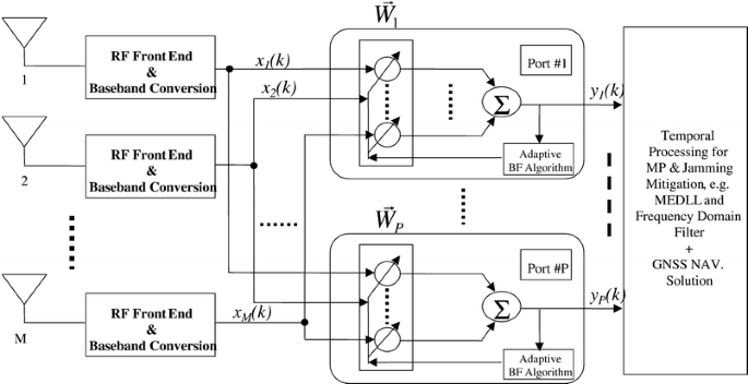
A multitarget DBF antenna with M antenna elements and P output ports
-
Computational requirement. Here the issues of concern include: (1) the number of operations (i.e. multiplications, divisions, and additions/subtractions) required to make one complete iteration of the algorithm; (2) the size of memory locations required to store the data and the program; and (3) the effort required to program the algorithm on a computer or an FPGA/DSP processor.

Digital beamforming algorithms applicable for GNSS
In this section, a survey of adaptive beamforming algorithms is given. Most of these algorithms may be categorized into two classes according to whether a pilot/training signal is used or not. The class of non-blind adaptive algorithms uses a pilot signal to adjust the array weight vector. The other class uses a blind adaptive algorithm which does not require a pilot signal.
Non-blind adaptive beamforming algorithms
In a non-blind adaptive algorithm, a specific pilot signal d(k) with constant data or no data is sent from each satellite to the receivers continuously. The beamformer in the GNSS receiver uses the information of the pilot signal to compute the optimal weight vector \(\vec W\left( k \right)\) as discussed above.
The pilot-signal-based beamforming algorithms offer computationally inexpensive estimates of the signal waveforms, without requiring a preceding DOA (direction of arrival) estimation step. The advantage of this method is that knowledge of the DOA or array manifold is not necessary. Moreover, these beamforming algorithms do not make any assumption about the multipath angle spread and they do not place any structural constraints on the antenna array itself. However, these pilot-signal-based beamforming algorithms can only be used on the condition that the pilot signals are transmitted by the GNSS satellites, which is not the case in the current GPS and GLONASS. However, the new GPS L5 Q-component will contain a pilot signal. For Galileo, currently pilot signals are also planned to be used (Hein et al. 2002).
Blind adaptive algorithms
Blind adaptive algorithms do not require a pilot signal. Instead, they exploit some known properties of the desired received signal. Most of the blind algorithms may be categorized into the following four classes or combinations:
-
1.
Direction finding (DF) algorithms, i.e. adaptive beamforming algorithms based on estimation of the DOAs of the received signals
-
2.
Adaptive beamforming algorithms based on property-restoration techniques
-
3.
Directional constrained adaptive beamforming algorithm
-
4.
Power minimization DBF algorithm.
Adaptive beamforming based on estimation of DOAs of received signals
In the DOA-based or direction finding (DF) adaptive beamforming algorithms, the DOAs of the received signals are first determined by using prior knowledge of the array vector response, i.e. the array geometry. High resolution techniques for DOA estimation include MUSIC (Schmidt 1986) and ESPRIT (Roy and Kailath 1986). After DOAs are estimated, an optimum beamformer is then constructed from the corresponding array response to extract the desired signals from interference and noise (Wang and Cruz 1995).
While DF-based DBF techniques are analytically more tractable, they suffer from several drawbacks that may limit their applicability in GNSS:
-
1.
First, all algorithms start with a DOA estimation step that involves an eigen-decomposition and one or more multidimensional, nonlinear optimizations, which may be a difficult and time-consuming task.
-
2.
The DOA step requires exact knowledge of the array response and is very sensitive to geometric errors.
-
3.
An all-in-view approach is general practice in GNSS applications. If each satellite signal additionally generates two multipath signals, the number of arriving signals can easily exceed the number of antenna elements. However, for common algorithms like MUSIC and ESPRIT, the maximum number of DOAs that can be estimated simultaneously is less than or equal to the number of antenna elements.
-
4.
Moreover, as shown in Fig. 2, due to multipath propagation and the fact that each transmission path may contain direct, reflected and diffracted paths at different time delays, the array response may be poorly defined, and the assumption of a small angle spread, which is also a pre-condition for most DF-algorithms, does not hold. Therefore, DF-based beamforming algorithms are rarely applicable for multipath elimination. However, they could be used for detection and nulling of strong jammers before correlation.
Fig. 2. 
Illustration of the vector channel; parameter φ is the multipath angle-of-spread

Adaptive beamforming based on property-restoration techniques
One of the property-restoration techniques is CMA (constant modulus algorithm). Generally, PSK or BPSK CDMA signals have a constant envelope, if they are not band-limited or they have enough signal bandwidth. This constant envelope may be distorted when the signal is transmitted through the channel. The CMA (Treichler and Larimore 1983, 1985) adjusts the weight vector of the adaptive array to minimize the variation of the envelope at the output of the array. After the algorithm converges, the array can steer a beam in the direction of the signal of interest, and nulls in the directions of interferes.
There is one problem that the CMA-based multitarget blind adaptive beamforming needs to solve. That is how to generate different weight vectors for each output port. For a multitarget non-blind adaptive beamformer, this problem can be solved by using different pilot signals in different ports. For a multitarget blind adaptive beamformer, let us assume that all the signals have the same properties, e.g. the constant modulus property, which is the case in CDMA-based GNSS systems. If additionally there is no other procedure performed during the adaptation of the weight vectors, all these weight vectors in different ports, shown in Fig. 2, can converge to the same vector with the same beam pattern.
To avoid this situation, a Gram-Schmidt orthogonalization (GSO) procedure is used (Agee 1989). However, the GSO is computationally complicated, and some improvements of the GSO should be made in future works.
Directional constrained adaptive beamforming algorithm
This algorithm is based on the principle that if the dynamic of the GNSS receiver is not too high and the beam pattern is not too narrow, e.g. the half power beam width is 10–15°, rough coordinates of the receiver and the coordinates of the satellites in view can be used to calculate the DOAs, i.e. elevation and azimuth, of the SOIs from different satellites. Then the multitarget beamforming weight vectors can be calculated from the directional information in order to steer the beams to the satellites.
This technique is simple to implement in algorithms. However, it is only applicable for applications where the dynamics of the GNSS receiver are not too high. Otherwise, additional sensors for attitude determination are required for mobile receivers.
Space-time power minimization preprocessing
A space-time power minimization preprocessing filter prior to the PRN-code correlators is one of several proposed methods for suppressing jammers. The principle of this algorithm is based on the fact that the GNSS signal prior to despreading/correlation is below the noise floor, e.g. the C/A-code signal from any GPS satellite is in the order of 13 dB below the noise floor. Any signal above the noise floor can be considered as interference. Consequently, the DBF algorithm of the antenna array can be preset to compare any incoming signal with the noise level.
The attractive feature of this space-time power minimization algorithm is the fact that the method can be implemented relatively inexpensively in a separate hardware which can be directly connected to any receiver available on the market without additional modifications. The main disadvantage of the space-time power minimization process is the large dimension of the space-time weight vector. Its computation is complicated. Techniques to reduce the computational complexity need to be developed. Space-time power minimization is attractive for suppression of jammers before correlation/despreading of signals, but is less suitable for MP-mitigation (see the section 'Conventional techniques: single antenna techniques').
Implementation of DBF in GNSS receivers
FPGA implementation of real-time adaptive beamforming algorithms
Three popular methodologies exist for designing computing hardware: application-specific integrated circuits (ASIC), programmable processors such as microprocessors or DSPs, and reconfigurable field programmable gate arrays (FPGAs). A trade-off among them must be made between flexibility and efficiency. Firstly, ASICs are highly specialized for a given application. They can achieve the best possible performance with the lowest silicon cost, but this high efficiency sacrifices flexibility because they are only useful for one task. Secondly, microprocessors and DSPs provide a limited and fixed set of arithmetic and control operations. They are often inefficient when special computation operations are needed or if the computation needs to be executed in parallel. Thirdly, configurable computing machine devices (CCMs) using FPGA have emerged as hybrids between ASICs and programmable processors. They rely on RAM-based field-programmable gate arrays as the mechanism to allow hardware structures to fit the natural organization and data flow of a computation. CCMs allow developers to design their own special function according to their needs and to achieve the concurrency and pipeline advantages needed.
Implementation of DBF after correlation/despreading
The power of GNSS satellite signals and multipath signals is below the noise level when they are arriving at the receiver antenna. The desired signals are recovered again by correlation with the reference PRN-code (despreading). Therefore, DBF before correlation/despreading can eliminate only jammers or strong interferers which are above the noise level, but cannot detect multipath signals and requires a priori information about the satellite positions to steer the beams to the desired signals. In consequence, all adaptive DBF algorithms, which analyze the signals in order to optimize the quality of the SOIs, must be implemented after correlation. The general principle of the DBF implementation after correlation is presented in Fig. 3. Here, the beamforming takes place after PRN code despreading but before the carrier and code tracking loop and discriminators (receiver processing), so that the tracking performance and delay estimation profit from the improved signal quality by the beamforming.

Implementation of DBF after correlation
Ideas for future development
As discussed above, the function of an antenna array combined with DBF is realized by digital signal processing. Although a DBF algorithm implemented in hardware works adaptively to cancel time-varying interferences, its convergence is guaranteed in some environments only. As shown in Fig. 4, as an example of a practical land mobile application, the movement of the GNSS receiver will be accompanied by a variety of propagation environments. According to our investigations, a given algorithm may show excellent suppression under a certain environment and certain dynamics. In rural areas, for example, where normally long detour multipath takes place, multiple antenna diversity (without beamforming) + normal GNSS temporal processing achieves the most satisfactory results for the elimination of multipath. However, for many other environments its ability becomes limited, e.g. in urban and suburban areas, because the multipath signals include short and long detour multipath signals. Here, a pilot-based DBF + normal GNSS temporal processing + frequency multidimensional processing technique is required. Consequently, a single omnipotent DBF algorithm does not exist.

Basic concept of a chameleon antenna implementation
Whether a DBF algorithm can be advantageous or not depends on the application environment. Certainly, a DBF antenna + GNSS receiver can implement different algorithms for different environments in system hardware (e.g. FPGA/DSP or ASIC). However, the hardware load would be too heavy, and this will also cause degradation of the real-time processing capability.
One potential realization of a chameleon-antenna is shown in Fig. 4 (Dick and Harris 1999; Karasawa and Kamiya 2000):
-
1.
Potential application environments are anticipated and the appropriate DBF algorithms are programmed ahead of run time in ROM/EPROM.
-
2.
The environment is automatically sensed and the most suitable DBF algorithm is chosen.
-
3.
The chosen algorithm is implemented instantaneously and put into operation by the run-time reconfigurable FPGA.
Key technologies and further investigations are necessary for the realization of this chameleon-antenna:
-
4.
Real-time sensing and recognition of the mobile environment
-
5.
Achieving optimal navigation quality by means of a smooth transition over different possible adaptive algorithms
-
6.
Configuration and implementation of the selected DBF algorithms during run-time.
For the mapping of different DBF algorithms to different environments, channel measurements and development of the vector multipath channel models (DOA-dependent) are necessary. Such work is currently performed at DLR within different projects.
Conclusions
From the discussions above, we can conclude that a DBF antenna combined with temporal and frequency processing techniques which are proven and widely used in GPS provides a promising way for the "complete" elimination of multipath and jamming interference for the GNSS/Galileo applications. The development of intelligent, computationally efficient DBF algorithms and the outstanding progress of the digital signal processing devices (A/Ds, D/As, I/O, memory, FPGA, ASIC, DSP) are the key for the realization of DBF antennas to be used widely for civilian applications in future GNSS/Galileo systems.
References
Agee BG (1989) Blind separation and capture of communication signals using a multitarget constant modulo beamformer. In: Proc IEEE Military Communication Conf, pp 1921–1927
Barry D, Veen V, Buckley KM (1988) Beamforming: a versatile approach to spatial filtering. IEEE ASSP Mag April
Dick C, Harris FJ (1999) Configurable logic for digital communications. IEEE Commun Mag 37(8):107–111
Harada H, Kamio Y, Fujise M (2000) Multimode software radio system by parameter controlled and telecommunication component block embedded digital signal processing hardware. IEICE Trans Comm E83-B, June, pp 1217–1228
Hein GW, Godet J, Issler J-L, Martin J-C, Erhard P, Lucas-Rodriguez R, Pratt T (2002) Status of Galileo Frequency and Signal Design. In: Proc of ION GPS 2002, Sept. 24–27, Portland, Oregon, pp 266–278
Karasawa Y, Kamiya Y (2000) Algorithm diversity in a software antenna. IEICE Trans Comm E83-B(6):1229–1236
Lee W, Ram J et al. (2000) Joint beamformer RAKE and decorrelating multiuser detector using matrix Levinson polynomials. IEICE Trans Commun E-83-B(8)
Meehan TK, Young LE (1992) On receiver signal processing for GPS multipath reduction. In: Proc 6th Int Geodetic Symp on Satellite Positioning, Columbus, Ohio, 18 March
Roy R, Kailath T (1986) ESPRIT—estimation of signal parameters via rotational invariance techniques. IEEE Trans Acoustics Speech Signal Processing 37:984–995
Schmidt RO (1986) Multiple emitter location and signal parameter estimation. IEEE Trans Ant Prop AP-34(3):276–280
Treichler JR, Larimore MG (1983) A new approach to multipath correction of constant modules signals. IEEE Trans Acoustics Speech Signal Processing ASSP-31(2):459–471
Treichler JR, Larimore MG (1985) New processing techniques based on the constant modules adaptive algorithm. IEEE Trans Acoustics Speech Signal Processing ASSP-33(2):420–431
Wang Y, Cruz JR (1995) Adaptive antenna array for cellular CDMA communication systems. In: Proc IEEE ICASSP, July, pp 1725–1728
Acknowledgements
The authors thank the reviewers of the manuscript for their help and useful comments. This work has been supported by the German Aerospace Center (DLR) (FKZ 50 NA 0104).
Author information
Authors and Affiliations
Corresponding author
Additional information
Based on a paper presented at the GNSS2002 Conference, Copenhagen, 27–30 May 2002
Rights and permissions
About this article
Cite this article
Fu, Z., Hornbostel, A., Hammesfahr, J. et al. Suppression of multipath and jamming signals by digital beamforming for GPS/Galileo applications. GPS Solutions 6, 257–264 (2003). https://doi.org/10.1007/s10291-002-0042-2
Received:
Accepted:
Published:
Issue Date:
DOI: https://doi.org/10.1007/s10291-002-0042-2