
Abstract
In this paper, a closed-chain multibody model of a pantograph/catenary system is developed and used for the optimal design of a nonlinear controller based on an open-loop control architecture. The goal of the nonlinear controller is the reduction of the contact force arising from the pantograph/catenary interaction and, at the same time, the suppression of the mechanical vibrations of the pantograph mechanism. The analytical formulation employed in this paper for describing the nonlinear dynamics of the pantograph/catenary multibody system considers a Lagrangian approach and is based on a redundant set of generalized coordinates. The contact forces generated by the pantograph/catenary interaction are modeled in this work employing an elastic force element collocated between the pantograph pan-head and a moving support. The external support follows a prescribed motion law that simulates the periodic deployment of the catenary system. On the other hand, in this investigation, the algebraic constraints arising from the closed-loop topology of the pantograph multibody system are enforced employing a method based on the Udwadia–Kalaba equations recently developed in the field of analytical dynamics. Furthermore, the problem of the determination of an effective feedforward controller for reducing the pantograph/catenary contact force is formulated in this work as a nonlinear optimal control problem. For this purpose, the solution of the control optimization problem is carried out by using an adjoint-based computational procedure. Numerical simulations demonstrate the effectiveness of the nonlinear controller obtained in this investigation for the pantograph/catenary multibody system.
1 Introduction
The pantograph/catenary system, which represents the object of this investigation, is the prevalent energy collection device for railway trains based on an electric traction [1]. When electrical trains need to operate at a high speed, the stability of the current collection from the railway network becomes a crucial requirement [2]. The proper functioning of the current collection system is determined by the dynamic behavior that results from the pantograph/catenary interaction. Therefore, the pantograph/catenary contact force must be carefully tuned considering the dynamic behavior of the mechanical components of the pantograph mechanisms [3]. To this end, a consistent prediction of the time evolution of the interaction force between the pantograph strips and the catenary wire represents a fundamental aspect in the process of the evaluation of the performance of this form of energy collection system [4]. The dynamic variation of the interaction force between the pantograph and the catenary is due to many different factors such as, for instance, the presence of adverse weather conditions, the nonlinear vibration of the car body, the action of aerodynamic forces, the flexibility of the cables that form the catenary, the induction of nonstationary waves in the catenary wire, and the interaction between multiple energy collectors [5, 6]. In the worst-case scenario, these adverse factors can lead to a complete loss of contact between the pantograph and the catenary or to a damage to the railway infrastructure [7]. Furthermore, several additional parameters influence the wear rates of the mechanical components of the pantograph/catenary system that come in contact. For example, in addition to the magnitude of the contact force, the sliding speed, the materials in contact, and the current intensity are important operational parameters. Therefore, the development of an effective control system for monitoring and influencing the contact force between the catenary wire and the pantograph contact strips can lead to an important improvement in the mechanical performance of the pantograph/catenary system.
This paper is focused on the dynamic analysis of the pantograph/catenary multibody system. The main factors that influence the time evolution of the contact force between the pantograph and the catenary that are of interest for this investigation are the geometric nonlinearity of the closed-loop topology of the pantograph mechanism and the intrinsic nonlinear nature of the pantograph/catenary interaction that generates the contact force. In order to achieve a constant current collection, the contact between the pantograph strips and the catenary wire is imposed by means of the action of an uplift force exerted by a pneumatic actuator operating on the pantograph lower arm [8]. If the uplift force applied is too high, a large contact force between the pantograph strips and the catenary wire is obtained, which, in turn, can lead to an excessive wear of the components in contact due to high friction. On the other hand, if the applied uplift force is too low, a small contact force between the pantograph and catenary system is produced, which can cause a loss of contact leading potentially to electrical arcing. Thus, the design of the uplift force is performed adopting a trade-off strategy between these two contrasting goals [9]. From one side, an important requirement is the achievement of an adequate contact quality resulting from the pantograph/catenary interaction. From the other, the need of a low wear of the components in contact is another necessary requirement. One possible strategy for solving this important problem is represented by the application of an actively controlled pantograph which can improve the contact quality between the pantograph contact strips and the catenary wire [10]. The design of an effective control strategy for an actively controlled pantograph mechanism requires as a preliminary step the development of an accurate multibody model of the pantograph/catenary system in order to correctly capture the geometric nonlinearities of this complex mechanism [11].
In this investigation, the multibody approach to the analysis of constrained mechanical systems is adopted. Multibody systems are mechanical systems composed by collections of rigid bodies, flexible components, kinematic joints, force elements, and control actuators [12,13,14,15]. The complex dynamic behavior of a general multibody system is induced by the presence of high nonlinearities in the equations of motion which are able to capture large reference displacements and large finite rotations [16, 17]. Therefore, general analysis approaches are required in order to describe the dynamic behavior of a general multibody mechanical system [18]. For this purpose, an efficient formulation of the dynamic equations and a consistent derivation of the algebraic equations that define the kinematic joints must be achieved. Considering an analytical approach based on redundant Lagrangian coordinates, the principal methodologies used for the kinematic and dynamic analysis of rigid multibody systems are the reference point coordinate formulation (RPCF) and the natural absolute coordinate formulation (NACF) [19, 20]. In general, all the multibody formulations can be developed for both two-dimensional and three-dimensional systems. For the kinematic description of a rigid body, the RPCF employs a set of orientation coordinates which can be minimal or redundant. In the first case, the minimal set of Euler angles is typically used leading to the RPCF with Euler angles (EA). In the second case, the most common approach is to use the redundant set of Euler parameters leading to the RPCF with Euler parameters (EP) [21]. The NACF, on the other hand, directly employs the set of direction cosines for the definition of the orientation of a rigid body [22]. The main advantage of both the RPCF and the NACF is the fact that the algebraic constraint equations that model the kinematic joints can be modeled in a simple local level even in the case of complex multibody systems [23]. Furthermore, one of the main features of the rigid multibody framework based on redundant coordinates is the possibility of developing efficient and effective computational algorithms for the numerical solution of the dynamic equations of motion grounded on a total Lagrangian approach and characterized by a nonincremental solution procedure [24]. Therefore, the multibody formulation approach discussed in detail in this investigation and used for modeling the pantograph/catenary mechanism is the planar RPCF with EA.
The correct formulation of the dynamic equations that describe the nonlinear behavior of rigid multibody systems is of fundamental importance for solving the optimal control, estimation, and identification problems [25, 26]. In fact, the conventional algorithms based on the linearization of the equations of motion are inappropriate for controlling the nonlinear behavior of multibody systems and more complex design methods, estimation procedures, and control strategies must be employed [27, 28]. One possible approach for addressing these challenging problems relies on the application of advanced nonlinear control and estimation methodologies to the nonlinear dynamics of multibody systems [29,30,31]. For this purpose, the optimal control theory based on the Pontryagin minimum principle can be used leading either to the Hamilton–Jacobi–Bellman partial differential equation or to a set of nonlinear differential-algebraic equations that form a nonlinear two-point boundary-value problem. The Hamilton–Jacobi–Bellman (HJB) equation is the continuous-time analog of the discrete deterministic dynamic programming algorithm [32, 33]. For a given dynamical system with an associated cost functional, the solution of the HJB equation is the function value which corresponds to the minimum cost function and leads to an optimal feedforward (open-loop) controller [34]. However, other computational methods for the design of nonlinear control strategies can also be used for developing a nonlinear control system for a general multibody mechanical system. For example, the feedback linearization method, the sliding mode control, and nonlinear control methods based on the control Lyapunov function can be used for the construction of a nonlinear controller. By means of an appropriate change of variables, the nonlinear control methods based on the feedback linearization approach are able to determine a state feedback control action which transforms the nonlinear system into an equivalent linear system that can be easily controlled. The sliding mode control is a nonlinear control method that alters the dynamics of a mechanical system using a discontinuous control action that forces the dynamical system to evolve toward, or slide along, the boundaries of a multiple dynamic behavior associated with different control structures that are close to a nominal operational point of the state space [35]. The nonlinear control methods based on the on the control Lyapunov function, on the other hand, allows for obtaining a regular stabilizing feedback controller for a nonlinear system from a differentiable control Lyapunov function by using the Artstein theorem [36]. However, as discussed in detail in the paper, the nonlinear control methodology of interest for this study is based on the adjoint equations that form a nonlinear two-point boundary-value problem.
In the literature, several comprehensive studies concerning the recent research challenges pertaining to the mechanical and electrical aspects related to the interaction between the pantograph mechanism and the overhead catenary line can be found, thereby demonstrating the importance of the main problem of interest for this investigation. A detailed overview of the research challenges associated with the interaction between the pantograph system and the overhead equipment connected to the catenary wires can be found in the recent work of Bruni et al. [37]. Chen et al. [38] proposed a new method for describing the contact between pantograph and catenary employing the equation of displacement compatibility. Navik et al. [39, 40] proposed and validated a finite element model for assessing the pantograph/catenary interaction contact forces and developed a numerical procedure for identifying the system damping using field measurements. Song et al. [41] investigated the performance of an active control system by using a multibody model of the pantograph in combination with a nonlinear finite element model of catenary, taking also into account the influence of more realistic conditions, such as the controller time delay and the limitation of controller sensitivity, in order to quantify the influence of such conditions on the performance of the active controller. Lu et al. [42] studied the effects of a double pantograph operating simultaneously, with the contact force on trailing pantograph fluctuating violently due to the passage of leading pantograph, and proposed a prior-information-based finite-frequency H-infinity controller incorporating an adaptive estimator for the active control of the double pantographs. Bautista et al. [43] presented an algorithm capable of simulating the interaction between a catenary system, represented as a finite element model, and a pantograph system, modeled as a multibody linkage, in order to optimize the design of the infrastructure as well as the configuration of the pantograph mechanism. Lee et al. [44] focused on studying the dynamic interaction between the catenary and the pantograph of a high-speed train in order to improve the transmission of electric power to the railway vehicle and obtain stable operations. Ambrosio et al. [45] explored the use of cosimulation procedures that enable to model and analyze the subsystems using different methods and computer codes, while maintaining the synchronism of the forward time integration, and included the deformation in the multibody formulation by using the finite element method to discretize the particular components which exhibit deformations that influence the overall system performance. Massat et al. [46] focused on the numerical modeling of pantograph/catenary interaction and proposed an efficient cosimulation process between finite element and multibody modeling methods. Lee et al. [47] investigated the estimation of the lateral and vertical track irregularities from the measurements of the corresponding axle-box accelerometers in order to monitor the track conditions by in-service high-speed trains employing Kalman-based methods, band-pass, and compensation filters. Seo et al. [48] studied the large aerodynamic lifting force generated in high-speed trains by the contact plate and the body of pantograph and how this phenomenon causes the wear of the catenary contact wire. Lee and Park [49] discussed how the dynamic interaction between the catenary and the pantograph of high-speed trains affects the stable electric power supply and proposed a flexible multibody model which represents an efficient tool for the analysis of the dynamic behavior of the catenary and the pantograph which is also useful for the design of reliable current collection systems. Song et al. [50] proposed a nonlinear finite element model for analyzing the wind-induced mechanical vibrations of the railway catenary system considering a spatial stochastic wind field. Song et al. [51] proposed a nonlinear controller based on the sliding mode approach for a high-speed active pantograph for improving the current collection quality under a strong stochastic wind field. Duan et al. [52] analyzed the contact force of pantograph/catenary mechanism and studied the influence of the friction coupling on the current collection system. Schirrer et al. [53] modeled the complex dynamics of the pantograph/catenary interaction by using a real-time-capable distributed-parameter description in moving coordinates and presented a pantograph test rig with accurate emulation of the catenary system in order to allow efficient, realistic, and reproducible testing. Shi et al. [54] developed a backstepping precise control method for the pantograph/catenary contact load based on a fuzzy logic and considered the influence of wind load as well as the parameters uncertainty on the dynamics of the system. Ren et al. [55] proposed a semi-active control strategy for optimizing the pantograph/catenary coupling based on model predictive control techniques. Guo et al. [56] analyzed the statistical characteristics of contact force arising from the pantograph/catenary interaction by using mathematical statistic methods and demonstrated the fact that the dynamic contact force has a periodic fluctuation which is in accordance with the normal distribution. Wang et al. [57] investigated the potential use of pantograph pan-head vertical acceleration instead of the pantograph/catenary contact force for monitoring the configuration of railway catenaries. The significant interest in the topics related to the pantograph/catenary interaction is apparent in the conspicuous recent literature production and demonstrates also the importance of the problem analyzed in this work.
This work deals with the construction of an effective method for solving the hybrid motion/force control problem of the pantograph/catenary system. In order to achieve this goal, a closed-chain multibody model of a high-speed railway pantograph is developed in the paper. For this purpose, a Lagrangian approach based on a redundant set of generalized coordinates is used in this investigation. Furthermore, an optimal control approach based on the adjoint method is employed in this work for calculating an effective open-loop control action. The cost functional for the development of an optimal feedforward controller is designed in order to penalize the deviation of the pantograph/catenary contact force from the desired set point. The goal of the nonlinear feedforward controller is to reduce the wear of the pantograph contact strips and attenuate the mechanical vibrations of the pantograph mechanism. Numerical simulations confirm the effectiveness of the approach developed in the paper.
The remaining part of this paper is based on the following structure. In Sect. 2, the pantograph/catenary system of interest for this investigation is described in detail. In Sect. 3, background material on the kinematic analysis of two-dimensional rigid multibody systems is recalled and it is used for obtaining a kinematic model of the pantograph system. In Sect. 4, background material on the dynamic analysis of two-dimensional rigid multibody systems is provided and it is employed for constructing a dynamic model of the pantograph system. In Sect. 5, an adjoint-based computational methodology for obtaining an optimal feedforward controller for nonlinear dynamical systems is described considering the fundamental equations of constrained motion for multibody mechanical systems introduced by Udwadia and Kalaba. In Sect. 6, several numerical results obtained employing the multibody modeling approach considered in this work, the Udwadia–Kalaba technique for handling the kinematic constraints, and the nonlinear adjoint-based control optimization method are presented. In Sect. 7, the summary of the manuscript, the conclusions obtained in this investigation, and some comments on the future directions of research are reported.
2 Description of the pantograph/catenary multibody system
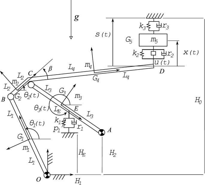
The high-speed railway pantograph system considered in this paper is a Faiveley Transport CX pantograph, and a CAD model of this mechanical system is shown in Fig. 1. On the other hand, a planar rigid multibody model of the pantograph/catenary system developed in this work is shown in Fig. 2. The pantograph/catenary system shown in Fig. 2 is modeled as closed-chain rigid mechanical system. In particular, the high-speed railway pantograph is modeled as a planar mechanism similar to a four-bar linkage. To this end, the thrust rod, the lower arm, and the upper arm of the pantograph are modeled as rigid bodies. However, the effect of the upper link on the pantograph dynamics is neglected. The angle or rotation of the thrust rod is denoted with \({{\theta _1}(t)}\), whereas the angle or rotation of the crank of the upper arm is denoted with \({{\theta _2}(t)}\). The fixed angle or rotation of the upper arm with respect to the crank is denoted with \(\beta \), while the angle or rotation of the lower arm is denoted with \({{\theta _3}(t)}\). The vertical displacement of the pantograph pan-head is denoted with x(t), whereas the vertical displacement of the moving support is denoted with s(t). As shown in Fig. 2, half of the length of the thrust rod is denoted with \({L_1}\), half of the length of the crank of the upper arm is denoted with \({L_2}\), half of the length of the lower arm is denoted with \({L_3}\), and half of the length of the upper arm is denoted with \({L_4}\). The action of the catenary system on the pantograph dynamics is modeled considering an external support having a preassigned motion. The reference height of the moving support is denoted with \({H_0}\). As shown in Fig. 2, the horizontal and vertical coordinates of the revolute joint which connects the lower arm to the ground are, respectively, denoted with \({H_1}\) and \({H_2}\). The mass of the thrust rod is denoted with \({m_1}\), the mass of the crank of the upper arm is denoted with \({m_2}\), the mass of the lower arm is denoted with \({m_3}\), the mass of the upper arm is denoted with \({m_4}\), and the mass of the pan-head is denoted with \({m_5}\). The pantograph/catenary system is subjected to a constant gravitational field having a gravity acceleration denoted with g. A pneumatic actuator provides to the pantograph the lift force necessary for sustaining the contact between the pantograph pan-head and the catenary wire. As shown in Fig. 2, this device is located at an height \({H_E}\) from the ground and it has a distance \({L_E}\) from the center of mass of the lower arm. The pneumatic actuator provides a force field which is modeled considering the combination of a constant lift force \({p_1}\), a linear elastic component with stiffness \({k_1}\), and a linear dissipative component with damping \({r_1}\). A suspension system is collocated between the pantograph pan-head and the tip of the upper arm. This suspension system is modeled with a linear spring having a stiffness \({k_2}\) mounted in parallel with a linear damper having a damping coefficient \({r_2}\). The dynamic behavior of the pantograph/catenary interaction is modeled considering a force field between the moving support that models the catenary and the pantograph pan-head. This force field models the pantograph/catenary interaction considering a linear spring with stiffness coefficient \({k_3}\) and a linear damper with damping coefficient \({r_3}\). The displacement of the moving support is assumed to be a superposition of two sinusoidal functions given by:
where \({S_1}\) and \({S_2}\) are the amplitudes of the two external displacements of the moving support, whereas \({f_1}\) and \({f_2}\) are the frequencies of the two external displacements of the moving support. The periodic movement of the floating support models the interaction between the pantograph and the catenary in a simplified by realistic manner. In particular, the first harmonic function represents the effect of the catenary span on the pantograph dynamics, whereas the second harmonic function represents the effect of the distance between the catenary droppers on the pantograph dynamics. In order to reduce the amplitude of the mechanical vibrations induced by the pantograph/catenary interaction, a control actuator is interposed between the pantograph pan-head and the tip of the upper arm of the pantograph. The external action of the control actuator provided is denoted with u(t). A detailed list of the data used for perming the dynamic simulations of the pantograph/catenary system is reported in Table 1.

CAD model of the high-speed railway CX pantograph
Planar rigid multibody mechanical model of the pantograph/catenary system
3 Pantograph kinematics
3.1 Kinematics of rigid multibody systems
Consider a set of \({n_\mathrm{b}}\) rigid bodies connected by means of a set of \({n_\mathrm{c}}\) mechanical joints. The spatial configuration of this multibody system can be described setting one inertial frame of reference XYZ, which serves as an unique standard for describing the kinematics of the multibody system under examination, and a floating frame of reference \({x_j}{y_j}{z_j}\) for each rigid body j [58]. If \({{\mathbf{r}}_j}({P_j},t)\) is the global position vector of a generic particle \({P_j}\) on the body j, this absolute position vector can be expressed as the sum of global position vector of the origin of the body reference \({{\mathbf{R}}_j}(t)\) and the position vector of the point \({P_j}\) with respect to the origin of the body reference \({{\mathbf{u}}_j}({P_j},t)\) as follows:
where \({{\mathbf{A}}_j}(t)\) denotes the rotation matrix of the body j and \({{{\bar{\mathbf{u}}}}_j}({P_j})\) denotes the position of the point \({P_j}\) with respect to the origin of the body reference expressed using the local coordinates of the material point \({P_j}\). On the other hand, it can be easily proved that the angular velocity \({{\varvec{{\bar{\omega }} }}_j}(t)\) of the body j referred to the local reference system can be computed as:
where \({{\varvec{\tilde{\bar{\omega }} }}_j}(t)\) is a skew symmetric matrix and the angular velocity vector defined with respect to the local frame of reference \({{\varvec{{\bar{\omega }} }}_j}(t)\) is the axial vector associated to this skew symmetric matrix [59]. Let \({\mathbf{q}}(t)\) be the generalized coordinate vector of the multibody system of interest containing the parameters which univocally identify the general configuration of the systems. The time derivative of the position vector \({{\mathbf{r}}_j}({P_j},t)\) of a generic particle \({P_j}\) on the body j can be derived in terms of the time derivative of the generalized coordinate vector \({{ \dot{\mathbf{q}}}}(t)\) as:
where \({{\mathbf{L}}_j}({P_j},t)\) denotes the Jacobian matrix of the position vector relative to the material point \({P_j}\) computed with respect to the system generalized coordinate vector \({\mathbf{q}}(t)\). In particular, the Jacobian matrix of the position vector \({{\mathbf{r}}_j}({G_j},t)\) of the center of mass \({G_j}\) of the rigid body j is of interest for the kinematic analysis and it can be expressed as follows:
where \({{\mathbf{J}}_j}(t)\) denotes the Jacobian matrix of the position vector \({{\mathbf{r}}_j}({G_j},t)\) of the center of mass \({G_j}\) of the rigid body j computed with respect to the system generalized coordinate vector \({\mathbf{q}}(t)\). It is worth to note that the virtual displacement of a material point \({P_j}\) attached to a rigid body j can be found by using the Jacobian matrix \({{\mathbf{L}}_j}({P_j},t)\) as follows:
where \(\delta {\mathbf{q}}(t)\) denotes the virtual change of the system generalized coordinate vector \({\mathbf{q}}(t)\). Furthermore, it can be proved that the angular velocity \({{\varvec{{\bar{\omega }} }}_j}(t)\) of the body j can be expressed as a linear combination of the time derivative of the generalized coordinate vector \({{\dot{\mathbf{q}}}}(t)\) as:
where the matrix \({{{{\bar{\varvec{\Omega }}} }}_j}(t)\) denotes the Jacobian matrix of the angular velocity vector \({{\varvec{{\bar{\omega }} }}_j}(t)\) of the body j computed with respect to the time derivative of the system generalized coordinates \({{\dot{\mathbf{q}}}}(t)\). The kinematic equations discussed before completely describe the configuration of a generic particle \({P_j}\) on the body j in terms of the system generalized coordinate vector \({{\mathbf{q}}(t)}\) and its time derivative \({{\dot{\mathbf{q}}}}(t)\) both referred to an inertial frame of reference XYZ.
3.2 Pantograph kinematic model
The generalized position of a material point on the pantograph can be identified using a set of \({n_2} = 4\) Lagrangian coordinates. The system generalized coordinates can be grouped in a vector \({\mathbf{q}}(t)\) defined as:
where \({{\theta _1}(t)}\), \({{\theta _2}(t)}\), and \({{\theta _3}(t)}\) are the angles of rotation of the thrust rod, crank of the upper arm, and lower arm, respectively, whereas x(t) is the vertical displacement of the pantograph pan-head shown in Fig. 2. Employing this set of \({n_2} = 4\) generalized coordinates, the configuration of the pantograph system can be obtained using the kinematic equations based on a Lagrangian approach that are described in the previous subsection of the paper. In order to achieve this goal, the configuration of all the rigid components that form the pantograph multibody system can be separately analyzed for the geometric description of the motion. The position of a generic point \(P_1\) on the thrust rod referred to a local reference system located at the center of mass of the thrust rod can be identified with a local position vector \({{{\bar{\mathbf{u}}}}_1}(P_1)\) which can be expressed as:
where \({{{{\bar{x}}}_1}(P_1)}\) represents the local abscissa of the point \(P_1\) on the thrust rod. Assuming that the angle of rotation of the thrust rod is denoted with \({{\theta _1}(t)}\) and that the rotation axis of the thrust rod is identified by the fixed unit vector \({{\mathbf{e}}_3} = {\left[ {\begin{array}{*{20}{l}}0&\quad 0&\quad 1\end{array}} \right] ^\mathrm{T}}\), the corresponding rotation matrix \({{\mathbf{A}}_1}(t)\) can be readily calculated as follows:
The position of the thrust rod center of mass \({{\mathbf{R}}_1}(t)\) can be computed exploiting the fixed position of the revolute joint collocated in the point O as follows:
where \({{{\bar{\mathbf{u}}}}_1}(O)\) denotes the position vector of the point O referred to the thrust rod reference system. Therefore, the position of a generic point \(P_1\) on the thrust rod referred to the global reference system can be derived using the fundamental equations of the kinematics of multibody systems as:
The angular velocity vector of the thrust rod referred to the local reference system can be expressed as:
The Jacobian matrix \({{\mathbf{J}}_1}(t)\) of the position vector of the thrust rod center of mass \({{\mathbf{R}}_1}(t)\) can be easily derived as:
The Jacobian matrix \({{\mathbf{L}}_1}(P_1,t)\) of the position vector \({{\mathbf{r}}_1}(P_1,t)\) of a generic point \(P_1\) on the thrust rod can be derived as:
The Jacobian matrix \({{{{\bar{\varvec{\Omega }}} }}_1}(t)\) relative to the thrust rod angular velocity vector \({{\varvec{{\bar{\omega }} }}_1}(t)\) can be computed as follows:
The previous kinematic equations completely describe the thrust rod configuration as functions of the system generalized coordinate vector \({{\mathbf{q}}(t)}\) and its time derivative \({{\dot{\mathbf{q}}}}(t)\). The mathematical descriptions of the geometric configurations of the components that form the pantograph multibody model can be readily obtained following the procedure described in this section as reported in detail in “Appendix A”.
4 Pantograph dynamics
4.1 Dynamics of rigid multibody systems
Once that an adequate kinematic description of the system configuration is obtained in terms of the body generalized positions and orientations, the equations of motion that model the dynamics of the multibody system under study can be derived by using the D’Alembert–Lagrange principle of virtual work. For this purpose, a systematic analytical technique can be employed for effectively computing the mass matrix and the inertia quadratic velocity vector of the bodies which compose the multibody system of interest [60]. Let \({T_j}(t)\) be the kinetic energy of a general rigid body j which belongs to the multibody system of interest. This scalar function can be readily expressed in terms of the system generalized coordinate vector \({{\mathbf{q}}(t)}\) and its time derivative \({{\dot{\mathbf{q}}}}(t)\) [61]. To this end, considering for simplicity a mono-dimensional rigid body j that is of interest for this investigation, the body kinetic energy \({T_j}(t)\) can be explicitly computed as follows:
where \({{\rho _j}}\) is the mass density of the rigid body j, \({{{{\bar{V}}}_j}}\) denotes the volume of the rigid body \({{\varOmega _j}}\), \({{L_j}}\) is half of the length of the mono-dimensional rigid body j, \({{m_j}}\) represents the mass of the body j, and \({{{{{\bar{\mathbf{I}}}}}_{G,j}}}\) denotes the inertia matrix of the body j referred to the body center of mass \({G_j}\). Thus, the rigid body j mass matrix \({{\mathbf{M}}_j}(t)\) can be explicitly written as follows:
On the other hand, consider the virtual work performed by the inertia forces relative to the body j which is denoted as \(\delta {W_{\mathrm{i},j}}(t)\). This scalar quantity can be explicitly written in terms of the system generalized coordinate vector \({{\mathbf{q}}(t)}\) and its time derivative \({{\dot{\mathbf{q}}}}(t)\). In order to do so, consider again for simplicity a general mono-dimensional rigid body j. The virtual work of the inertia forces \(\delta {W_{\mathrm{i},j}}(t)\) can be readily calculated as follows:
where \({{\mathbf{Q}}_{\mathrm{i},j}}(t)\) denotes the Lagrangian component relative to the inertial forces of the rigid body j which can be readily written as follows:
where \({{\mathbf{M}}_j}(t)\) is the body j mass matrix and \({{\mathbf{Q}}_{{\mathrm{v}},j}}(t)\) is the quadratic velocity vector relative to the body j inertial forces that can be explicitly computed as:
where \({{\mathbf{C}}_j}(t)\) is the inertia quadratic velocity matrix of the rigid body j which is defined as:
The generalized inertia forces associated with the rigid body j discussed before completely describe the inertia effects of the rigid body of interest. On the other hand, let \({{\mathbf{F}}_{{\mathrm{e}},j}}(t)\) be an external force acting on the rigid body j and applied to a general point \({{P_j}}\). The virtual work of this external force \(\delta {W_{{\mathrm{e}},j}}(t)\) can be easily calculated as:
where \({{\mathbf{Q}}_{{\mathrm{e}},j}}(t)\) represents the generalized force vector corresponding to the external force \({{\mathbf{F}}_{{\mathrm{e}},j}}(t)\) which can be explicitly derived as follows:
The dynamic equations discussed before completely describe the dynamic behavior of each body j of the rigid multibody system under study in terms of the system generalized coordinate vector \({{\mathbf{q}}(t)}\) and its time derivative \({{\dot{\mathbf{q}}}}(t)\) both referred to an inertial frame of reference XYZ.
4.2 Equations of motion of constrained multibody mechanical systems
The D’Alembert–Lagrange principle of virtual work can be used in conjunction with the Lagrange multiplier technique for the analytical derivation of the differential-algebraic equations of motion of a rigid multibody mechanical systems constrained by kinematic joints [62]. For this purpose, consider a set of \(n_{\mathrm{c}}\) holonomic constraints described by the following set of algebraic equations:
where the vector of holonomic constraints \({\mathbf{f}}(t)\) is a vector function which involves only the generalized coordinate vector \({\mathbf{q}}(t)\) and the time t [63]. A virtual change of the constraint vector yields:
where \({\mathbf{A}}(t)\) is the Jacobian matrix of the constraint function \({\mathbf{f}}(t)\) computed with respect to the generalized coordinate vector \({\mathbf{q}}(t)\). The D’Alembert–Lagrange principle is a direct extension of the principle of virtual work from static analysis to dynamic analysis [64]. Furthermore, the D’Alembert–Lagrange principle combined with the Lagrange multipliers technique can be readily used for obtaining the equations of motion of a multibody system constrained by a set of holonomic algebraic equations. In particular, the basic assumption of classical mechanics is that the constraints perform a zero virtual work. Let \(\delta {W_{\mathrm{c}}}(t)\) be the virtual work of the constraint forces. Considering a set of holonomic constraints described by the vector function \({\mathbf{f}}(t)\), the virtual work of the constraint forces can be computed directly from the virtual change of the constraint equations as follows:
where \({{\varvec{\lambda }}(t)}\) is a vector of Lagrange multipliers corresponding to the holonomic constraint equations and \({{\mathbf{Q}}_\mathrm{c}}(t)\) is the vector of generalized constraint forces associated with the kinematic constraints [65]. On the other hand, consider a set of \(N_\mathrm{b}\) rigid bodies and let \(\delta {W_\mathrm{i}}(t)\) be the virtual work of the inertia forces relative to the entire rigid multibody system under study. This virtual work associated with the system inertia forces can be written as follows:
where \({{\mathbf{M}}(t)}\) denotes the system mass matrix and \({{{\mathbf{Q}}_{\mathrm{v}}}}(t)\) is the system inertia quadratic velocity vector which can be explicitly derived as follows:
where \({\mathbf{C}}(t)\) denotes the system quadratic velocity matrix which is defined as:
On the other hand, let \(\delta {W_{\mathrm{e}}}(t)\) be the virtual work of the system generalized external forces. This virtual work can be calculated as follows:
where \({{\mathbf{Q}}_{\mathrm{e}}}(t)\) denotes the system generalized force vector associated with the external forces which can be obtained as:
The D’Alembert–Lagrange principle of virtual work states that the total virtual work performed by all the forces acting on a mechanical system during a virtual displacement compatible with the kinematic constraints is equal to zero [66]. Since the virtual work of the constraint forces vanishes, the D’Alembert–Lagrange principle can be written as follows:
The substitution of the respective expression for each virtual work in the D’Alembert–Lagrange principle yields:
This vector equation can be reformulated as follows:
where the generalized force vector \({\mathbf{H}}(t)\) is given by:
The vector of generalized coordinates \({\mathbf{q}}(t)\) can be partitioned into a set of independent coordinates \({{\mathbf{q}}_{\mathrm{i}}}(t)\) and a set of dependent coordinates \({{\mathbf{q}}_{\mathrm{d}}}(t)\) as follows:
Similarly, the equations resulting from the D’Alembert–Lagrange principle of virtual work can be partitioned into two sets of dependent and independent equations given by:
The previous equations clearly show that the Lagrange multipliers vector \({{\varvec{\lambda }}(t)}\) couples the two sets of dependent and independent equations of motion by means of the Jacobian matrix of the constraint equations \({\mathbf{A}}(t)\). By performing the vector and matrix multiplications in the preceding equations of virtual work, one obtains:
The vector of Lagrange multipliers \({\varvec{\lambda }}(t)\) represents a vector of additional unknowns of the dynamic problem on hand. Assuming that the Jacobian matrix of the kinematic constraints \({{\mathbf{A}}_\mathrm{d}}(t)\) has a full rank, one can select the vector of Lagrange multipliers \({\varvec{\lambda }}(t)\) to be the solution of the following linear set of algebraic equations associated with the subset of dependent generalized coordinates:
The vector of Lagrange multipliers contains \(n_{\mathrm{c}}\) unknowns which are equal in number to the number of the dependent dynamic equations. On the other hand, since the elements of the vector \({{\mathbf{q}}_{\mathrm{i}}}(t)\) are assumed to be independent because of the initial hypothesis, the D’Alembert–Lagrange principle of virtual work leads to:
Combining the set of dependent equations with the set of independent equations yields:
This set of ordinary differential equations written in matrix form leads to the augmented formulation of the equations of motion of a rigid multibody system [67]. The system dynamic equations must be solved considering at the same time the set of holonomic constraint equations leading to the following system of differential-algebraic equations of motion:
where \({\mathbf{Q}}(t)\) is the total vector of generalized forces that acts on the multibody system which is defined as:
The differential-algebraic equations of motion represent the general form of the equations of motion of a rigid multibody system constrained by kinematic joints and described by holonomic algebraic equations. Furthermore, the differential-algebraic equations of motion define the fundamental problem of constrained motion for a rigid multibody system [68].
4.3 Central equations of constrained dynamics
An effective method can be used to solve the fundamental problem of constrained motion considering the central equations of constrained dynamics. This method is able to derive explicitly the generalized acceleration vector \({{\ddot{\mathbf{q}}}}(t)\) of a multibody system, which can be constrained by a general set of holonomic and nonholonomic algebraic constraints, together with the vector of generalized constraint forces \({{\mathbf{Q}}_{\mathrm{c}}}(t)\) and the vector of Lagrange multipliers \({{\varvec{\lambda }}(t)}\) [69]. In order to apply the resolution method based on the central equations of constrained dynamics to the differential-algebraic equations of motion which characterize the dynamic behavior of a rigid multibody system constrained by kinematic joints, the algebraic equations associated with the kinematic constraints must be represented in a standard form [70]. The standard form of the constraint equations can be readily obtained calculating the second time derivative of the constraint vector \({\mathbf{f}}(t)\) as follows:
where \({\mathbf{A}}(t)\) denotes the Jacobian matrix of the holonomic constraint vector \({\mathbf{f}}(t)\) and \({\mathbf{b}}(t)\) is a quadratic velocity vector relative to the second time derivative of the constraint vector \({\mathbf{f}}(t)\) which can be, respectively, computed as:
On the other hand, considering the virtual work of the constraint forces [71], the vector of generalized forces associated with the kinematic constraints \({{\mathbf{Q}}_{\mathrm{c}}}(t)\) can be explicitly written in terms of the Lagrange multipliers vector \({\varvec{\lambda }}(t)\) as follows:
Employing the standard form of the constraint equations obtained before and adopting the original form of the vector of generalized constraint forces, the equations of motion of a rigid multibody system constrained by kinematic joints can be reformulated in the following matrix form:
It can be proved that the Gauss’s principle of least constraint applied to the previous reformulation of the fundamental problem of constrained motion leads to the central equations of constrained dynamics [72]. These equations are also called Udwadia–Kalaba equations by the name of their discoverers and can be written in a compact matrix form as follows:
where \({\mathbf{a}}(t)\) is the generalized acceleration vector relative to the multibody system released from the kinematic constraints, \({\mathbf{e}}(t)\) is the generalized error vector relative to the acceleration of the multibody system released from the kinematic constraints, \({{\mathbf{F}}(t)}\) is a feedback matrix relative to the generalized acceleration vector of the multibody system constrained by the holonomic constraints, and \({{\mathbf{G}}(t)}\) is a feedback matrix relative to the vector of generalized constraint forces which act on the constrained multibody system [73, 74]. Assuming that the mass matrix \({\mathbf{M}}(t)\) has full rank, the generalized acceleration vector relative to the multibody system released from the kinematic constraints \({\mathbf{a}}(t)\) can be explicitly computed as:
The generalized error vector \({\mathbf{e}}(t)\) analytically quantifies how much the generalized acceleration vector of the rigid multibody system released from the kinematic constraints violates the algebraic constraint equations acting on the system. This vector can be readily computed as follows:
Assuming that the mass matrix \({{\mathbf{M}}(t)}\) has full rank and that the row rank of the Jacobian matrix of the constraint equations \({{\mathbf{A}}(t)}\) is equal to the number of constraint equations \(n_\mathrm{c}\), it can be proved that the feedback matrix of the constrained multibody system \({{\mathbf{F}}(t)}\) can be computed as follows:
where \({{\mathbf{B}}(t)}\) and \({{\mathbf{D}}(t)}\) are two constraint matrices defined as:
On the other hand, the feedback matrix of the generalized forces vector denoted with \({{\mathbf{G}}(t)}\) can be readily computed as:
The central equations of constrained dynamics based on the Udwadia–Kalaba methodology allow for solving the fundamental problem of constrained motion of a rigid multibody system by means of a transformation of the set of index-three differential-algebraic equations into a set of index-one differential-algebraic equations amenable to be treated as ordinary differential equations. However, in general, this analytical process based on the Udwadia–Kalaba equations requires the use of a constraint stabilization technique in order to eliminate the drift phenomenon of the kinematic constraints. The problem of the constraint drift is the violation of the constraint equations at the position and velocity levels due to the alternative differentiation of the constraint equations for lowering the index of the differential-algebraic system of equations of motion and obtaining the standard differential form of the constraint equations. For solving this problem, well-known techniques are available in the multibody literature such as the Baumgarte stabilization method, the penalty approach, and the generalized coordinate partitioning technique. As discussed in detail in the numerical results section (Sect. 6) of the paper, in this investigation a numerical procedure based on the generalized coordinate partitioning technique was used for the stabilization of the algebraic equations that model the kinematic constraint of the pantograph/catenary rigid multibody system.
4.4 Pantograph dynamic model
Denoting with \({m_1}\) the mass of the thrust rod and assuming that the thrust rod has a diagonal inertia matrix \({{\bar{\mathbf{I}}}_1} = \mathrm{diag}\left( {{{{\bar{I}}}_{xx,1}},{{{\bar{I}}}_{yy,1}},{{\bar{I}}_{zz,1}}} \right) \) where \({{\bar{I}}_{zz,1}} = \frac{1}{3}{m_1}L_1^2\), the corresponding mass matrix \({{\mathbf{M}}_1}(t)\) of the thrust rod can be calculated by using the analytical description of its configuration as follows:
The generalized matrix relative to the centrifugal and Coriolis inertia effects of the thrust rod \({{\mathbf{C}}_1}(t)\) can be computed using the analytical description of the thrust rod configuration as follows:
The inertia quadratic velocity vector of the thrust rod \({{\mathbf{Q}}_{{\mathrm{v}},1}}(t)\) can be easily derived as:
The weight force of the thrust rod \({{\mathbf{F}}_{g,1}}(t)\) can be represented in a vector form as:
The generalized force vector relative to the weight of the thrust rod \({{\mathbf{Q}}_{g,1}}(t)\) can be computed as follows:
The previous dynamic equations completely describe the thrust rod inertia and gravitational effects as functions of the system generalized coordinate vector \({{\mathbf{q}}(t)}\) and its time derivative \({{\dot{\mathbf{q}}}}(t)\). The mathematical descriptions of the inertia terms and of the generalized forces of the components that form the pantograph multibody model can be readily obtained following the procedure described in this section as reported in details in “Appendix B”.
4.5 Pantograph constraint equations
Since the topological structure of the pantograph is equivalent to a closed chain, the constraint equations can be readily derived considering simple closed-loop equations. These equations can be easily derived considering the geometry of the OBCA four-bar linkage shown in Fig. 2 as follows:
The loop equations impose a position-level set of constraint equations on the pantograph generalized coordinates which can be expressed as follows:
where the constraint vector function \({\mathbf{f}}(t)\) can be computed in terms of the system generalized coordinates as:
In order to be able to use the Udwadia–Kalaba method, this set of the constraint equations must be recast in the standard form that allows for computing the explicit expression of the constraint generalized forces by means of the fundamental equations of constrained motion. This task can be readily performed computing the second time derivative of the constraint equations as follows:
One can rewrite the previous equations as follows:
where the system constraint matrix \({\mathbf{A}}(t)\) and the system constraint vector \({\mathbf{b}}(t)\) can be obtained as follows:
Employing the analytical expressions of the constraint matrix \({\mathbf{A}}(t)\) and of the constraint vector \({\mathbf{b}}(t)\), the generalized forces vector relative to the closed-loop constraint equations \({{\mathbf{Q}}_{\mathrm{c}}}(t)\) can be explicitly derived using the fundamental equations of constrained motion as:
where the constraint matrix \({\mathbf{G}}(t)\) and the constraint vector \({\mathbf{e}}(t)\) are, respectively, defined as follows:
The explicit expression of the constraint forces corresponding to the closed-loop constraint equations considerably simplifies the mathematical structure of the equations of motion of the pantograph/catenary multibody system. Furthermore, the analytical form of the dynamic equations of the pantograph/catenary multibody system allows for the use of the general methodologies of the optimal control theory for the development of a nonlinear controller based on the adjoint method.
4.6 Equations of motion of the constrained pantograph
Considering the matrix and vector quantities obtained for the dynamic model of the pantograph/catenary system, the equations of motion of this mechanism constrained by kinematic joints can be readily derived using the methods of Lagrangian dynamics leading to the index-one set of differential-algebraic equations given by Eq. (50). In Eq. (50), \({\mathbf{M}}(t)\) denotes the total system mass matrix of the pantograph/catenary multibody system, \({\mathbf{Q}}(t)\) denotes the total system generalized force vector of the pantograph/catenary multibody system, \({{\mathbf{Q}}_{\mathrm{c}}}(t)\) denotes the generalized forces vector relative to the closed-chain constraint equations, \({\mathbf{A}}(t)\) denotes the system closed-chain constraint matrix, and \({\mathbf{b}}(t)\) denotes the system closed-chain constraint vector. Furthermore, employing the fundamental equations of the constrained motion based on the Udwadia–Kalaba method, the equations of motion of the pantograph/catenary multibody system can be rewritten as follows:
where the constraint matrix \({\mathbf{G}}(t)\) and the constraint vector \({\mathbf{e}}(t)\) are defined in terms of the closed-chain constraint equations applied on the pantograph/catenary dynamic model. From the computational point of view, exploiting the explicit expression of the closed-chain constraint forces one can perform the numerical integration of the system equations of motion employing an explicit integration method and, subsequently, the algebraic constraint equations can be enforced at both the position and velocity levels by means of a standard constraint stabilization algorithm. On the other hand, from the control design viewpoint, the compactness of the analytical expression relative to the closed-chain constraint forces considerably facilitates the synthesis of a nonlinear feedforward controller employing the iterative adjoint-based control optimization method discussed in the paper.
5 Pantograph nonlinear control
5.1 Elements of optimal control theory
The objective of optimal control theory is to develop analytical methods capable of constructing optimal control actions. A control law is considered optimal when it is able to satisfy the design constraints imposed on a given dynamical system. The design constrains are mathematically formulated in terms of a performance index. Therefore, an optimal controller is a control law that minimizes the performance index formulated for a nonlinear dynamical system. Consider a dynamical system described by the following set of nonlinear differential equations:
where \({{\mathbf{z}}(t)}\) denotes the system state vector and \({{\mathbf{n}}(t)}\) is the nonlinear system state function. The central idea of the optimal control theory is to find a control action \({{\mathbf{u}}(t)}\) that minimizes a cost functional \(J_\mathrm{c}\) that mathematically describes the goal of the control system [75]. To this end, the mathematical methods of calculus of variations can be effectively used. The cost functional \(J_\mathrm{c}\) is a quantitative expression which can be used to determine the performance of a particular control law \({{\mathbf{u}}(t)}\) in terms of the prescribed design goals [76]. A general cost functional can be defined as:
where h(t) and g(t) are two analytical functions, respectively, referred to as the terminal cost function and the current cost function or the cost-to-go function. In the optimal control theory, system state-space equations (72) are interpreted as a set of dynamic constraints for the minimization problem of the performance index. An effective approach for the solution of this complex problem is based on the principal analytical techniques of the calculus of variation. In particular, the variational techniques for the minimization of a functional can be used employing the Pontryagin minimum principle in order to obtain the necessary conditions which identify the minimum of the performance index [77]. To this end, the first step consists in adjoining system state-space equations (72) to cost functional (73) in order to obtain an augmented cost functional \({\bar{J}_\mathrm{c}}\) as follows:
where \({{\mathbf{v}}(t)}\) is a costate or adjoint state vector which contains the Lagrange multipliers that arise from adjoining the state-space equations of motion (72) to cost functional (73) [78, 79]. In order to simplify the mathematical derivation of the equations for the identification of an optimal control law, the system Hamiltonian function H(t) can be defined as:
According to the Pontryagin minimum principle, an optimal control action \({{\mathbf{u}}^ * }(t)\) is identified by the minimum of the Hamiltonian function \({H^ * }(t)\) [80]. In order to obtain the equations which define the minimum of the Hamiltonian function, the augmented cost functional \({{\bar{J}}_\mathrm{c}}\) can be expressed in terms of the Hamiltonian function H(t) by using the integration by parts rule as follows:
The first variation of the augmented cost functional \({{\bar{J}}_\mathrm{c}}\) can be written as:
where \({{\mathbf{A}}_{\mathrm{c}}}(t)\) and \({{\mathbf{B}}_{\mathrm{c}}}(t)\) are, respectively, the state function sensitivity matrix with respect to the system state and the state function sensitivity matrix with respect to the control action, whereas the vectors \({\varvec{\eta }}(t)\), \({\varvec{\varphi }}(t)\), and \({\varvec{\psi }}(t)\) denote, respectively, the terminal cost function sensitivity vector with respect to the system state, the current cost sensitivity vector with respect to the system state, and the current cost sensitivity vector with respect to the control action. These sensitivity matrices and vectors are explicitly defined as follows:
Assuming that the system initial state \({{{\mathbf{z}}_0}}\) is known and that the final time T is fixed [81], the necessary conditions for the minimization of the cost functional \(J_{\mathrm{c}}\) can be computed employing the fundamental theorem of the calculus of variation by setting the first variation of the augmented cost functional \({{\bar{J}}_\mathrm{c}}\) equal to zero as follows:
It is important to note that the first set of differential equations coincides with the state-space form of system dynamical equations (72), while the second set of differential equations (80) represents the so-called costate equations or adjoint state equations [82]. The third set of algebraic equations (81), on the other hand, is called stationarity conditions. State equations (72) involve a set of initial conditions at the time instant \(t = 0\), whereas adjoint equations (80) involve a set of terminal conditions at the time instant \(t = T\). Stationary conditions (81) are algebraic equations which identify the minimum of the cost functional [84]. The resulting set of differential-algebraic equations represents the necessary conditions for solving the constrained minimization problem of the cost functional \(J_{\mathrm{c}}\). These equations form a two-point boundary-value problem which can be recasted in the following compact form:
The set of the system state-space equations together with the adjoint equations constitutes a coupled nonlinear two-point boundary-value problem which must be solved in conjunction with the set of algebraic equations called stationarity conditions. Finding an analytical solution for this complex mathematical problem is challenging. However, some effective numerical methods are available for obtaining an approximate solution of a certain class of differential-algebraic nonlinear two-point boundary-value problems. Among these numerical methods, the adjoint-based control optimization procedure is of interest for this investigation and is discussed in the next subsection.
5.2 Adjoint method for control optimization
The adjoint method is an iterative method that can be used for numerically solving the nonlinear two-point boundary-value problem (82) resulting from the minimization of the cost functional \(J_{\mathrm{c}}\). This method is based on nonlinear optimization techniques and adopts an iterative adjoint-based control optimization approach [85]. In particular, the adjoint method is suitable for performing an effective and efficient computation of a set of control actions for dynamical systems with a large number of degrees of freedom [86]. The basic idea behind the adjoint method is to exploit the numerical evaluation of the cost functional gradient \({{\mathbf{G}}_{\mathrm{c}}}(t)\) in the minimization process of the cost functional \(J_{\mathrm{c}}\). By doing so, the nonlinear control optimization problem can iteratively solved employing well-known numerical techniques for the minimization of multivariable functions [87]. For this purpose, the adjoint-based optimization procedure starts from a trial time history of the desired control action \({{\mathbf{u}}^0}\). Subsequently, using the current estimation of the time history of the control action \({{\mathbf{u}}^k}\) (or the initial trial guess of the control action \({{\mathbf{u}}^0}\) at the first iteration), the system state equations (72) and the system adjoint equations (80) are solved numerically performing, respectively, a forward and a backward marching on the time grid. The results of this process are a trial time history of the system state \({{\mathbf{z}}^k}\) and a trial time history of the adjoint vector \({{\mathbf{v}}^k}\). In general, the time history of the cost functional gradient \({\mathbf{G}}_{\mathrm{c}}^k\) corresponding to the estimated time histories of the system state \({{\mathbf{z}}^k}\) and to the system costate \({{\mathbf{v}}^k}\) is different from zero. Therefore, since in a general step of this iterative method the numerical solution for the control action does not correspond to the cost functional minimum, the computation of the cost functional gradient \({\mathbf{G}}_{\mathrm{c}}^k\) can be used in the minimization procedure of the cost functional in order to identify the direction of the minimum. In particular, the time history of the cost functional gradient \({\mathbf{G}}_{\mathrm{c}}^k\) can be computed explicitly from stationary equations (81) once that the time history of the system state \({{\mathbf{z}}^k}\) and the time history of the adjoint state \({{\mathbf{v}}^k}\) are known as follows:
where \({{\mathbf{B}}_{\mathrm{c}}^k}\) and \({{\varvec{\psi }}^k}\) denote, respectively, the time history of the state function sensitivity matrix computed with respect to the control action and the time history of the current cost sensitivity vector computed with respect to the control action. The time history of the cost functional gradient \({\mathbf{G}}_{\mathrm{c}}^k\) can be used in an iterative gradient-based optimization algorithm in order to gradually improve the estimation of the optimal time history of the control action \({{\mathbf{u}}^k}\). By doing so, the minimization procedure is automatically directed toward the minimum of the cost functional which corresponds to the solution of the control optimization problem [88]. In particular, the minimization algorithms based on a line search strategy make use of a time history of a prescribed descent direction \({{\mathbf{e}}^k}\). The descent direction \({{\mathbf{e}}^k}\) is used for the computation of the minimum of the cost functional by means of a line search algorithm. The research of the minimum along this direction allows for improving the estimation of the numerical solution of the optimization problem from the current time history of the control action \({{\mathbf{u}}^k}\) to the next time history of the control action \({{\mathbf{u}}^{k + 1}}\) which corresponds to a lower value of the cost functional. Therefore, the time history of the control action can be iteratively updated using a line search method as follows:
where \({\alpha ^k}\) is a line parameter which represents the length of the step corresponding to the current iteration. Several minimization methods based on a line search strategy are available in the literature. In general, the minimization algorithms based on a line search strategy differ from each other on the method used for the computation of the time history of the descent direction \({{\mathbf{e}}^k}\). However, all the methods for computing the vector of descent direction \({{\mathbf{e}}^k}\) are based on the use of the time history of the cost functional gradient. The solution for the length of the step \({\alpha ^k}\) of the line search can be readily found employing a minimum search algorithm for functions of one variable as follows:
The complete numerical procedure for the computer implementation of the iterative adjoint-based control optimization method can be summarized as follows:
-
Step 1—Direct problem solution: Use the current time history of the optimal controller \({{\mathbf{u}}^k}\) (or a trial time history \({{\mathbf{u}}^0}\) for the control action at the first iteration) for numerically solving forward in time system state-space equations (72) using as boundary conditions the assigned set of initial conditions \({\left. {\mathbf{z}} \right| _0} = {{\mathbf{z}}_0}\). This computational step leads to the determination of the current state trajectory \({{\mathbf{z}}^k}\). To this end, explicit or implicit Runge–Kutta methods can be used.
-
Step 2—Adjoint problem solution: Use the current state trajectory \({{\mathbf{z}}^k}\) for numerically solving backward in time the system adjoint state equations (80) using as boundary conditions the set of terminal conditions \({{{\left. {{\mathbf{v}}(t)} \right| }_T} = {{\left. {{\varvec{\eta }}(t)} \right| }_T}}\). This computational step leads to the determination of the current adjoint state trajectory \({{\mathbf{v}}^k}\). To this end, explicit or implicit Runge–Kutta methods can be used.
-
Step 3—Gradient computation: Employing the explicit expression (83) originating from the stationary equations (81), use the current state trajectory \({{\mathbf{z}}^k}\) and the current adjoint state trajectory \({{\mathbf{v}}^k}\) to compute the current time history of the cost functional gradient \({\mathbf{G}}_{\mathrm{c}}^k\).
-
Step 4—Search direction computation: use the current time history of the cost functional gradient \({\mathbf{G}}_{\mathrm{c}}^k\) for the computation of the current time history of the search direction \({{\mathbf{e}}^k}\). To this end, the steepest descent method, conjugate gradient methods, or quasi-Newton methods can be used.
-
Step 5—Initial guess computation: Compute an initial guess of the step length \(\alpha ^0\) for the initialization of the minimum search algorithm based on a line search. To this end, the Taylor series method can be used.
-
Step 6—Bracketing: Use the initial guess for the length of the minimization step \({\alpha ^0}\) for performing the bracketing of the minimum of the cost functional \(J_{\mathrm{c}}\) in an interval \({a^0}\), \({b^0}\), and \({c^0}\) along the time history of the search direction \({{\mathbf{e}}^k}\). To this end, the Fibonacci method or the golden section method can be used.
-
Step 7—Minimization: Use the bracketed interval identified by the triplet \({a^0}\), \({b^0}\), and \({c^0}\) for the minimization of the cost functional \(J_{\mathrm{c}}\) along the time history of the search direction \({{\mathbf{e}}^k}\). This computational step leads to the determination of the step length \({\alpha ^k}\) corresponding to the local minimum of the cost functional. In this computational step, the time history of the control action \({{\mathbf{u}}^{k + 1}}\) is updated using a line search strategy (84). To this end, the Fibonacci search method, the golden section search method, or the Brent search method can be used. If the convergence criterion of the iterative procedure is not satisfied, restart from step 1.
The numerical solution of the nonlinear two-point boundary-value problem given by Eq. (82) provides the optimal time history of the control action \({{\mathbf{u}}^ * }\), the optimal time history of the system state trajectory \({{\mathbf{z}}^ * }\), and the optimal time history of the adjoint state trajectory \({{\mathbf{v}}^ * }\) corresponding to the minimum value of the cost functional \(J_{\mathrm{c}}^ * \). As shown in the numerical results section (Sect. 6), the adjoint method for optimal control is used in this paper for the determination of an optimal feedforward controller for the reduction in the contact force between the pantograph pan-head and the catenary wire.
5.3 Pantograph state-space model
The dynamic model of the pantograph multibody mechanical system can be readily converted from the second-order configuration-space representation given by Eq. (71) to the first-order state-space representation given by Eq. (72) by using the analytical approach developed in the paper. To this end, one can define the following state vector:
By doing so, one obtains the following explicit definition of the nonlinear state function for the pantograph/catenary system:
Since by using the proposed analytical approach the state function \({\mathbf{n}}(t)\) of the pantograph mechanism is written in a closed form, one can readily apply the adjoint method for the numerical calculation of an optimal open-loop control action for regulating the pantograph/catenary interaction.
6 Numerical results and discussion
6.1 Numerical integration of the multibody equations of motion
The mechanical model of the pantograph/catenary multibody system discussed in the paper was implemented in a general-purpose multibody code developed by the authors in the MATLAB simulation environment. By doing so, several numerical simulations were performed to validate the proposed model in different dynamic scenarios that reproduce the pantograph/catenary interaction. In particular, the computational procedure utilized for performing the numerical simulations presented in this section belongs to the broad class of the numerical methods for the dynamic simulations of multibody mechanical systems. This class of computational methodologies exploits both the differential index reduction strategy and the constraint stabilization technique based on the projection algorithm for the orthogonalization of the algebraic equations associated with the kinematic joints. To this end, the computational procedure adopted in the paper considers an effective combination of the classical fourth-order explicit Runge–Kutta method, which is used for the time marching of the numerical solution, with the generalized coordinate partitioning technique, which is employed for eliminating the violations of the constraint equations. An effective and efficient combination of this two important computational methods can be performed with use of the Udwadia–Kalaba method for deriving the generalized constraint forces in an explicit form [89]. In particular, the procedure employed in this paper for the numerical integration of the system equations of motion consists of two stages that are repeated at each time step of the numerical simulation. In the first step of the computational algorithm employed in this work, a fourth-order explicit Runge–Kutta method with fixed time step is implemented in order to march forward in time the numerical solution of the equations of motion. In the second step of the computational procedure used in this paper, the system state resulting from the time marching of the equations of motion is partitioned in dependent and independent coordinates and, subsequently, the constraint equations are enforced numerically at both the position and velocity levels. The enforcement of the kinematic constraints is achieved first by projecting the dependent generalized coordinates onto the manifold of the numerical solution for the constraint equations at the position level and, subsequently, by solving a system of linear algebraic equations associated with the dependent generalized velocities for the constraint equations at the velocity level [90]. To this end, a customized Newton–Raphson iterative procedure is used for imposing the constraint equations at the position level and the standard LU factorization with the Gaussian elimination and backward substitution is employed for imposing the constraint equations at the velocity level. Therefore, the computational method used in this paper leads to an approximate solution of the nonlinear set of the pantograph/catenary equations of motion that is physically correct and numerically stable.
6.2 Numerical simulations of the pantograph dynamics
The numerical results reported in this subsection show a set of numerical simulations performed using the computational procedure for the numerical solution of the differential-algebraic multibody equations of motion described previously. All the numerical simulations discussed in this subsection are performed without considering the control input, and therefore, they correspond to the regular operating conditions of the pantograph/catenary multibody system. The time step used for the numerical simulations is equal to \(\Delta t =\) 0.020 (s), whereas the time span considered for the dynamic analysis is \(T = 10.000\) (s). In this scenario, the time evolution of the angle of rotation and of the angular velocity of the thrust rod is represented, respectively, in Figs. 3a and 4a; the time evolution of the angle of rotation and of the angular velocity of the crank is represented, respectively, in Figs. 5a and 6a; the time evolution of the angle of rotation and of the angular velocity of the lower arm is represented, respectively, in Figs. 7a and 8a; the time evolution of the displacement and of the velocity of the pan-head is represented, respectively, in Figs. 9a and 10a; and the time evolution of the contact force between the pantograph system and the catenary wire is represented in Fig. 11a. Since in this scenario the magnitude of the contact force is considered too large, thereby leading to an excessive wear of the contact components that form the pantograph pan-head, a control action needs to be designed in order to decrease the amplitude of the contact force which arises from the pantograph/catenary interaction.

Thrust rod angular displacement

Thrust rod angular velocity

Crank angular displacement

Crank angular velocity

Lower arm angular displacement

Lower arm angular velocity

Pan-head displacement

Pan-head velocity

Pantograph/catenary contact force
6.3 Optimal control design
The computational procedure used for the optimal synthesis of the control action makes use of the adjoint-based numerical procedure developed in this work. In particular, a feedforward controller is designed by using the iterative adjoint-based control optimization method. The purpose of the feedforward controller designed in this paper is twofold. First, the control strategy must reduce the mechanical vibrations of the pantograph multibody system induced by the moving support that simulates the external action of the catenary wire. At the same time, the function of the control action is to attenuate the contact force arising from the interaction of the pantograph pan-head and the catenary wire which is modeled by using the moving support. The reduction in the contact force must be such that the mean value of the contact force is not affected because it must guarantee the correct functioning conditions of the multibody system, which are based on the contact between the pantograph pan-head and the catenary wire. For the problem at hand, the contact force between the pantograph and the catenary F(t) can be modeled as follows:
In this investigation, the terminal cost function h(t) is designed as follows:
where \({{\mathbf{Q}}_T}(t) = \mathrm{diag}({Q_{T,1}}(t),{Q_{T,2}}(t),{Q_{T,3}}(t),{Q_{T,4}}(t),{Q_{T,5}}(t),{Q_{T,6}}(t),{Q_{T,7}}(t),{Q_{T,8}}(t))\) is a diagonal weight matrix which characterizes the structure of the terminal cost function h(t). On the other hand, the cost-to-go function g(t) is designed as:
where \({{\mathbf{Q}}_z}(t) = \mathrm{diag}({Q_{z,1}}(t),{Q_{z,2}}(t),{Q_{z,3}}(t),{Q_{z,4}}(t),{Q_{z,5}}(t),{Q_{z,6}}(t),{Q_{z,7}}(t),{Q_{z,8}}(t))\), \({{\mathbf{Q}}_u}(t) = {Q_u}(t)\), and \({{\mathbf{Q}}_{\mathrm{F}}}(t) = {Q_{\mathrm{F}}}(t)\) are diagonal weight matrices which characterize the structure of the current cost function g(t). The terminal cost sensitivity vector with respect to the system state \({{\varvec{\eta }}(t)}\) can be readily derived calculating the Jacobian matrix of the terminal cost function h(t) with respect to the system state \({{\mathbf{z}}(t)}\), whereas the current cost sensitivity vector with respect to the system state \({\varvec{\varphi }}(t)\) can be readily derived calculating the Jacobian matrix of the current cost function g(t) with respect to the system state \({{\mathbf{z}}(t)}\). The current cost sensitivity vector with respect to the control action \({\varvec{\psi }}(t)\) can be readily derived calculating the Jacobian matrix of the current cost function g(t) with respect to the control action \({{\mathbf{u}}(t)}\). Employing the terminal cost sensitivity vector \({{\varvec{\eta }}(t)}\) and the current cost sensitivity vectors \({\varvec{\varphi }}(t)\) and \({\varvec{\psi }}(t)\), the synthesis of a feedforward controller can be performed by using the proposed adjoint-based computational procedure leading an optimal control action and to a corresponding optimal evolution of the system state vector.
6.4 Feedforward controller synthesis
The feedforward controller represents an open-loop controller which is designed employing the iterative adjoint-based control optimization method discussed in this paper. The goal of the control system is to penalize the deviation of the pantograph/catenary contact force from the desired set point in order to minimize the wear of the pantograph contact elements and, at the same time, obtaining a reduction in the mechanical vibrations of the pantograph mechanism. The control scheme which describes how the feedforward controller operates on the dynamical system that models the pantograph/catenary interaction is represented in Fig. 12. In particular, the weight matrices which characterize the cost functions are set as follows:
where \({{{\mathbf{Q}}_T}(t)}\) denotes the final state weight matrix, \({{{\mathbf{Q}}_z}(t)}\) denotes the current state weight matrix, \({{{\mathbf{Q}}_u}(t)}\) denotes the control weight matrix, and \({{{\mathbf{Q}}_{\mathrm{F}}}(t)}\) denotes the interaction force weight matrix. For the design of the feedforward controller, the reference trajectory, the reference control action, and the reference interaction force are set equal to constant values as follows:
where \({{{\tilde{\mathbf{z}}}}(t)}\) denotes the reference trajectory, \({{{\tilde{\mathbf{u}}}}(t)}\) denotes the reference control action, and \({{{\tilde{\mathbf{F}}}}(t)}\) denotes the reference magnitude of the contact force arising from the pantograph/catenary interaction. The iterative convergence of the cost functional toward the minimum achieved by the adjoint-based numerical procedure is represented in Fig. 13a. The feedforward controller resulting from the adjoint-based optimization process is represented in Fig. 13b. When the designed feedforward controller acts on the pantograph/catenary multibody system, the time evolution of the angle of rotation and of the angular velocity of the thrust rod is represented, respectively, in Figs. 3b and 4b; the time evolution of the angle of rotation and of the angular velocity of the crank is represented, respectively, in Figs. 5b and 6b; the time evolution of the angle of rotation and of the angular velocity of the lower arm is represented, respectively, in Figs. 7b and 8b; the time evolution of the displacement and of the velocity of the pan-head is represented, respectively, in Figs. 9b and 10b; the time evolution of the contact force between the pantograph and the catenary is represented in Fig. 11b. All these figures show that the feedforward controller produces a considerable amplitude reduction in the system interaction force between the pantograph pan-head and the catenary wire without affecting the mean value of the contact force. These amplitude reductions can be quantified by comparing the mean values and the standard deviation values of the interaction force with and without the action of the optimal feedforward controller as follows:

Block diagram of the feedforward control scheme

Control optimization
where \({{\mu _{\sigma ,u}}}\) and \({{\lambda _{\sigma ,u}}}\) denote, respectively, the mean values and the standard deviation values of the contact force of the pantograph/catenary multibody system when there is no control action, whereas \({{\mu _{\sigma ,c}}}\) and \({{\lambda _{\sigma ,c}}}\) denote, respectively, the mean values and the standard deviation values of the system interaction force when the optimal feedforward controller designed by using the adjoint-based control optimization procedure acts on the system. The numerical values of the parameters used in Eq. (93) are also reported in Table 2 in order to further illustrate the effectiveness of the analytical and numerical approach developed in this work. In a similar manner, the numerical results reported in Table 3 show the percentage reductions in the mean and the standard deviation values of all the state variables (generalized coordinates) that define the evolution in time of the pantograph/catenary system with and without the action of the control system. As shown in Table 3, only the amplitudes of the vibrations of the degrees of freedom x(t) are increased, while the vibrations of the other degrees of freedom are reduced by the action of the feedforward controller. This behavior can be simply explained considering the fact that the control actuator u(t) is collocated on the degree of freedom x(t). On the other hand, it is worth to note the similarities of the time histories of the generalized coordinates \(\theta _1(t)\) and \(\theta _3(t)\) as well as their time derivatives \({{\dot{\theta }} _1(t)}\) and \({{\dot{\theta }} _3(t)}\) represented in Figs. 3a, 4a, 7a, and 8a, which are referred to the case in which there is no control action, and the similarities of the time histories represented in Figs. 3b, 4b, 7b and 8b, which are referred to the case in which the control law is active. As mentioned before, these similarities in the plots appear in the scenario in which the pantograph/catenary system is uncontrolled and also in the scenario in which the optimal feedforward control force is applied to the multibody system. The explanation of this phenomenon can be formulated in terms of simple geometric considerations by observing Fig. 2. Observing Fig. 2, one can notice that the bodies 1 and 3 that form the pantograph system are almost parallel links and belong to a four-bar linkage identified by the points O, B, C, and A. Consequently, the angles of rotation \(\theta _1(t)\) and \(\theta _3(t)\), which are, respectively, associated with the bodies 1 and 3 exhibit a similar dynamic behavior. However, as expected, the ranges of the plots relative to the time evolutions of the bodies 1 and 3 are different because the initial values of the two angles of rotation \(\theta _1(t)\) and \(\theta _3(t)\) are not the same. The numerical results presented in this subsection clearly demonstrate that the twofold goal of reducing the mechanical vibrations of the pantograph/catenary multibody system as well as reducing the amplitude of the contact force between these two components without affecting the contact force reference value is achieved by the action of the feedforward controller developed in this paper.
7 Summary, conclusions, and future work
The main goal of the research of the authors is to develop new, effective, and efficient methods for the analysis of multibody mechanical systems, the synthesis of optimal controllers for nonlinear dynamical systems having an underactuated structure, and the identification of the unknown parameters of mathematical models of physical systems based on experimental data. Thus, this work is part of a broader research plan devised by the authors which is focused on the combined use of the analytical and numerical techniques of three different fields of research, namely multibody dynamics, system identification, and nonlinear control.
One of the primary research objectives of the authors is to find effective analytical methods and efficient numerical procedures for solving the nonlinear control problem associated with the dynamic behavior of mechanical systems constrained by kinematic joints and subjected to nonlinear excitation forces. To this end, the analytical methods of multibody system dynamics allow for developing a dynamical model capable of describing the physics of the phenomenon of interest even in the case of a complex mechanical system composed of a large number of bodies connected by kinematic pairs. The principal analytical techniques developed in the field of multibody dynamics that are of interest for the authors are the methods based on the reference point coordinates, which ware used in this investigation, and the approaches based on the natural absolute coordinates that will be employed in future research work [91,92,93]. The numerical techniques of system identification, on the other hand, are able to derive the numerical values of the parameters of a complex model by using realistic input and output experimental datasets as well as to take into account the flexibility of some components of the model leading to an identified set of normal modes, natural frequencies, and damping ratios. In the field of system identification, the authors found particularly useful the linear methods based on time domain techniques and the nonlinear strategies based on the concept of the series expansion [94,95,96]. Finally, once that a reliable mechanical model has been developed, one can adopt the methods of nonlinear control in order to influence the time evolution of the mechanical system of interest by means of open-loop (feedforward) and closed-loop (feedback) control actions for obtaining the desired dynamic behavior. In the field of nonlinear control, two methods are of particular interest for the authors, namely the nonlinear optimization techniques based on the adjoint method and the inverse dynamics approach based on the Udwadia–Kalaba equations [97,98,99,100]. The smart combination of all the methods mentioned before allows for addressing complex engineering problems such as the control of the contact force arising from the pantograph/catenary interaction that is of interest for the present study. The original motivations and the subsequent development of this paper are, therefore, grounded in this sound background experience. In particular, in this investigation, a rigid multibody model of the pantograph/catenary system was developed and an optimal feedforward controller for the reduction of the contact force originating from the pantograph/catenary interaction was designed. It was shown in the paper that the use of a control actuator programmed employing a nonlinear active control strategy and collocated between the pantograph pan-head and the tip of the pantograph upper arm can effectively improve the contact quality of the pantograph/catenary system.
The first important contribution of this paper is the development of a closed-chain multibody model of the pantograph mechanism. In particular, the analytical approach employed in this investigation was based on the use of the fundamental equations of constrained motion for enforcing the constraint equations which appear in the multibody model of the pantograph/catenary system. These equations represent a fundamental method of analytical mechanics based on the Udwadia–Kalaba formulation. The Udwadia–Kalaba equations allow for eliminating the Lagrange multipliers from the equations of motion of a constrained multibody system. By doing so, the equations of motion of a general multibody system are transformed from a set of differential-algebraic equations (DAEs) into a set of ordinary differential equations (ODEs) in which the generalized constraint forces are modeled as nonlinear force fields. Thus, the Udwadia–Kalaba equations allow for computing the generalized constraint forces associated with the kinematic constraints of a multibody system in a closed form. Another important contribution of the paper is the use of the adjoint method for the development of an optimal nonlinear controller that can be used for the reduction in the contact force between the pantograph and the catenary. For this purpose, an optimal control law based on an open-loop architecture was designed in the paper using an iterative adjoint-based control optimization methodology. The goal of the feedforward controller was to improve the contact quality between the pantograph strips and the catenary wire. The adjoint-based optimization method is a numerical methodology capable of finding an optimal time history of the control action which corresponds to the minimum of a prescribed cost functional that represents the design goals prescribed by the analyst. In particular, this numerical procedure combines in an effective and efficient way a nonlinear conjugate gradient algorithm with the adjoint-based computation strategy for the determination of the gradient of the cost functional. The analytical derivation and the computational steps of the adjoint-based numerical procedure used for the determination of an optimal controller were described in detail in the paper.
References
Poetsch, G., Evans, J., Meisinger, R., Kortum, W., Baldauf, W., Veitl, A., Wallaschek, J.: Pantograph/catenary dynamics and control. J. Veh. Syst. Dyn. 28(2–3), 159–195 (1997)
Seo, J.H., Kim, S.W., Jung, I.H., Park, T.W., Mok, J.Y., Kim, Y.G., Chai, J.B.: Dynamic analysis of a pantograph/catenary system using absolute nodal coordinates. J. Veh. Syst. Dyn. 44(8), 615–630 (2006)
Seo, J.H., Sugiyama, H., Shabana, A.A.: Three-dimensional large deformation analysis of the multibody pantograph/catenary systems. J. Nonlinear Dyn. 42(2), 199–215 (2005)
Ambrosio, J., Pombo, J., Pereira, M., Antunes, P., Mosca, A.: A computational procedure for the dynamic analysis of the catenary–pantograph interaction in high-speed trains. J. Theor. Appl. Mech. 50(3), 681–699 (2012)
Pappalardo, C.M., Patel, M.D., Tinsley, B., Shabana, A.A.: Contact force control in multibody pantograph/catenary systems. Proc. Inst. Mech. Eng. Part K J. Multibody Dyn. 230(4), 307–328 (2016)
Kulkarni, S., Pappalardo, C.M., Shabana, A.A.: Pantograph/catenary contact formulations. ASME J. Vib. Acoust. 139(1), 1–12 (2017)
Pombo, J., Ambrosio, J., Pereira, M., Rauter, F., Collina, A., Facchinetti, A.: Influence of the aerodynamic forces on the pantograph–catenary system for high-speed trains. J. Veh. Syst. Dyn. 47(11), 1327–1347 (2009)
Bruni, S., Bucca, G., Collina, A., Facchinetti, A.: Numerical and hardware-in-the-loop tools for the design of very high speed pantograph–catenary systems. J. Comput. Nonlinear Dyn. 7(4), 041013 (2012)
Ambrosio, J., Pombo, J., Pereira, M.: Optimization of high-speed railway pantographs for improving pantograph–catenary contact. Theor. Appl. Mech. Lett. 3(1), 013006 (2013)
Balestrino, A., Bruno, O., Landi, A., Sani, L.: Innovative solutions for overhead catenary–pantograph system: wire actuated control and observed contact force. J. Veh. Syst. Dyn. 33(2), 69–89 (2000)
Shabana, A.A., Zaazaa, K.E., Sugiyama, H.: Railroad Vehicle Dynamics: A Computational Approach. CRC Press, Boca Raton (2010)
Patel, M., Orzechowski, G., Tian, Q., Shabana, A.A.: A new multibody system approach for tire modeling using ANCF finite elements. Proc. Inst. Mech. Eng. Part K J. Multi-Body Dyn. 230(1), 69–84 (2016)
Orzechowski, G., Fraczek, J.: Integration of the equations of motion of multibody systems using absolute nodal coordinate formulation. Acta Mech. Autom. 6, 75–83 (2012)
Barbagallo, R., Sequenzia, G., Oliveri, S.M., Cammarata, A.: Dynamics of a high-performance motorcycle by an advanced multibody/control co-simulation. Proc. Inst. Mech. Eng. Part K J. Multi-Body Dyn. 230(2), 207–221 (2016)
Cammarata, A., Angeles, J., Sinatra, R.: Kinetostatic and inertial conditioning of the McGill Schonflies-motion generator. Adv. Mech. Eng. 2, 186203 (2010)
Villecco, F., Pellegrino, A.: Entropic measure of epistemic uncertainties in multibody system models by axiomatic design. Entropy 19(7), 291 (2017)
Villecco, F., Pellegrino, A.: Evaluation of uncertainties in the design process of complex mechanical systems. Entropy 19(9), 475 (2017)
Flores, P., Ambrósio, J., Claro, J.P., Lankarani, H.M.: Kinematics and Dynamics of Multibody Systems with Imperfect Joints: Models and Case Studies, vol. 34. Springer (2008). https://doi.org/10.1007/978-3-540-74361-3
Nikravesh, P.E.: An overview of several formulations for multibody dynamics. In: Product Engineering, pp. 189–226. Springer, Dordrecht (2004). https://doi.org/10.1007/1-4020-2933-0_13
Pappalardo, C.M.: A natural absolute coordinate formulation for the kinematic and dynamic analysis of rigid multibody systems. Nonlinear Dyn. 81(4), 1841–1869 (2015)
Haghshenas-Jaryani, M., Bowling, A.: A new switching strategy for addressing Euler parameters in dynamic modeling and simulation of rigid multibody systems. Multibody Syst. Dyn. 30(2), 185–197 (2013)
Pappalardo, C.M.: Modelling rigid multibody systems using natural absolute coordinates. J. Mech. Eng. Ind. Des. 3(1), 24–38 (2014)
Marques, F., Souto, A.P., Flores, P.: On the constraints violation in forward dynamics of multibody systems. Multibody Syst. Dyn. 39(4), 385–419 (2017)
Hu, W., Tian, Q., Hu, H.: Dynamic fracture simulation of flexible multibody systems via coupled finite elements of ANCF and particles of SPH. Nonlinear Dyn. 84(4), 2447–2465 (2016)
Senatore, A., Pisaturo, M., Sharifzadeh, M.: Real time identification of automotive dry clutch frictional characteristics using trust region methods. In: AIMETA 2017—XXIII Conference of the Italian Association of Theoretical and Applied Mechanics, 4–7 September 2017, Salerno, Italy (2017)
Sharifzadeh, M., Farnam, A., Senatore, A., Timpone, F., Akbari, A.: Delay-dependent criteria for robust dynamic stability control of articulated vehicles. In International Conference on Robotics in Alpe-Adria Danube Region, vol. 49, pp. 424–432. Springer, Cham (2017, June). https://doi.org/10.1007/978-3-319-61276-8_46
Palomba, I., Richiedei, D., Trevisani, A.: Kinematic state estimation for rigid-link multibody systems by means of nonlinear constraint equations. Multibody Syst. Dyn. 40(1), 1–22 (2017)
Palomba, I., Richiedei, D., Trevisani, A.: Two-stage approach to state and force estimation in rigid-link multibody systems. Multibody Syst. Dyn. 39(1–2), 115–134 (2017)
Sands, T.: Nonlinear-adaptive mathematical system identification. Computation 5(4), 47 (2017)
Strano, S., Terzo, M.: A SDRE-based tracking control for a hydraulic actuation system. Mech. Syst. Signal Process. 60, 715–726 (2015)
Strano, S., Terzo, M.: Accurate state estimation for a hydraulic actuator via a SDRE nonlinear filter. Mech. Syst. Signal Process. 75, 576–588 (2016)
Hermosilla, C., Vinter, R., Zidani, H.: Hamilton–Jacobi–Bellman equations for optimal control processes with convex state constraints. Syst. Control Lett. 109, 30–36 (2017)
Wang, F.Y., Zhang, H., Liu, D.: Adaptive dynamic programming: an introduction. IEEE Comput. Intell. Mag. 4(2), 39–47 (2009)
Lewis, F.L., Vrabie, D., Syrmos, V.L.: Optimal Control. Wiley, New York (2012)
Rao, D.V., Sinha, N.K.: A sliding mode controller for aircraft simulated entry into spin. Aerosp. Sci. Technol. 28(1), 154–163 (2013)
Khalil, H.K.: Nonlinear Control. Prentice Hall, Englewood Cliffs (2014)
Bruni, S., Bucca, G., Carnevale, M., Collina, A., Facchinetti, A.: Pantograph–catenary interaction: recent achievements and future research challenges. Int. J. Rail Transp. 6(2), 57–82 (2017)
Chen, G., Yang, Y., Yang, Y.: Prediction of dynamic characteristics of a pantograph-catenary system using the displacement compatibility. J. Vibroeng. 19(7), 5405–5420 (2017)
Navik, P., Ronnquist, A., Stichel, S.: Variation in predicting pantograph–catenary interaction contact forces, numerical simulations and field measurements. Veh. Syst. Dyn. 55(9), 1265–1282 (2017)
Navik, P., Ronnquist, A., Stichel, S.: Identification of system damping in railway catenary wire systems from full-scale measurements. Eng. Struct. 113, 71–78 (2016)
Song, Y., Ouyang, H., Liu, Z., Mei, G., Wang, H., Lu, X.: Active control of contact force for high-speed railway pantograph–catenary based on multi-body pantograph model. Mech. Mach. Theory 115, 35–59 (2017)
Lu, X., Liu, Z., Zhang, J., Wang, H., Song, Y., Duan, F.: Prior-information-based finite-frequency H-infinity control for active double pantograph in high-speed railway. IEEE Trans. Veh. Technol. 66(10), 8723–8733 (2017)
Bautista, A., Montesinos, J., Pintado, P.: Dynamic interaction between pantograph and rigid overhead lines using a coupled FEM-multibody procedure. Mech. Mach. Theory 97, 100–111 (2016)
Lee, J.H., Park, T.W., Oh, H.K., Kim, Y.G.: Analysis of dynamic interaction between catenary and pantograph with experimental verification and performance evaluation in new high-speed line. Veh. Syst. Dyn. 53(8), 1117–1134 (2015)
Ambrósio, J., Pombo, J., Rauter, F., Pereira, M.: A Memory based communication in the co-simulation of multibody and finite element codes for pantograph-catenary interaction simulation. In: Bottasso, C.L. (ed.) Multibody Dynamics. Computational Methods in Applied Sciences, vol. 12. Springer, Dordrecht (2009)
Massat, J.P., Laurent, C., Bianchi, J.P., Balmes, E.: Pantograph–catenary dynamic optimisation based on advanced multibody and finite element co-simulation tools. Veh. Syst. Dyn. 52, 338–354 (2014)
Lee, J.S., Choi, S., Kim, S.S., Kim, Y.G., Kim, S.W., Park, C.: Track condition monitoring by in-service trains: a comparison between axle-box and bogie accelerometers. In: Proceeding of the 5th IET Conference on Railway Condition Monitoring and Non-Destructive Testing (RCM 2011) (2011)
Seo, S.I., Cho, Y.H., Mok, J.Y., Park, C.S.: A study on the measurement of contact force of pantograph on high speed train. J. Mech. Sci. Technol. 20(10), 1548–1556 (2006)
Lee, J.H., Park, T.W.: Development and verification of a dynamic analysis model for the current-collection performance of high-speed trains using the absolute nodal coordinate formulation. Trans. Korean Soc. Mech. Eng. A 36(3), 339–346 (2012)
Song, Y., Liu, Z., Duan, F., Lu, X., Wang, H.: Study on wind-induced vibration behavior of railway catenary in spatial stochastic wind field based on nonlinear finite element procedure. J. Vib. Acoust. 140(1), 011010 (2018)
Song, Y., Liu, Z., Ouyang, H., Wang, H., Lu, X.: Sliding mode control with PD sliding surface for high-speed railway pantograph–catenary contact force under strong stochastic wind field. Shock Vib. 2017, 4895321 (2017)
Duan, F. C., Liu, Z. G., Song, Y.: Study on the current collection of high-speed pantograph–catenary system considering static wind perturbation and friction coupling. In: 35th IEEE Chinese Control Conference (CCC), pp. 10236–10241 (2016)
Schirrer, A., Aschauer, G., Talic, E., Kozek, M., Jakubek, S.: Catenary emulation for hardware-in-the-loop pantograph testing with a model predictive energy-conserving control algorithm. Mechatronics 41, 17–28 (2017)
Shi, G., Chen, Z., Guo, F., Liu, J., Zhao, C.: Control of pantograph–catenary contact load with parameter uncertainties based on fuzzy backstepping. Chin. J. Sci. Instrum. 38(2), 471–479 (2017)
Ren, Z., Lin, D., Wang, Y., Zhang, G.: Research on semi-active control strategy of high speed railway pantograph–catenary system based on model predictive control. J. Syst. Simul. 29(5), 1086–1092 (2017)
Guo, F., Wang, H., Wang, Z., Xue, Y., Guo, F., Wang, A.: Study on dynamic contact force of pantograph–catenary system. J. Liaoning Tech. Univ. 36(6), 640–644 (2017)
Wang, H., Liu, Z., Nunez, A., Dollevoet, R.: Identification of the catenary structure wavelength using pantograph head acceleration measurements. In: IEEE International Instrumentation and Measurement Technology Conference (I2MTC), 2017, pp. 1–6 (2017)
Haug, E.J.: Computer Aided Kinematics and Dynamics of Mechanical Systems. Allyn and Bacon, Boston (1989)
Nikravesh, P.E.: Computer-Aided Analysis of Mechanical Systems. Prentice-Hall Inc., Englewood Cliffs (1988)
Shabana, A.A.: Dynamics of Multibody Systems. Cambridge University Press, Cambridge (2013)
Meirovitch, L.: Methods of Analytical Dynamics. Courier Dover Publications, New York (2010)
Flannery, M.R.: D’Alembert–Lagrange analytical dynamics for nonholonomic systems. J. Math. Phys. 52(3), 032705 (2011)
Flannery, M.R.: The enigma of nonholonomic constraints. Am. J. Phys. 73(3), 265–272 (2005)
Shabana, A.A.: Non-linear dynamics of multibody systems with generalized and non-generalized coordinates In Virtual Nonlinear Multibody Systems, pp. 1–16. Springer, Dordrecht (2003). https://doi.org/10.1007/978-94-010-0203-5
Flannery, M.R.: The elusive D’Alembert–Lagrange dynamics of nonholonomic systems. Am. J. Phys. 79(9), 932–944 (2011)
Ardema, M.D.: Analytical Dynamics. Kluwer Academic/Plenum Publishers, New York (2005)
Shabana, A.A.: Computational Continuum Mechanics. Cambridge University Press, Cambridge (2011)
Eich-Soellner, E., Fuhrer, C.: Numerical Methods in Multibody Dynamics. Teubner, Stuttgart (1998)
Udwadia, F.E., Schutte, A.D.: Equations of motion for general constrained systems in Lagrangian mechanics. Acta Mech. 213(1–2), 111–129 (2010)
Udwadia, F.E., Phohomsiri, P.: Explicit equations of motion for constrained mechanical systems with singular mass matrices and applications to multi-body dynamics. Proc. R. Soc. A Math. Phys. Eng. Sci. 462(2071), 2097–2117 (2006)
Pennestri, E., Valentini, P.P., De Falco, D.: An application of the Udwadia–Kalaba dynamic formulation to flexible multibody systems. J. Frankl. Inst. 347(1), 173–194 (2010)
Udwadia, F.E.: Optimal tracking control of nonlinear dynamical systems. Proc. R. Soc. A Math. Phys. Eng. Sci. 464(2097), 2341–2363 (2008)
Udwadia, F.E., Kalaba, R.E.: Analytical Dynamics: A New Approach. Cambridge University Press, Cambridge (2007)
Udwadia, F.E., Kalaba, R.E.: On the foundations of analytical dynamics. Int. J. Non-Linear Mech. 37(6), 1079–1090 (2002)
Kirk, D.E.: Optimal Control Theory: An Introduction. Courier Dover Publications, New York (2012)
Betts, J.T.: Practical Methods for Optimal Control and Estimation Using Nonlinear Programming. SIAM, Philadelphia (2010)
Slotine, J.J.E., Li, W.: Applied Nonlinear Control. Prentice-Hall, Englewood Cliffs (1991)
Kim, J., Bewley, T.R.: A linear systems approach to flow control. Annu. Rev. Fluid Mech. 39, 383–417 (2007)
Bewley, T.R., Luchini, P., Pralits, J.: Methods for solution of large optimal control problems that bypass open-loop model reduction. Meccanica 51(12), 2997–3014 (2016)
Zhong, W.: Duality System in Applied Mechanics and Optimal Control. Springer, Berlin (2004)
Troutman, J.L.: Variational Calculus and Optimal Control: Optimization with Elementary Convexity. Springer, New York (1995)
Stengel, R.F.: Optimal Control and Estimation. Courier Dover Publications, New York (2012)
Bement, M.T., Bewley, T.R.: Excitation design for damage detection using iterative adjoint-based optimization—part 1: method development. Mech. Syst. Signal Process. 23(3), 783–793 (2009)
Bement, M.T., Bewley, T.R.: Excitation design for damage detection using iterative adjoint-based optimization—part 2: experimental demonstration. Mech. Syst. Signal Process. 23(3), 794–803 (2009)
Press, W.H.: Numerical Recipes: The Art of Scientific Computing. Cambridge University Press, Cambridge (2007)
Snyman, J.: Practical Mathematical Optimization: An Introduction to Basic Optimization Theory and Classical and New Gradient-Based Algorithms. Springer, Berlin (2005)
Fletcher, R.: Practical Methods of Optimization. Wiley, New York (2013)
Wright, S.J., Nocedal, J.: Numerical Optimization. Springer, New York (1999)
De Falco, D., Pennestri, E., Vita, L.: Investigation of the influence of pseudoinverse matrix calculations on multibody dynamics simulations by means of the Udwadia–Kalaba formulation. J. Aerosp. Eng. 22(4), 365–372 (2009)
Wehage, K.T., Wehage, R.A., Ravani, B.: Generalized coordinate partitioning for complex mechanisms based on kinematic substructuring. Mech. Mach. Theory 92, 464–483 (2015)
De Simone, M.C., Rivera, Z.B., Guida, D.: A new semi-active suspension system for racing vehicles. FME Trans. 45(4), 579 (2017)
De Simone, M.C., Guida, D.: On the development of a low cost device for retrofitting tracked vehicles for autonomous navigation. In: Proceedings of the XXIII Conference of the Italian Association of Theoretical and Applied Mechanics (AIMETA 2017), 4–7 September 2017, Salerno, Italy (2017)
Ruggiero, A., De Simone, M.C., Russo, D., Guida, D.: Sound pressure measurement of orchestral instruments in the concert hall of a public school. Int. J. Circuits Syst. Signal Process. 10, 75–812 (2016)
De Simone, M. C., Guida, D.: Dry friction influence on structure dynamics. In: COMPDYN 2015—5th ECCOMAS Thematic Conference on Computational Methods in Structural Dynamics and Earthquake Engineering, pp. 4483–4491 (2015)
Ruggiero, A., Affatato, S., Merola, M., De Simone, M. C.: FEM analysis of metal on UHMWPE total hip prosthesis during normal walking cycle. In: Proceedings of the XXIII Conference of the Italian Association of Theoretical and Applied Mechanics (AIMETA 2017), Salerno, Italy; 4–7 September 2017 (2017)
De Simone, M.C., Rivera, Z.B., Guida, D.: Obstacle avoidance system for unmanned ground vehicles by using ultrasonic sensors. Machines 6(2), 18 (2018)
Quatrano, A., De Simone, M.C., Rivera, Z.B., Guida, D.: Development and implementation of a control system for a retrofitted CNC machine by using Arduino. FME Trans. 45, 578–584 (2017)
De Simone, M.C., Guida, D.: Modal coupling in presence of dry friction. Machines 6(1), 8 (2018)
De Simone, M.C., Guida, D.: Identification and control of a unmanned ground vehicle by using Arduino. UPB Sci. Bull. Ser. D Mech. Eng. 80(1), 141–154 (2018)
De Simone, M.C., Rivera, Z.B., Guida, D.: Finite element analysis on squeal-noise in railway applications. FME Trans. 46(1), 93–100 (2018)
Author contributions
This research paper was principally developed by Carmine Maria Pappalardo. A great support was provided by Marco Claudio De Simone. The detailed review carried out by Domenico Guida considerably improved the quality of the work.
Author information
Authors and Affiliations
Corresponding author
Ethics declarations
Conflict of interest
The authors declare that they have no conflict of interest.
Additional information
Publisher's Note
Springer Nature remains neutral with regard to jurisdictional claims in published maps and institutional affiliations.
Appendices
Appendix A
In this appendix, the mathematical descriptions of the geometric configurations of the components that form the pantograph multibody model are reported.
1.1 A.1 Crank geometric configuration
1.2 A.2 Lower arm geometric configuration
1.3 A.3 Upper arm geometric configuration
1.4 A.4 Pan-head geometric configuration
Appendix B
In this appendix, the mathematical descriptions of the inertia terms and of the generalized forces of the components that form the pantograph multibody model are reported.
1.1 B.1 Crank inertia terms and generalized forces
1.2 B.2 Lower arm inertia terms and generalized forces
1.3 B.3 Upper arm inertia terms and generalized forces
1.4 B.4 Pan-head inertia terms and generalized forces
1.5 B.5 Pneumatic actuator generalized force
1.6 B.6 Pan-head suspension generalized force
1.7 B.7 Pantograph/catenary generalized contact force
1.8 B.8 Control actuator generalized force
Rights and permissions
About this article

Cite this article
Pappalardo, C.M., De Simone, M.C. & Guida, D. Multibody modeling and nonlinear control of the pantograph/catenary system. Arch Appl Mech 89, 1589–1626 (2019). https://doi.org/10.1007/s00419-019-01530-3
Received:
Accepted:
Published:
Issue Date:
DOI: https://doi.org/10.1007/s00419-019-01530-3