
Abstract
Introduction
Current surgical methods to treat atlantoaxial instability pose potential risks to the surrounding blood vessels and nerves of operative approach. Therefore, more secure and highly effective methods are expected. This study sought to assess the biomechanical efficacy of a novel unilateral double screw–rod fixation system by comparing with traditional and emerging fixation methods in cadaveric models.
Materials and methods
Ligamentous cervical spines (C0–C7) from ten fresh cadaveric specimens were used to complete range of motion (ROM) test in their intact condition (control group), destabilization, and stabilization after different fixations, including unilateral C1–C2 pedicle screws (PS) with a screw–rod system (Group A), bilateral C1–C2 PS with screw–rod systems (Group B), unilateral C1 posterior arch screws (PAS) and C2 laminar screws (LS) combined with an ipsilateral paralleled C1–C2 PS–rod (Group C), and unilateral C1 PAS and C2 LS combined with an ipsilateral crossed C1–C2 PS–rod (Group D). After that, pullout strength test was performed between PS and PAS using ten isolated atlas vertebras.
Results
All fixation groups reduced flexibility in all directions compared with both control group and destabilization group. Furthermore, comparisons among different fixation groups showed that bilateral C1–C2 PS–rod (Group B), unilateral C1 PAS + C2 LS combined with an ipsilateral paralleled C1–C2 PS–rod (Group C) and unilateral C1 PAS + C2 LS combined with an ipsilateral crossed C1–C2 PS–rod (Group D) could provide a better stability, respectively, in all directions than unilateral C1–C2 PS–rod (Group A). However, no statistical significance was observed among Groups B, C, and D. Data from pullout strength test showed that both C1 PS (585 ± 53 N) and PAS (463 ± 49 N) could provide high fixed strength, although PS was better (P = 0.009).
Conclusion
The surgical technique of unilateral C1 PAS + C2 LS combined with a ipsilateral crossed C1–C2 PS–rod fixation could provide a better stability than the traditional unilateral PS–rod fixation and a same stability as bilateral PS–rod fixation, but with less risk of neurovascular injury. Therefore, this new technique may provide novel insight for an alternative of atlantoaxial instability treatment.
Introduction
The atlantoaxial complex, which is composed of atlas (C1), axis (C2), and articulating surfaces, plays an essential role in ensuring cervical movements, including flexion, extension, lateral bending, and rotation. Since the intervertebral disc between C1 and C2 vertebrae is absent, the stability of atlantoaxial complex mainly relies on the joints’ articular and osseous structures along with surrounding ligaments [1, 2]. The biomechanical properties of atlantoaxial joint are very complex due to the unique anatomic feature and some injury factors, such as trauma, arthritis, tumor, infection, or congenital malformation,will lead to atlantoaxial instability, resulting in severe pain, mobility impairment, neurologic damage, and even death [3, 4]. Therefore, the biomechanical studies of different fixation methods for C1–C2 stabilization are very important for providing suitable surgical options to achieve effective decompression and stable reconstruction.
To achieve solid intervertebral fusion, minimized motion is required by surgical fixation. To date, the fixation techniques for atlantoaxial instability are mainly divided to two types, including anterior transoral plate fixation methods and posterior atlantoaxial fixation techniques [5, 6]. Kandziora et al. suggested that anterior transoral plate fixation approach was a good alternative to established posterior atlantoaxial fixation procedures when faced with revision posterior surgery, anomalous vascular anatomy, hypoplastic bone morphology, or deficit [7, 8]. Posterior atlantoaxial fixation techniques had been widely used in providing rigid C1–C2 stability and could be categorized into six main types: wiring, interlaminar clamps, atlantoaxial transarticular screws, screw–plate system fixation, screw–rod system fixation, and hook–screw system fixation techniques [9]. Early methods including posterior wiring, C1 clamps, and transarticular screws could not achieve stable fixation in all directions and they were technically demanding to avoid spinal cord or vertebral artery (VA) injury. The C1 lateral mass screw (LMS) was recommended by Harms et al. [10] to minimize the risk of VA injury using polyaxial screws and rods. Moreover, C1 LMS had been proved to provide positive clinical outcomes in conjunction with the use of C2 pedicle screws (PS). Subsequently, some other modifications were introduced to replace C1 LMS with C1 PS which were placed into the lateral mass via posterior arch.
Currently, it is a general consensus to apply screw fixation when treating atlantoaxial instability so as to obtain greater rigidity [5, 6]. However, it might still be challenging due to the high risk of VA injury, resulting in troublesome bleeding and even cerebral infarction [4]. The demand of more secure and highly effective techniques continuously increased, especially when dealing with anatomical variation or iatrogenic injury. In this study, we designed a new unilateral C1 posterior arch screws (PAS) and C2 laminar screws (LS) combined with an ipsilateral crossed C1–C2 PS–rod fixation technique and compared it with traditional and emerging fixation methods via biomechanical evaluations.
Materials and methods
Specimens
Approved by the medical ethics committee of institutional review board, ten fresh-frozen ligamentous cervical spines (C0–C7) obtained from six males and four females donated cadavers were used in this biomechanical study. The mean age of cadavers was 52 years (range 27–68 years) and all specimens were examined to exclude bony abnormalities via radiography. The bone mineral density (BMD) of each specimen was measured with Norland-XR36 dual-energy X-ray absorptiometry (DEXA). The mean BMD of the atlas was 0.71 ± 0.05 g/cm2 (range 0.67–0.76 g/cm2) and the mean BMD of the axis was 0.69 ± 0.04 g/cm2 (range 0.65–0.74 g/cm2). There are no significant differences between groups in sex, age, and BMD. Qualified specimens were kept in double-bag and frozen at −20 °C until use. Before experiment, specimens were thawed at 4 °C for 12–18 h and prepared by dissecting the surrounding tissue and muscle, while cervical discs, ligament, and joint capsule were carefully preserved. Saline was sprayed the whole process to keep specimens moist [11]. The C0–C7 vertebras were then embedded in a custom-made metal mold containing polymethylmethacrylate cement.
Surgical techniques
For C1 and C2 PS placements, after exposing and detecting the posterior bone structure in C1 and C2 planes, entry points of C1 and C2 pedicle were selected. Using the drill, the cavity was identified carefully and multiaxial screws were placed along the pedicle.
For C1 PAS placement, after exposing the posterior arch, the entry point was identified approximately 4–5 mm from the posterior tubercle. Using the drill, the cavity was identified carefully and multiaxial screw was then placed along the contralateral arch.
For C2 LS placement, after exposing the junction of the C2 spinous process and lamina, the entry point was identified at the junction point. Using the drill, the cavity was identified carefully and multiaxial screw was then placed along the contralateral lamina.
All screws used in this study were provided by Medtronic-Kanghui medical company and all screws were cortical screws with a diameter of 3.6 mm and a length of 22 mm.
Range of motion (ROM) test
The cervical specimen was fixed on MTS 858 Mini Bionix II test system (MTS Systems Corp, Eden Prairie, Minnesota). Quasi-static loads were applied to specimens using a testing system of cables and pulleys, generating pure moments to induce four loading modes: extension, flexion, lateral bending, and axial rotation. Each moment was generated using three load–unload cycles of a maximum torque of 1.5 Nm at a rate of 0.1 Nm/s. The torque of 1.5 Nm was held constantly for 10 s to stabilize the mechanical response. In this case, the occipital cervical specimens can produce a maximum range of physiological movements without cause any damage to themselves. To minimize the viscoelastic effect, each movement was preloaded three times before the formal test and after each loading cycle, the test system was set to halt for 30 s to minimize creep movement from the cervical spine to obtain stable results. Data were collected and stored automatically in computer after the third loading. The 3D spine motion measurement system (Motion Analysis, co.6Eagle system) was used to process images for identifying, locating, and calculating markers of C1 and C2 positions in the space and to reconstruct 3D motion of the spinal segments.
Testing Sequence
Each cervical specimen was tested in the following sequence:
-
1.
Intact condition (control group) Baseline values.
-
2.
Destabilization Dissection of the atlantoaxial ligaments and procedure of odontoidectomy were performed to create destabilized condition. Each specimen was stabilized after destabilization in the following sequence and the screws were not removed once placed to avoid bony-screw interference.
-
3.
Group A Unilateral C1 PS + C2 PS with a screw–rod system (Fig. 1a).
Fig. 1 
Stabilization after different fixations. a Unilateral C1 + C2 pedicle screws (PS) with a screw–rod system. b Bilateral C1 + C2 PS with screw–rod systems. c Unilateral C1 posterior arch screws (PAS) + C2 laminar screws (LS) combined with an ipsilateral paralleled C1 + C2 PS–rod systems. d Unilateral C1 PAS + C2 LS combined with an ipsilateral crossed C1 + C2 PS–rod systems
-
4.
Group B Bilateral C1 PS + C2 PS with screw–rod systems (Fig. 1b).
-
5.
Group C Unilateral C1 PAS + C2 LS combined with an ipsilateral paralleled C1 PS + C2 PS–rod systems (Fig. 1c).
-
6.
Group D Unilateral C1 PAS + C2 LS combined with an ipsilateral crossed C1 PS + C2 PS–rod systems (Figs. 1d, 2)
Fig. 2 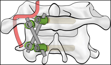
Unilateral C1 PAS + C2 LS combined with an ipsilateral crossed C1 + C2 PS–rod systems


Pullout strength test
After motion measurement, ten atlas vertebras were isolated via stripping of the remaining soft tissue and reoriented individually in custom-made molds using polymethylmethacrylate cement. The lateral mass and posterior tubercle of each vertebra were exposed (Fig. 3). Specimens were then placed in the materials testing machine (Material Testing System Inc., Minneapolis, MN) with their PS or PAS attached to a custom clamp (Fig. 4). The screw pullout test was performed along the axis of the screw at a loading rate of 2 mm/min until an abrupt change in the curve slope of the loading displacement was noted. The axial pullout force was defined as the peak load-to-failure.

Atlas vertebra with PS or PAS was embedded in custom-made molds using polymethylmethacrylate cement

Pullout strength test. a Measurement of PS. b Measurement of PAS
Statistical analysis
The results were presented as the mean ± SD. Statistical analyses were performed with Wilcoxon paired t test. Statistically significant differences were established at P < 0.05. Analyses were performed with SPSS Statistics, version 17.0 (SPSS Inc., Chicago, Illinois).
Results
ROM of the specimens in intact, destabilization, and stabilization conditions after different fixations is summarized in Fig. 5 and Table 1. The average ROM in intact conditions was 12.42° ± 1.96° in flexion, 10.27° ± 1.20° in extension, 9.82° ± 1.17° in total lateral bending, and 75.17° ± 4.76° in total axial rotation. Biomechanical results showed that the ROM in destabilization group significantly increased in all directions, compared with the intact conditions (P < 0.05 in all sub groups). However, after unilateral C1–C2 PS–rod fixation (Group A), the ROM of C1–C2 significantly decreased compared with both intact and destabilization groups in all directions (P < 0.05 in all sub groups), indicating a reduction in C1–C2 flexibility which was caused by soft-tissue stripping and odontoidectomy.

Range of motion (ROM, mean ± SD) of the C1–C2 segment in all directions under 1.5 Nm at a rate of 0.1 Nm/s. LLB left lateral bending, RLB right lateral bending, LAR left axial rotation, RAR right axial rotation
As predicted, bilateral C1–C2 PS–rod fixation (Group B) could provide a better stability for C1–C2 segment than unilateral C1–C2 PS–rod fixation after destabilization in both flexion–extension and axial rotation aspects (P < 0.05 in all sub groups). However, no statistical difference was observed in further comparisons among Group B, Group C, and Group D (P > 0.05 in all sub groups), suggesting a possible of equal biomechanical efficacy among these three fixation methods.
Data from pullout strength test (Table 2) showed that the pullout strength of PS and PAS was 585 ± 53 and 463 ± 49 N, respectively. Although PS strength was a bit better than the PAS (P = 0.009), both PS and PAS could provide high fixed strength for C1–C2 segment.
Discussion
The atlantoaxial complex plays an essential role in ensuring cervical movements during daily life, including flexion, extension, lateral bending, and rotation. Atlantoaxial instability not only affects the quality of life, but also leads to severe pain, neurologic damage, and even death. Only few patients can receive good recovery with non-surgical treatment. Therefore, surgical intervention is always very necessary for treating atlantoaxial instability via creating C1–C2 stabilization, minimizing motion and achieving solid intervertebral fusion [12].
Various fixation techniques have been invented to treat atlantoaxial instability. Wiring fixation (Gallie and Brooks techniques) was the first one to introduce. Although it was technically easy, it required extra bone graft and caused high risk of spinal cord injury. The rate of failure or nonunion was approximately 10–15% due to poor bending stability; thus, additional external stabilization after operation was usually needed [13]. Another representative method in the early days was transarticular screws (Magerl technique). It provided better control of bending and rotation instead of flexion–extension. In addition, this method was technically demanding and not suitable for screw placement on one side due to high variation rate (23%) and numerous incidences of VA injury [14]. The C1 LMS was also a common method for C1 fixation but with high technical demand. Modifications were introduced later to replace C1 LMS with C1 PS and positive clinical outcomes were reported in conjunction with the use of C2 PS [10]. Furthermore, this screw–rod fixation had reduced the risk of VA injury [15] and its biomechanical stability was equivalent to that of transarticular screws [16]. However, the application of C1 PS still had the risk of VA injury due to the special entry point on posterior arch.
There is always the potential risk for neurovascular injuries, especially VA bleeding, during the upper cervical surgery. This is attributed to the complexity of anatomy around the atlas, such as VA variation, large venous plexus, and congenital narrowing of cervical pedicle [17]. Troublesome bleeding not only extends operative time, but also may cause severe impairment of multiple organs or even death [18,19,20]. Thus, Some authors recommended that the vascular structures around the C1–C2 should be evaluated preoperatively using computerized tomography reconstruction, CT angiogram, or magnetic resonance imaging to fully understand the anatomical variations [21, 22].
C2 LS showed an equivalent stability as C1 LMS via biomechanical analysis without obvious risk of VA injury [23]. In addition, Miyakoshi et al. [24] reported that unilateral C2 PS + LS could be comparable with bilateral C2 PS fixation through clinical observation. It indicated that C2 PS + LS could be a good alternative of C2 PS in clinical practice which had relatively low risk of VA injury [25]. C1 PAS, described by Floyd and Grob during C1–C2 fixation, was another recommended surgical technique for clinical practice [26]. Excellent outcomes had been obtained via biomechanical study and clinical application [27]. Moreover, the screw path of both PAS and LS could be directly visualized; thus, the use of C1 PAS and C2 LS might avoid the risk of VA injury. Jin et al. had recently reported an excellent biomechanical result of unilateral C1 PAS and C2 LS combined with one-side C1–C2 PS for posterior C1–C2 fixation [28]. It is generally thought that crossed screws could increase the lengths of the screws, as well as provide decortication and arthrodesis. Therefore, we designed a new unilateral C1 PAS and C2 LS combined with an ipsilateral crossed C1–C2 PS–rod fixation technique (Group D) and compared it with other fixation methods via biomechanical evaluations. In our study, bilateral C1 + C2 PS–rod systems (Group B) were considered to be the golden standard for biomechanical evaluations as described [24]. Besides, the recent study reported an efficient fixation method by Jin et al. (Group C) had also been added as reference standard.
As expected, our new method could provide instant stability in all directions for C1–C2 segment after destabilization and was even better than the intact condition (Fig. 5; Table 1). When comparing with unilateral C1–C2 PS–rod fixation (Group A), our new method significantly decreased the ROM of C1–C2 segment, indicating a better clinical expectation. The biomechanical study also found that our hybrid design of PAS + LS + PS fixation could provide the same stability as the bilateral C1 + C2 PS–rod systems and the recent efficient fixation method reported by Jin et al. The equal biomechanical efficacy among these three fixation methods was proved in our study (Fig. 5; Table 1). In addition, our data from pullout strength test indicated that the fixation strength of PS was significant higher than that of PAS (Table 2). We thought that there were two reasons leading to higher pullout strength of C1 including asymmetry forces of C1 PAS caused by the arc structures of C1 posterior arch and higher BMD of C1 lateral mass due to its weight-bearing property. However, we thought that the fixation strength of PAS was also high enough (463 ± 49 N) for providing the rigid stability. Therefore, our new method of unilateral C1 PAS and C2 LS combined with an ipsilateral crossed C1–C2 PS–rod fixation had met both requirements of unilateral fixation and a good stability.
Although our study showed positive biomechanical results, several limitations must be considered. This method causes extensive injury of the neck musculature, and improvements in surgical navigation and minimal invasive are expected. Besides, the number of specimens enrolled in the study was small and the clinical evidence was also lack. Therefore, conclusions based on the outcome are preliminary.
Conclusion
The surgical technique of unilateral C1 PAS + C2 LS combined with a crossed C1–C2 PS–rod fixation provided a better stability than the traditional unilateral PS–rod fixation and a same stability as bilateral PS–rod fixation, but with less risk of neurovascular injury. According to our results, this new surgical technique may constitute an alternative method for the treatment of atlantoaxial instability.
References
Bisson E, Schiffern A, Daubs MD, Brodke DS, Patel AA (2010) Combined occipital-cervical and atlantoaxial disassociation without neurologic injury case report and review of the literature. Spine 35:E316–E321. doi:10.1097/BRS.0b013e3181c41d2c
Nightingale RW, Winkelstein BA, Knaub KE, Richardson WJ, Luck JF, Myers BS (2002) Comparative strengths and structural properties of the upper and lower cervical spine in flexion and extension. J Biomech 35:725–732
Gautschi OP, Payer M, Corniola MV, Smoll NR, Schaller K, Tessitore E (2014) Clinically relevant complications related to posterior atlanto-axial fixation in atlanto-axial instability and their management. Clin Neurol Neurosurg 123:131–135. doi:10.1016/j.clineuro.2014.05.020 (Epub 2014 Jun 4)
Tessitore E, Bartoli A, Schaller K, Payer M (2011) Accuracy of freehand uoroscopy-guided placement of C1 lateral mass and C2 isthmic screws in atlanto-axial instability. Acta Neurochir (Wien) 153:1417–1425. doi:10.1007/s00701-011-1039-9 (discussion 1425. Epub 2011 May 21)
Grob D, Crisco JJ III, Panjabi MM, Wang P, Dvorak J (1992) Biomechanical evaluation of four different posterior atlantoaxial fixation techniques. Spine 17:480–490
Henriques T, Cunningham BW, Olerud C, Shimamoto N, Lee GA, Larsson S, McAfee PA (2000) Biomechanical comparison of five different atlantoaxial posterior fixation techniques. Spine 25:2877–2883
Kandziora F, Kerschbaumer F, Starker M, Mittlmeier T (2000) Biomechanical assessment of transoral plate fixation for atlantoaxial instability. Spine 25:1555–1561
Kandziora F, Pflugmacher R, Ludwig K, Duda G, Mittlmeier T, Haas NP (2002) Biomechanical comparison of four anterior atlantoaxial plate systems. J Neurosurg 96:313–320
Huang DG, Hao DJ, He BR, Wu QN, Liu TJ, Wang XD, Guo H, Fang XY (2015) Posterior atlantoaxial fixation: a review of all techniques. Spine J 15:2271–2281
Harms J, Melcher RP (2001) Posterior C1–C2 fusion with polyaxial screw and rod fixation. Spine 26:2467–2471
Li S, Ni B, Xie N, Wang M, Guo X, Zhang F, Wang J, Zhao W (2010) Biomechanical evaluation of an atlantoaxial lateral mass fusion cage with C1–C2 pedicle fixation. Spine 35:E624–E632. doi:10.1097/BRS.0b013e3181cf412b
Ferguson RL, Tencer AF, Woodard P, Allen BL Jr (1988) Biomechanical comparisons of spinal fracture models and the stabilizing effects of posterior instrumentations. Spine 13:453–460
Dickman CA, Sonntag VK (1998) Posterior C1–C2 transarticular screw fixation for atlantoaxial arthrodesis. Neurosurgery 43:275–280
Madawi A, Solanki G, Casey AT, Crockard HA (1997) Variation of the groove in the axis vertebra for the vertebral artery: implications for instrumentation. J Bone Joint Surg Br 79:820–823
Abumi K, Takada T, Shono Y, Kaneda K, Fujiya M (1999) Posterior occipitocervical reconstruction using cervical pedicle screws and plate-rod systems. Spine 24:1425–1434
Kuroki H, Rengachary SS, Goel VK, Holekamp SA, Pitkanen V, Ebraheim NA (2005) Biomechanical comparison of two stabilization techniques of the atlantoaxial joints: transarticular screw fixation versus screw and rod fixation. Neurosurgery 56:151–159 (discussion 151–159)
Claybrooks R, Kayanja M, Milks R, Benzel E (2007) Atlantoaxial fusion: a biomechanical analysis of two C1–C2 fusion techniques. Spine J 7:682–688
Pan J, Li L, Qian L, Tan J, Sun G, Li X (2010) C1 lateral mass screw insertion with protection of C1-C2 venous sinus. Spine 35:E1133–E1136. doi:10.1097/BRS.0b013e3181e215ff
Aota Y, Honda A, Uesugi M, Yamashita T, Baba N, Niwa T, Saito T (2006) Vertebral artery injury in C-1 lateral mass screw fixation. Case illustration. J Neurosurg Spine 5:554
Rocha R, Safavi-Abbasi S, Reis C, Theodore N, Bambakidis N, de Oliveira E, Sonntag VK, Crawford NR (2007) Working area, safety zones, and angles of approach for posterior C-1 lateral mass screw placement: a quantitative anatomical and morphometric evaluation. J Neurosurg Spine 6:247–254
Paramore CG, Dickman CA, Sonntag VKH (1996) The anatomical suitability of the C1–C2 complex for transarticular screw fixation. J Neurosurg 85:221–224
Fujii T, Oda T, Kato Y, Fujita S, Tanaka M (2000) Accuracy of atlantoaxial transartivular screw fixaion. Spine 25:1760–1764
Lehman RA, Dmitriev AE, Helgeson MD, Sasso RC, Kuklo TR, Riew KD (2008) Salvage of C2 pedicle and pars screws using the intralaminar technique: a biomechanical analysis. Spine 33:960–965. doi:10.1097/BRS.0b013e31816c915b
Miyakoshi N, Hongo M, Kobayashi T, Suzuki T, Abe E, Shimada Y (2014) Comparison between bilateral C2 pedicle screwing and unilateral C2 pedicle screwing, combined with contralateral C2 laminar screwing, for atlantoaxial posterior fixation. Asian Spine J 8:777–785. doi:10.4184/asj.2014.8.6.777 (Epub 2014 Dec 17)
Meyer D, Meyer F, Kretschmer T, Börm W (2012) Translaminar screws of the axis–an alternative technique for rigid screw fixation in upper cervical spine instability. Neurosurg Rev 35:255–261. doi:10.1007/s10143-011-0358-x (discussion 261. Epub 2011 Nov 17)
Floyd T, Grob D (2000) Translaminar screws in the atlas. Spine 25:2913–2915
Donnellan MB, Sergides IG, Sears WR (2008) Atlantoaxial stabilization using multiaxial C-1 posterior arch screws. J Neurosurg Spine 9:522–527. doi:10.3171/SPI.2008.10.08294
Jin GX, Wang H (2016) Unilateral C-1 posterior arch screws and C-2 laminar screws combined with a 1-side C1–2 pedicle screw system as salvage fixation for atlantoaxial instability. J Neurosurg Spine 24:315–320
Acknowledgements
The Key Project of Medical scientific research of Chongqing health and family planning commission (no. 2016ZDXM007), the special foundation for scientific research platform of Chongqing (no. ctsc2015yfpt-gcjsyjzx120019) funds were received in support of this work.
Author information
Authors and Affiliations
Corresponding author
Ethics declarations
Conflict of interest
Kai Shen, Zhong-Liang Deng, Jun-Song Yang, Chao Liu, and Ran-Xi Zhang have no conflicts of interest.
Rights and permissions
About this article

Cite this article
Shen, K., Deng, Z., Yang, J. et al. Biomechanical study of novel unilateral C1 posterior arch screws and C2 laminar screws combined with an ipsilateral crossed C1–C2 pedicle screw–rod fixation for atlantoaxial instability. Arch Orthop Trauma Surg 137, 1349–1355 (2017). https://doi.org/10.1007/s00402-017-2781-0
Received:
Published:
Issue Date:
DOI: https://doi.org/10.1007/s00402-017-2781-0