
Abstract
All over the world, environmental considerations are now becoming vital factors during the selection of consumer goods which include textiles. According to the World Bank, 20% of water pollution globally is caused by textile processing, which means that these industries produce vast amounts of wastewater. Generally, these effluents contain high levels of suspended solids (SS), phosphates, dyes, salts, organo-pesticides, non-biodegradable organics, and heavy metals. Increase in water scarcity and environmental regulations has led to textile industries to seek for sustainable wastewater treatment methods which help to reduce their water footprint as well as reduce their operational costs. Therefore, sustainable wastewater treatment could be the best choice for the textile industries with respect to the current issues. So, it is important to discuss and champion awareness mechanisms which help to reduce the current issues with respect to the textile wastewater. Therefore, this chapter intends to discuss the various sustainable wastewater treatments, namely granular activated carbon (GAC), electrocoagulation (EC), ultrasonic treatment, an advanced oxidation process (AOP), ozonation, membrane biological reactor (MBR), and sequencing batch reactor (SBR).
Access provided by CONRICYT-eBooks. Download chapter PDF
Keywords
- Wastewater
- Effluent
- Textile industry
- Electrocoagulation
- Water pollution
- Pollution
- Membrane bioreactor
- Ultrafiltration
- Activated carbon and sustainability
1 Introduction
Among all planets in the solar system, the earth is notably a unique planet because of the life-supporting conditions present. Life forms of various nature, from microorganisms to human beings, dwell on earth. The environment that supports life and sustains various human activities is generally known as the biosphere. The term “environment” means surroundings. It is defined as “the sum of all social, economic, biological, physical, or chemical factors which constitute the surroundings of man whose task is to govern the environment.” The biosphere is a shallow layer compared to the total size of earth and extends to about 20 km from the bottom of the ocean, the highest point in the atmosphere at which life can survive, without man-made protective devices. Man’s habitation of the earth and his activities such as agricultural and industrial revolutions followed by the current high-tech world of synthetic and man-made materials have had a negative impact on the environment and biodiversity. Some the major impacts of man on the environment are discussed briefly below. Reduced child mortalities and developments in medicines had increased the lifespan of humans. The birthrate/m is 2–3 times higher than the death rates; with these rates, by 2050, the world’s population is expected to be around 9.8 billion compared to the current level of 7.6 billion [1]. This population stress leads to increase land habitation and demands, on resources like water, minerals, fossil fuels, and food, etc., all at the cost of major environmental degradation. Ongoing depletion of ground and surface waters, natural wealth, fossil fuels, forests, greenery and species diversity, due to overconsumption habits of human, is a permanent threat posed by humanity and the environment. There is rapid increase in deforestation which eventually leads to soil erosion, loss of plants and niche to other species, global warming and climatic changes. Deforestation, hunting, urbanization, and agricultural land reformation lead to the extinction and deprive the habitat to a vast variety of species, leading to endangered species and animals. However each and every biotic element has a role in nature’s harmony, the ongoing loss of biodiversity is a threat to natural ecosystems. The massive urbanization brings in the need for housing, utilities, buildings, industries, roads, transportation, infrastructures, water, and energy supplies. All this is attained at the cost of deforestation and loss of greenery. The end results are congestion, water, energy demands, pollution issues, and loss of biodiversity. Overconsumption of water for domestic, agricultural, and industrial needs ends in contamination of water sources, surface and groundwater depletion, and degradation. Water, a major abiotic element for support of life, is rendered useless for consumption by way of organic, mineral, toxic, bacterial, and physical pollutions. Water pollution is an alteration of physical, chemical, and biological properties of water in a water body, rendering it unsuitable for consumption. Water pollution renders it unsafe for human or animal consumption, for industry, aquaculture and agriculture or recreation leading to land, thermal, and marine pollution. The need for energy for domestic, transport, and industrial operations has, for instance, led to combustion of fossil fuels in due process delivering pollutant greenhouse gases like carbon monoxide, carbon dioxide, nitrogen, sulfur, and carbon particles and add to the air temperature. Industrial emissions and chlorinated products also add potential contaminants into the atmosphere, the end results being acid rains, global warming, air toxicity, climatic change, and depletion of ozone layer. Deforestation and urbanization are the major causes of land abuse and soil erosion in due course leading to loss of fertility, contamination of pollutants—solid and liquid wastes on to land. The industrial revolution led to the birth of various industries, among them the textile industry. Textile industries have two divisions:
-
Dry process—mostly engineering and assembling departments, which do not use water for all practical purpose (e.g., blowroom, carding, weaving).
-
Wet process—departments which use water as raw material or in their processes or for both (e.g., chemical processing like coloration, printing, garment washing).
A couple of countries has the largest share of their gross domestic product (GDP) coming from textile and apparel industries; however, a hasty and unplanned clustered growth of these industries in most cases has environmental concerns. This chapter aims to present environmental challenges in textile industries and importance of sustainable wastewater treatment. Furthermore, it includes the comprehensive discussion of various conventional effluent treatments as well as its pros and cons as compared to various sustainable wastewater treatments, namely granular activated carbon (GAC), electrocoagulation (EC), ultrasonic treatment, advanced oxidation process (AOP) such as ozonation, membrane biological reactor (MBR), sequencing batch reactor (SBR), and rotating biological contactor (RBC). This chapter merely attempts to discuss the various sustainable wastewater treatments in textile industry, namely GAC, EC, ultrasonic treatment, AOP, ozonation, MBR, and SBR. This treatment could be a best choice for the textile industries with respect to the current environmental issues. Generally, the conventional wastewater treatments not only increase the landfill and extensive infrastructure needs, but also it changes the ecosystem when the landfill is not properly managed. In addition, these technologies consume considerable energy, which consequently emit the carbon emission. However, sustainable wastewater treatments provide significantly increased pollutant removal efficiency, and considerably reduce the sludge management, energy consumption, and running cost. In this process sequence, biologically based treatments offer high organic removal efficiency and adverse impact on the ecosystem, and also it ensures the sustainable sludge management which consume less energy; therefore, it reduces the overall cost.
2 Water Pollution Associated with Textile Industries
The coloration of textile involves a group of dyes, namely acid, direct, reactive, metal: complex, vat, sulfur, disperse and pigment. Generally, colorants are complex of organic or inorganic chemicals, and it can be applied to textile with different methods; however, the dye exhaustion is varied from 50 to 85%; therefore, dyes will discharge in the effluent as a pollutant, which badly affects the nearby water streams (Fig. 1). The color of dye wastewater changes the color of entire pollutant; however, it looks brownish red, black, or a mixture of both, and it also contains 4000–5000 parts per million (ppm) of SS [2,3,4,5]. Apart from a colorant, huge quantity of chemicals and auxiliaries are used during wet processing; in addition to process water, large volumes of cooling water are discharged as waste [6,7,8,9,10]. Apart from these effluents, solid wastes and liquid wastes as effluent are also discharged on land or into sewers or into natural water resources. The various effluents which are generated from textile chemical processing are given in Table 1, and the domestic standards for effluent discharge are given in Table 2. The effluent discharge standards for Indian textile industry are given in Table 3.

Textile effluent contaminates of Noyyal River at Tirupur, India
2.1 Effluent Discharged Various Operation of Textile Process
Melt and dry spinning operations produce not much effluent as compared to wet spinning [13]; however, wet spinning, for example, of viscose rayon produces huge pollutant in the wastewaters [14]. Table 4 shows the possible pollutant which caused by wet spinning and dry spinning. The basic steps involved in viscose rayon manufacture are wood pulping, soda cellulose formation and molecular fragmentation, solubilization with carbon disulfide, blending, wet spinning, washing, and finishing [15].
As discussed earlier, chemical/wet processing of textile industry alone contributes 70% of the pollution. It is well known that textile wet processing consumes large amount of water for a various processes like sizing, desizing, scouring, bleaching, dyeing, printing, finishing, and other treatments (Fig. 2); further still, the different chemicals utilized lead to an acidic pH (Tables 5 and 6), and eventually, a large quantity of wastewater is discharged as a pollutant, which enormously spoils the water streams (Table 7).

Percentage share of water consumption in chemical processing of cotton materials
Manufacturing of dyes and pigments deals with aromatic hydrocarbons amines, mineral acids like sulfuric and nitric acids and also involves a chain of reactions like starting toxic raw materials, intermediate steps like diazotization, coupling, sulfonation, nitration, etc.
The effluent from the dye industry is of high organic content, colored, and of high COD/BOD values. The dye and pigment industrial wastewaters are composed of insoluble organic pigments, dyes, heavy metals, emulsifiers which are shown in Table 8.
3 Effluent Treatment Process
Wastewater from the textile industry is the main source of the organic contamination, which causes hemorrhage, ulceration of skin, nausea, skin irritation, and dermatitis. The contamination present in the effluent can block the sunlight and increase the BOD, therefore preventing photosynthesis and reoxygenation process. Various processes need to be implemented so as to reduce the pollution load; in this case, many physical methods (adsorption, filtration methods, coagulation, and flocculation processes), chemical methods (oxidation, advanced oxidation, Fenton’s reagent), and biological treatment (anaerobic, aerobic) are carried out. The whole effluent process involves three steps (Fig. 3), namely primary treatment, secondary treatment, and tertiary treatment. In general, the primary treatments involve removal of the SS, floating and gritty materials, the secondary treatment involves reduction of oxygen demands, other chemicals, and color of pollutant, and lastly, the tertiary treatment involves the removal of the final contaminates left over in the pollutant. After the treatments, treated water must be analyzed for the quality so as to gage its reuse or discharge into the water streams [23,24,25].

Wastewater techniques for textile wet processing industries
Sustainable Wastewater Treatment and Overview of Existing Color Removal Methods
As discussed earlier, water and land is vital but is a limited resource, and it should not be polluted as a result of the industrial process. Therefore, the main task for the emerging technologies is to protect the earth from the pollution of industrial processes. In the present scenario, the conventional effluent treatment discharges huge quantities of sludge, which is an unwanted residue; perhaps sludge management is critical with respect to the environmental issues [23, 24, 26,27,28]. Sludge eventually ends up in landfills; however, it is not a safe practice since it leads to the pollution of air, water, and soil, also generates the uncontrolled landfill gases like methane, CO2, and volatile organic carbons were proceed to global warming. During the landfilling, there is a huge possibility to contaminate the local groundwater due to the leaching potential [29]. Groundwater contamination from sludge is also an environmental concern and, therefore, quest for an alternative technology that can reduce the sludge during the effluent treatment is a step in the positive direction. In this case, chemical coagulation and other conventional effluent treatment process contribute significant impact on the sludge formation; therefore, it is advised to replace by electrocoagulation (EC) process. The colored water from textile effluent could be the biggest threat to the environment, and there are 12 classes of chromogenic groups, but azo and anthraquinone types are mostly used in the textile industry; both classes contribute 80% of total dye contributing to the textile colorants. On average, the dye house effluent contains 0.6–0.8 g dye 1−1 [30], hence the color and dye removal in the effluent becomes more important and it is a major scientific interest. In order to remove the colors from textile wastewater, various methods are used, such as chemical oxidation, coagulation and flocculation, membrane separation, aerobic and anaerobic degradation.
As there are some limitations such as the excess amount of chemical usage, accumulation of concentrated sludge that has serious disposal problems and lack of effective color reduction in some of these techniques, it has been shown to be effective. Based on the transfer of pollutants from the solution to the solid phase, it is known as the adsorption technique which is one of the efficient and general wastewater treatment methods. In terms of the initial cost, the simplicity of design, ease of operation, and non-toxicity of the utilized adsorbents, the adsorption method is superior to other dye removal techniques such as conventional wastewater treatment methods [31]. In selecting the absorbent to remove organic compounds from wastewaters [31, 32], the main criteria are the cost-effectiveness, availability, and adsorptive properties and especially non-toxic and green adsorbent-based application of adsorption procedure with high surface area, and the reactive surface atom is a great demand [33, 34]. The existing process and alternative process are given in Table 9.
3.1 Primary Treatments
The purpose of primary treatment is to remove insoluble, invisible, and colloidal organic color and SS, and this treatment involves screening, equalization, neutralization, and coagulation followed by sedimentation steps. Primary reductions of COD and BOD value are also enhanced by this treatment. Various steps of primary treatment are as follows:
-
Screening
This process can remove the floating and suspended materials, and screens of various sizes and shapes are used depending on the nature of solids to be removed. Generally, fixed bar screens are the most used. Other simple screening equipment is mix mesh frames, alternate perforated plate frames, or damper plate with specific spacing. The screenings are disposed of by various methods such as grid, incineration, grinding, and digestion.
-
Equalization
The textile effluent has the difference in characteristics like color, turbidity, pH, BOD, COD, TDS, etc. Prior to the primary treatment, it is necessary to proportionately mix various process water to get together to achieve a uniform character. Equalization helps in providing such uniform effluent and prevents shock loads and sudden increase or decrease in pH due to some textile processes like mercerizing, scouring, carbonizing effluents entering the plant suddenly. Also, this process improves the dissolved oxygen (DO) levels.
-
Neutralization
Most of the secondary biological treatments are effective only if the pH value of effluent is between 6 and 9. However, extreme pH conditions make ineffective secondary treatments, since digestive bacteria can survive close to neutral pH conditions and are dead at extreme pH. Therefore, it is necessary to adjust the pH in the range of 6–9. Depending on the situations, dosing at regular uniform rate should be done from the stored tanks containing the above liquors. Sometimes it becomes necessary to add dilute H2SO4 or CO2 as per need.
-
Coagulation sedimentation
Coagulation sedimentation is one of the most used methods, especially in the conventional effluent treatment process. However, the action on the suspended matter, the colloidal type of very small size, and their electrical charge give repulsion and prevent their aggregation. In this case, add the electrolytic products (aluminum sulfates, ferric sulfates, ferric chloride) which can eliminate the surface electrical charge of the colloids. As per the environmental concerns, electrocoagulation can replace this process since it is not environmentally friendly.
3.2 Secondary Treatment Process
Presence of soluble organics, toxic metals, and organics may increase the BOD/COD values of effluent. The aim of secondary treatment is digestion of soluble organics by bacteria (aerobic or anaerobic mode), which improves the DO content, therefore resulting in reduced BOD/COD levels (80–85%) and toxicity. So, this process is enhanced by proper pH control (close to neutral), feeding of nutrients, prolonged interaction with air/oxygen, etc.
-
Aerobic
Aerobic biological treatment (oxidation) is carried out in the presence of air (open condition), so the soluble organics get converted into CO2 and it could be removed out of effluent. Anaerobic biological treatment (treatment) is carried out under closed conditions in the absence of air; here, organic materials get converted into CH4 or ammonia and are released out of effluent.
-
Activated sludge process
In this method, effluents were continuously exposed and subjected to biological degradation carried out by “microbial floc” suspended in the reaction tank, where the oxygen is introduced mechanical manner. The flocks formed in activated sludge process (ASP) are “zoology masses of living organism” embedded with food and slime material and are active centers of biological oxidation and therefore the name activated sludge process. A number of bacteria to be added depend on the organic matter present in the effluent to be treated.
3.3 Tertiary Treatment
The purpose of tertiary treatment is to remove dissolved solids (minerals, salts) from wastewater. The wastewater after efficient tertiary treatment can be safely discharged or reused for processing. The modern effluent treatment plants employ the following tertiary treatment operations to separate dissolved solids and recover pure/safe water for reuse.
3.3.1 Membrane Technology
The membrane is a thin section of a material which arranged in suitable configuration (sheet or roll form); generally, it acts as a phase separator which permeable to one or like components [35]. Membranes are usually made up of polymers like as cellulose acetate/cellulose, triacetate polyamide, polyester, polypropylene, etc. The pore size of the membrane is usually expressed in micrometer/nanometers [36]. There are different membrane systems that could be used in textile wastewater treatment; they are micro-, ultra-, nano-, and RO filtrations, and each one has different cleaning properties (Table 10).
3.3.1.1 Microfiltration
Microfiltration process is based on the membrane technology; it can remove the particles in the range of 0.1–0.2 μm. The principle of microfiltration is a physical separation. Substances that are larger than the pores in the membranes are fully removed, meanwhile substances with smaller than the pores of the membrane are partially removed [38, 39]. However, SS, bacteria, pigments, oils, and large particles are removed. Microfiltration rejects ranges up to 10%. Microfiltration membranes are made of several polymers including poly (ether sulfone). Poly(vinylidene fluoride) and poly (sulfone). Ceramic, carbon, and sintered metal membranes have been employed where extreme chemical resistance or high-temperature operation can be carried out [21, 40].
3.3.1.2 Ultrafiltration
Ultrafiltration utilizes membranes to remove usually in the range of 500–1000 molecular weight. Ultrafiltration is generally preceded by conventional filters or cartridge filters to prevent blinding of the membranes. Periodically, the membranes must be cleaned by backflush technique. Ultrafiltration is used to separate polymers from salts and low molecular weight materials, with pores of 0.001 m–0.1 µm. Turbidity is sharply reduced by 99%. Polymers are retained for reduced Total Oxygen Demand (TOD), BOD, and COD. It is an excellent filtration technique to remove metal hydroxides and heavy metal up to 1 ppm or even less [21, 36, 39].
3.3.1.3 Nanofiltration
Nanofiltration membrane works similar to reverse osmosis (RO) except for pressure (less pressure is required for nanofiltration, i.e., 70 and 140 psi); it is due to the larger membrane pore size (0.05–0.005 μm). Nanofiltration removes the dyes, pesticides, and divalent ions, and also it is capable of removing hardness elements such as calcium or magnesium together with bacteria, viruses, and color. However, it operated with lower pressure than RO; therefore, operating cost is less than RO process [21, 36, 38,39,40].
3.3.1.4 Reverse Osmosis
In RO process, the good water is separated from pollutant through a membrane with the help of osmotic pressure. However, the RO process may be reversed by applying a pressure on the brine side higher than the osmotic pressure. A series of tubes made up of porous material is lined on the inside with an extremely thin film of cellulose acetate semipermeable membrane. These tubes are arranged in a parallel array; brackish water is pumped continuously with high pressure (>25 atm) through these tubes, and due to the high pressure, only water can penetrate through membrane and salt and another pollutant cannot, since the size of the pore can allow only water. Concentrated brine (reject) and freshwater (permeate) are withdrawn through their respective outlets. Prior to RO filtration, wastewater should be treated with sand filtration, activated carbon (AC) filtration, microfiltration, ultrafiltration, and removals of iron/calcium are necessary for smooth functioning. Generally, RO rejects ranges from 40 to 50% which is further run into the second stage and third stage of RO to recover maximum freshwater [41, 42].
-
Activated carbon treatment
AC is composed of a microporous, homogenous structure with high surface area (one gram of it has a surface area of approximately 500 m2) and shows radiation stability which is widely used adsorbent in industrial processes. In the developing countries, the process for producing high-efficiency AC is not completely examined; moreover, there are several problems with the regeneration of used AC. Nowadays, there is a large curiosity in order to find inexpensive and effective alternatives to the existing commercial AC. When an effective and low-cost AC is explored effectively, it may contribute to environmental sustainability and offer benefits for future commercial applications. Comparatively, the costs of AC prepared from biomaterials are very low to that of the cost of commercial AC [43,44,45,46]. There are numerous studies which can be carried out to produce AC from waste materials, such as waste wood [47], bagasse [48], coir pith [49], coffee husk [50], pinecone [51], coconut shell [52], and coconut flowers [53]. AC is ordinarily used to adsorb natural organic compounds, taste and odor compounds, and synthetic organic chemicals in drinking water treatment. Both the physical and chemical process of accumulating a substance at the interface between liquid and solids phases is the adsorption. Due to the highly porous material and in providing a large surface area to which contaminants may adsorb, AC is an effective adsorbent. The two important types of AC utilized in water treatment applications are granular activated carbon (GAC) and powdered activated carbon (PAC). AC has the immense surface area and highly porous nature which allows the adsorbed compounds to penetrate the material fully, endeavoring out all available binding points. Chemical reactions also take place to change some offensive compounds into less objectionable variations. Even though the AC is not effective against all compounds, it does have the ability to bond with compounds in all three phases: liquid, solid, and gas.
-
Production
A wide variety of carbon-rich precursor materials such as bituminous coal, anthracite, sub-bituminous coal, lignite, wood, coconut shells, and peat are used to produce ACs. By either thermal or chemical activation processes, these materials are converted into AC. Steam gasification (activation) and chemical activation used reactive, inorganic additives at relatively lower temperatures and are typically included in thermal treatment. Bituminous coal can be classified as direct-activated or re-agglomerated to produce the ACs. Direct activation is involved to size the coal approximately to the required particle size and thermally activating the sized coal. Comparatively, direct activation can produce a less costly product to that of re-agglomeration. Re-agglomeration involves first pulverizing and briquetting the coal with organic binders. The desired particle size is achieved through the stage crushing the briquettes. The binder is also converted to a graphitic structure that interconnects the activated coal particles when the agglomerated material has been activated. Both the hardness and abrasion characteristics of re-agglomerated and direct-activated GAC are frequently comparable. In order to have a better certain organic contaminant removal, re-agglomerated carbons tend to have a more homogenous pore structure. All the carbonaceous raw material reacts during thermal treatment by means of condensation reactions to form increasingly larger aromatic plate structures. The characteristics of the raw materials influence the density of the structure. In order to have more extensive structures, the raw materials must be denser such as bituminous coal. Within the GAC particle, these outstretched flat graphite platelets are placed indiscriminately to provide the extensive internal structure needed for adsorption to occur. AC treatment effectively removes chlorine-phenols chlorinated hydrocarbons, surfactants’ color, and odor-producing substances from textile effluent. It can also substantially reduce harmful contaminants including heavy metals such as copper, lead, mercury, disinfection by-products. AC filters are positively charged that attract and trap many contaminants and prevent them from passing through the pores in AC filters can become plugged over time making them ineffective to remove any more contaminants. Thermal regeneration is generally used to reactivate the carbon by which the organics are evaporated out. In series when one is exhausted can be removed from service or column can be replaced. In parallel columns, both the beds become saturated simultaneously and both have to be replaced. AC can be added directly to the effluent, which eliminates needs of carbon adsorption beds. DuPont developed a process in which powdered AC is directly added to the aeration tanks [54,55,56].
-
Granular activated carbon
Granular activated carbon (GAC) is a particular formulation of AC, or activated charcoal. In ancient India, for drinking water filtration AC was used, and as a multi-use purifier in ancient Egypt. In modern day, in the early nineteenth century, it was introduced to Europe’s sugar refining industry. Organic materials with high carbon contents such as wood, lignite, and coal are used in making GAC. The essential feature that distinguishes GAC to PAC is its particle size. Depending on the material used and manufacturing process, GAC typically has a diameter ranging between 1.2 and 1.6 mm and an apparent density ranging between 25 and 31 lb/ft3. The bed density is about 10% less than the apparent density and is used to determine the amount of GAC required to fill a given size filter. To promote stratification after backwashing and minimize desorption and premature breakthrough, the uniformity coefficient of GAC is quite large, typically about 1.9, which results in mixing AC particles and adsorbed compounds with AC particles. A process is known as adsorption work through the preparations of AC. In absorption, like as a sponge soaking up water compounds are evenly distributed throughout the absorbent product. In creating a film, however in adsorption, the compounds bind only to the surface molecules and carbon molecules are naturally attractive. Therefore, they actively seek to bond to other molecules [57, 58].
Working
For locating a GAC treatment, there are two most common option units in water treatment plants, such as:
-
a.
Post-filtration-adsorption—after the conventional filtration process (post-filter contactors or adsorbers), the GAC unit is located,
-
b.
Filtration-adsorption—GAC replaces some or all of the filter media in a granular media filter.
Examples of these configurations are shown in Figs. 4 and 5, respectively. The GAC contactor receives the highest quality water in post-filtration applications, and thus, it has the only objective to remove the dissolved organic compounds. Adsorbers which are backwashed are usually unnecessary unless excessive biological growth occurs. By providing longer contact times than filter-adsorbers ensure the stipulates of most flexibility for handling GAC and for designing specific adsorption conditions.

Post-filtration-adsorption of granular activated carbon process

Filtration adsorption of granular activated carbon process
The filter-adsorber configuration uses the GAC for turbidity and solid removal from textile effluent, and biological stabilization in addition to dissolved organics removal. By replacing all or a portion of the granular media with GAC, the existing rapid sand filters can often be retrofitted for filtration-adsorption. Capital costs are reduced significantly by retrofitting existing high-rate granular media filters since no additional filter boxes, under-drains, and backwashing systems may be needed. Nevertheless, filter-adsorbers backwashed more frequently than post-filter-adsorbers (filter-adsorber units are backwashed about as frequently as conventional high-rate granular filters) since it has shorter filter run times and in addition, due to increased backwashing filter-adsorbers may incur greater carbon losses and may cost more to operate because carbon usage is less effective. In order to determine the required GAC contactor volume, the primary factors are the (i) breakthrough, (ii) empty bed contact time (EBCT), and (iii) design flow rate. The time when the concentration of a contaminant in the effluent of the GAC unit exceeds the treatment requirement is the breakthrough time. The GAC is exhausted and must be replaced/regenerated when the GAC effluent concentration is greater than the performance standard for over three consecutive days which is considered as a rule of thumb. The EBCT is calculated as the ratio of empty bed volume to that of flow rate through the carbon. By increasing the bed volume or reducing the flow rate through the filter, the longer EBCTs can be achieved. The amount of carbon to be contained in the adsorption units is defined by the EBCT and the design flow rate. Breakthrough and reducing the GAC replacement/regeneration frequency can be delayed by longer EBCT. Formerly the optimum EBCT is established, the carbon depth and adsorber volume can be determined. Typical EBCTs for water treatment applications range between 5 and 25 m. For GAC filters, the surface loading rate is the flow rate through a given area of GAC filter bed which is expressed in units of gpm/ft3. Surface loading rates for GAC filters typically range between 2 and 10 gpm/ft3. Highly adsorbable compounds which can be used in high surface loading rates are targeted for removal. The surface loading rate is not important when the mass transfer is controlled by the rate of adsorption as is the case for less-adsorbable compounds. The carbon usage rate (CUR) is used to determine the rate at which carbon will be consumed and how often carbon must be replaced/regenerated. By increasing, contact times improve with carbon treatment effectiveness. The percentage of carbon is increased by the deeper beds that are exhausted at breakthrough. After carefully evaluating the capital investment, the optimum bed depth and volume are typically selected and operating costs associated with reactivation frequency and contactor construction costs [59,60,61,62,63].
GAC contractors can be organized as either,
-
Downflow fixed beds,
-
Upflow fixed or expanded beds, or
-
Pulsed beds, with single or multiple adsorbers operated in series or in parallel.
Each unit is connected in series with downflow fixed beds in series with the first adsorber in order to acquire the highest contaminant loading and the last unit receiving the lightest contaminant load. From the first unit, carbon is removed for reactivation, with the next adsorber becoming the lead unit. For parallel downflow fixed beds, each unit acquires the same flow and contaminant load. In order to maximize the carbon usage, multiple contactors are frequently operated in a parallel-staggered mode in which each contactor is at a different stage of carbon exhaustion. Since effluent from each contactor is integrated, individual contactors can be controlled beyond breakthrough such that the blended flow still meets the treatment goal. To remove the SS, periodic bed expansion is permitted by the up flow expanded beds and allows using smaller carbon particles without significantly increasing the head loss. Removal of spent carbon occurs from the bottom of the bed while fresh carbon is added at the top without system shutdown in the pulsed bed adsorbers. A pulsed bed cannot be entirely washed-out, which prevents contaminant breakthrough in the effluent [59,60,61,62,63].
3.3.2 Evaporation
Evaporation is an important tertiary treatment process; in textile industry, evaporation is used to dehydrate the concentrated solutions (e.g., caustic recovery from mercerizer) and separate dissolved solids, dyes, water from dye bath, and the rejected water from nanofiltration and RO process can be separated through evaporation through vaporizing and condensing of pure water. In case of effluent treatment, the permeate from RO as well as condensate water from evaporator results in pure distilled/demineralized water which can reuse in various textile processing or boilers [64,65,66]. Textile effluent is usually evaporated by the following two options.
-
a.
Solar evaporation
-
b.
Mechanical evaporation
-
Solar evaporation
The saline effluent (concentrate dye bath, first wash, rejected from RO, nanofiltration) is let into the large surface area in the open tanks, called as solar ponds (0.5–0.75 m height). For continuous operation and retention, multiples of solar ponds are constructed which gets filled up on a daily basis. The wind flow and sunlight available during daytime evaporate the surface water, and vapors are taken into the atmosphere (Fig. 6). The dissolved solids or concentrated dehydrated mass gets settled at the bottom and is periodically removed. The sludge is usually taken for secured landfilling storage.
Fig. 6 
Solar evaporation plant used in small-scale textile coloration units in Tirupur, India

-
Advantages
-
Simple construction
-
No energy costs involved
-
No maintenance required
-
No skilled technicians are required
-
-
Disadvantages
-
Very slow rate of evaporation
-
Ineffective during raining seasons, low wind flows, cold climate, etc.
-
Calls for larger surface area
-
Chances of overflow contamination into groundwater in case of rain
-
The release of water vapor into atmosphere leads to lack of recovery of pure water back for recycling.
-
-
Mechanical evaporation
Mechanical evaporators are heated by steam condensing on metallic, cylindrical tubes. As steam condensates on the outside of the tube, the heat of condensation causes saline water slurry on the inside of the tubes of the cylinder to get boiled. A mechanical evaporation is a device used for desalination or separation of pure liquid from admixtures, dehydration of dilute solution for concentration, separation of pure water from effluent slurries. In textile effluent treatment, evaporators are used for direct evaporation or stagewise concentrating saline effluent called as multiple effect evaporation plant (MEEP) (dye bath, first wash, RO, or nanorejects) followed by fluid crystallizer to separate solid and water. Evaporators can be batch or continuous operation, and the configuration can be vertical or horizontal. MEEP is a vertical cell in which stainless steel tube could be mounted; however, some of the evaporators are working with falling liquid film theory. The tube is heated with through steam, in generally the concentrated liquid is collected in the bottom of the evaporator, which is sent to next stage of the evaporator, where the freshwater is added to the first stage of the evaporator. Meanwhile, steam could be applied to the first stage of the evaporator; the next stage of evaporator gets steam from previous one. During evaporation, the liquid is re-circulated till it gets desired concentration [67, 68]. The operating parameters for MEEP are given in Table 11,
Table 11 Operating conditions for typical multiple evaporation plant (adopted and modified from [37])
3.3.3 Electrocoagulation (EC)
Electrocoagulation was first proposed by Vik et al. [69]. It was designed for London sewage treatment plant. In 1909, Harries J. T received the USA patent for wastewater treatment by electrolysis using sacrificial electrodes made through aluminum and iron. Later, Matteson et al. [70] described the “Electro Coagulator” which can produce aluminum hydroxide from hydroxyl ions by using aluminum electrodes. Electrocoagulation (EC) is a well-established technology for the sustainable treatment of wastewater without the addition of chemicals such as Ferric, polyaluminum chloride (PAC). It is an electrochemical process which removes the SS, colloidal material, and metals, as well as other dissolved solids from the wastewater. Literally, the process called as “electrolysis” which breaks the substance by using of electricity; here direct current (DC) can be applied through to metal electrodes, and it starts reacting on an atomic level at the electrode–water interface from neutral, elemental state to charged state [71]. Thereafter, the charged metal atoms left the plate and enter into the water. Therefore, the electricity is applied to the electrodes to create the charged metal coagulant which bonds with dissolved contaminants, precipitates out of solution, organics adsorb to the precipitated solids, and solids agglomerate and separate, in another word electrical current destabilizes the SS allowing them to precipitate. Generally, the electrode is made from mild steel or aluminum which consume electrochemical reaction, therefore it should be replaced periodically [72]. The advantage of this process is that it generates less sludge than another conventional coagulation process such as a chemical method. Further, it is easy to dewatering the sludge, which drastically reduces the disposal cost. Also, it removes wide range of pollutant which includes heavy metals, suspended/colloidal solids, bacteria, BOD, COD, hydrocarbons, pesticides, and herbicides. Typical removal efficiency is around 95% and plus, and this process is good pre-treatment to membrane technologies where the high quality of water is required to reuse (Table 12). Presently, this process has gained attention due to its ability to treat large volume and for its low cost [73,74,75,76].
3.3.3.1 Mechanism of Electrolysis
In this process, coagulant can be generated due to the electrochemical reactions which produce the ions and help to remove the various kinds of pollutants either by chemical reaction and precipitation or by causing the colloidal materials to coalesce. The main processes are occurring during the electrochemical reaction is electrolysis which held in the electrodes, formation of coagulants in the aqueous phase, adsorption of soluble or colloidal pollutants on coagulants, and removal by sedimentation and floatation. The main chemical reaction in the electrodes is as follows;
The flocculation and coagulation in the EC technique have the advantage that it can be possible to remove the small colloidal particles, whereas in the conventional method it could not be. In addition, it reduces the sludge levels and also it is a very simple process, therefore easy to operate. The simple principle of electrolysis is shown in Figs. 7 and 8.

(reprinted from [85], with kind permission of Elsevier publications)
Simple principles of electrocoagulation process

Laboratory-scale electrocoagulation process
-
Mode of EC operation
The mode of EC operation can be divided into two categories, which is batch and continuous processes. A continuous process of EC can be operated under steady-state conditions, particularly with respect to the fixed pollutant concentration and effluent flow rate; however, it is perfectly matched with bulk quantity (i.e., for industrial) of effluent, whereas batch reactors are suited to laboratory and pilot plant scale applications. In a continuous process, it is very easy to control the operational parameters; therefore, it provides the better efficiency. The batch process is mostly time-dependent, and the coagulant is continuously generated by the reactor with the dissolution of anode. Therefore, anode can hydrolyze the pollutants, so the concentration of pollutant, coagulant, and pH can change time to time. The schematic representation of batch and continuous EC processes is given in Fig. 9.
Fig. 9 
(reprinted from [86], with the kind permission of Elsevier publications)
Schematic diagram of batch and continuous modes of operation

3.3.3.2 Impact of Various Operating Parameters
However, the efficiency of EC process can be depended on the various operational parameters such as conductivity of the solution, arrangement of electrode, electrode shape, type of power supply, pH of the solution, current density (CD), distance between the electrodes, agitation speed, electrolysis time, initial pollutant concentration, retention time, and passivation of the electrode [86].
-
Solution conductivity
In the electrolysis, solution conductivity is very important; however, removal efficiency and operational cost of EC process are based on the solution conductivity. In general, the solution must have minimum conductivity, and then only electric current could be flowing in the solution. However, the addition of electrolyte (sodium chloride or sodium sulfate) can regulate the conductivity of low-conductivity wastewater. Perhaps, the energy consumption could be less in case of higher conductivity solution [87].
-
Arrangement of electrodes
In EC process, the operational cost linearly depends on the connection mode of the electrode; however, it is confirmed by a previous study [88, 89]. Nasrullah et al. [89] studied the different arrangement of electrodes and their efficiency. Therefore, authors used to keep the electrodes in parallel, series, monopolar, and bipolar aluminum electrodes to find the optimum results. The arrangements (i.e., monopolar parallel (MP-P), monopolar series (MP-S), and bipolar (BP)) of the electrode can be described in the Fig. 10. The anode and cathodes are arranged in parallel order with respect to the MP-P setup; here the electric connection can be divided into the electrodes. In MP-S, electrodes are connected to the power source forming anode and cathode, while a pair of the inner electrodes (also called as sacrificial electrodes) is connected to each other without any connection to the power source. In BP configuration, there are two sacrificial electrodes which are placed in between the two parallel electrodes without any connection. Also, authors used different electrode orientation, namely vertical, horizontal orientation with anode at the bottom and horizontal orientation with anode on top; among these, vertical orientation provides higher percentage of COD removal, and it reached 59% with respect to the 120 m, whereas horizontal orientation with anode at the bottom shows only 40% of same time.
Fig. 10 
(reprinted from [89], with the kind permission of Elsevier publications)
Arrangement of electrode in EC process: a orientations, b arrangements
The results for the different arrangement of electrodes, MP-S showed 65, 65, and 60% for COD, BOD, and SS, respectively, in 120 m, whereas BP shows 56, 56, and 51%, which is lowest treatment efficiency toward to various pollution parameters (Fig. 11). It is clearly shown that the highest removal efficiency can get through serial connection than parallel connection. This is due to the higher consumption of anode material; therefore, the efficiency of pollutant treatment purely depends on the anodic dissolution in the system, where higher dissolution of anode makes more coagulants to the system, which assures more treatment efficiency.
Fig. 11 
(reprinted from [89], with the kind permission of Elsevier publications)
Effect of MP-S, MP-P, BP as electrode arrangements on a COD removal, b BOD removal, c SS, d anodic dissolution, and e current intensity changes during 120 m
-
Rotating anode
Ahmed Samir et al. [90] studied the overall efficiency of novel rotating electrodes with respect to the various speed and different CD on textile effluent (Imperon Violet KB (CAS #: 6358-46-9) for the fabric dyeing process.), schematic representation of rotating electrode are shown in Fig. 12.
Fig. 12 
(reprinted from [90], with kind permission of Elsevier publications)
a Schematic diagram of EC rotated anode system. b Details of EC rotated anode reactor: 1. motor variable speed; 2. stainless steel shaft; 3. upper Teflon flange cover; 4. Al rods of impellers anode; 5. Al rings of cathode; 6. Perspex reactor; 7. upper ports; 8. ball bearing; 9. thrust bearing; 10. lower port; 11. zoom coupling; 12. lower Teflon flange cover. c Top view of impellers anode with ring cathode


The overall results of total removal efficiency are shown in Fig. 13, COD removal efficiency is 90% when the anode was static with no rotational speed (CD = 8 mA/cm2) for the time period of 30 m, meanwhile the efficiency can be increased to 91% by increasing the rotational speed of electrode by 75 rpm and reduced the CD = 4 mA/cm2 for the time period of 10 m; similarly, the efficiency can be increased to 95% by increasing the rotational speed of 150 rpm with the same CD, and during this period, the formation of Al(OH)3 flocs which connected to other pollutants makes precipitation easier. But when the electrode speed is increased to 250 rpm, there is no COD removal efficiency can be achieved, which is due to the extremely high speed of the electrode cannot make the electrolysis process. In general, COD removal efficiency was increased by increasing the CD. The initial color and TSS were decreased within 10 m with the rotational speed of 150 rpm, and the results were significantly varied with respect to the CD; however, very good color removal can be obtained by application of 8 mA/cm2.

(reprinted from [90], with the kind permission of Elsevier publications)
a Effect of rotational speed on COD removal, I. CD = 4 mA/cm2; II. CD = 6 mA/cm2; III. CD = 8 mA/cm2; IV. Zero rotational speed. b Effect of rotational speed on TSS removal, I. CD = 4 mA/cm2; II. CD = 6 mA/cm2; III. CD = 8 mA/cm2; IV. Zero rotational speed. c Effect of rotational speed on color removal, I. CD = 4 mA/cm2; II. CD = 6 mA/cm2; III. CD = 8 mA/cm2; IV. Zero rotational speed
-
Shapes of the electrode
In EC process, the shape of electrodes is directly influenced on the pollutant removal efficiency. Yosuke Kuroda et al. [91] studied on the different shape of electrodes with respect to their pollutant removal efficiency and concluded that the punched hole type of electrode shows higher removal efficiency than the electrode without punched holes (Fig. 14). However, there are very few studies conducted on and reported in this field [92]. Kuroda et al. [91] reported in their studies the higher discharge current for the electrode with punched holes. However, the higher discharge current is directly influenced by higher pollutant removal efficiency. Perhaps, it still required higher number of studies to establish this study.
Fig. 14 
(reprinted from [91], with the kind permission of Elsevier publications)
Different electrode shapes used in EC process
-
Type of power supply
In the EC process, the electrolysis reaction can be performed through electrode, and it required electric voltage; the majority of the research has used DC and few are in alternative current [93, 94]. However, the use of DC leads to corrosion formation on the electrode due to the metal oxidation during the EC process, and also the oxidation layer can be formed in the cathode and followed by it reduce the current flow between the cathode and anode, results are reduced pollutant removal efficiency. Subramaniyan et al. [95] have studied the effect of alternative current and DC on pollutant removal efficiency of cadmium from water by using the aluminum alloy as anode and cathode. They obtained improved results with respect to the alternative current (97.5%) than DC (96.2%) (Fig. 15), at 0.2 A/dm2 of CD with pH of 7, the results provide the information that alternative current will reduce the formation of corrosion in the electrode, which resulted in increased removal efficiency.
Fig. 15 
(reprinted from [95], with the kind permission of Elsevier publications)
Effect of pH of the electrolyte on the removal of cadmium. Conditions: an electrolyte concentration of 20 mg/l; a current density of 0.2 A/dm2; temperature of 303 K


Eyvaz [94] analyzed the effects of alternating current electrocoagulation on textile wastewater for dye removal, and wastewater containing disperse yellow 241 (DY) and reactive yellow 135 (RY) dyes. They obtained the results of dye removal efficiency which are plotted in Fig. 16; in overall the reactive dye (RY) shows lower removal efficiency than disperse dye (DY) in both the power (i.e., alternative current and DC). However, after 100 m, alternating current power supply shows higher removal efficiency for both the dyes, which means that increasing the operation time can increase the accumulation of dye residue causing passivization on cathode material.

(reprinted from [94], with the kind permission of Elsevier publications)
Effects of power supply type on dye removal in view of operation time
-
pH of the solution
In the process of electrocoagulation, the important operational parameter is the pH of the solution. For a particular pollutant, the efficiency of removing the maximum pollutant is obtained at an optimum solution pH. At a particular pH, the precipitation of a pollutant begins. The pH of the solution from the optimum pH either decreases or increases according to the decreasing the pollutant removal efficiency. The removal of hexavalent chromium from synthetic solution was studied by Verma et al. [96] using electrocoagulation and found that the pH of the solution has a significant effect on the Cr(VI) removal efficiency. At different pH of the synthetic solution, they performed the experiments and acquired the maximum chromium removal efficiency at the pH 4. They concluded that the synthetic solution pH increases after the EC process with an increase in the electrolysis time due to the generation of OH in the EC process.
Fajardo et al. [88] have studied the influence of initial pH, applied CD and initial dye concentration on the efficiency of EC process with respect to textile wastewater. To asses the pH influence, they used different pH (3, 6, and 9) by adjusting with H2SO4 or NaOH. The pollutant removal efficiency was calculated with respect to the time; there is a significant improvement in COD removal when the initial pH of pollutant at 3, meanwhile, pH 6 and 9 could not show much difference within 30 m, thereafter all pH shows almost similar results. However, after 120 m, pH 9 will give a better result than another pollutant. In the case of color removal, before 60 m, there is a huge difference in the efficiency and thereafter the results are almost nearer, which means there is no significant difference (Fig. 17).

(reprinted from [88], with the kind permission of Elsevier publications)
Effect of the initial pH on color (a) and COD (b) removals over time. Inset a: pH evolution over time. Operating conditions: j = 16 mA/cm2, 100 mg/L of Reactive Black 5, stirring rate = 800 rpm (batch system), and flow rate = 160 l/h (flow system) batch-stirred system (BS) versus recirculation flow system (FS)
-
Current density
In electrocoagulation, the important parameter, namely CD, determines the coagulant dosage rate, bubble production rate, size and growth of the flocs, and in turn, it affects the efficiency of the electrocoagulation. As the CD increases, the anode dissolution rate increases. As a result, it increases the number of metal hydroxide flocs resulting in the increase in pollutant removal efficiency. When the CD increases above the optimum CD, it does not result in an increase in the pollutant removal efficiency due to a sufficient number of metal hydroxide flocs are procurable for the sedimentation of the pollutant. Fajardo et al. [88] also studied the impact of applied CD (i.e., authors used 4 and 16 mA/cm2) on the color removal; the results are plotted in Fig. 18. However, the highest color removal efficiency of 97.1% was found with respect to the 16 mA/cm2 at the time period of 90 m. Conversely, 360 m was necessary to achieve similar decolorization percentage when 4 mA/cm2 was applied. Apart from that, the COD removal efficiency is not showing the significant difference with respect to the applied CD.
Fig. 18 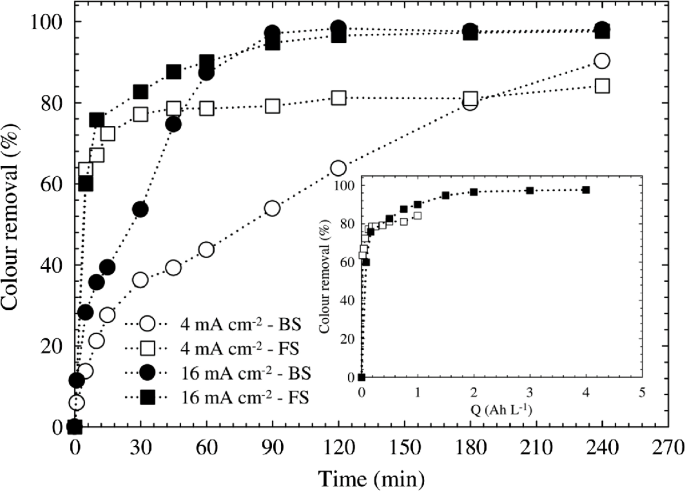
(reprinted from [88], with the kind permission of Elsevier publications)
Effect of the current density on color removal over time, for batch and flow systems. Inset: Color removal as a function of the applied charge at different current densities for the flow system. Operating conditions: pH = 6, 100 mg/L of Reactive Black 5, stirring rate = 800 rpm (batch system), and flow rate = 160 l/h (flow system)
-
Distance between the electrodes
The electrostatic field depends on the distance of anode and cathode; therefore, it plays a significant role in EC process. Maximum pollutant removal efficiency could be found with at optimum distance of anode and cathode. Perhaps, pollutant removal efficiency is less when the electrode distance is minimum; it is due to the metal hydroxides generated and followed by flocs, which refuse to sediment. Daneshvar et al. [82] studied the effect of interelectrode distance and their pollutant removal efficiency of Acid Red 14 dye. The result is shown in Fig. 19; color removal efficiency can be increased with increasing the distance of interelectrode (anode and cathode). This is due to the electrostatic effects between the interelectrode during the EC process; therefore, the distance increases, movement of produced ions could be slow in the action and possible to aggregate and produce the flocs.
Fig. 19 
(reprinted from [82], with the kind permission of Elsevier publications)
Effect of interelectrode distance on the efficiency of color removal from a solution
-
Effect of agitation speed
In order to maintain uniform conditions, the agitation is helpful and it avoids the formation of the concentration gradient in the electrolysis cell. Further, for the movement of the generated ions, the agitation in the electrolysis cell imparts velocity. In order to increase the pollutant removal efficiency, the agitation speed is increased up to the optimum agitation speed. For a particular electrolysis time, the flocs are formed much earlier which consequently increase the pollutant removal efficiency due to the fact that with an increase in the mobility of the generated ions. But there is a decrease in the pollutant removal efficiency when it is increased further in the agitation speed beyond the optimum value, as the flocs get degraded by collision with each other due to high agitation speed [97].
-
Electrolysis time
One of the functions of electrolysis time is the pollutant removal efficiency. With an increase in the electrolysis time, the pollutant removal efficiency increases. But when it goes on the far side of the optimum electrolysis time, the pollutant removal efficiency remains constant and does not increase with an increase in the electrolysis time. By desolating the anode, the metal hydroxides are formed. When a CD is fixed, the number of generated metal hydroxide increases with an increase in the electrolysis time. There is an increase in the generation of flocs for a longer electrolysis time, resulting in an increase in the pollutant removal efficiency. When the electrolysis time goes beyond the optimum electrolysis time, the pollutant removal efficiency does not increase as sufficient numbers of flocs are available for the removal of the pollutant. Aoudj et al. [98] studied the different operational parameters of EC process for Direct Red 81 containing effluent. In this study, they studied the reaction time, results are plotted in Fig. 20, and the results are increased from 52.5 to 98.28% by increasing the time from 10 to 60 m, since other parameters are constant (CD of 2.5 mA/cm2, initial dye concentration, 50 mg/L and initial pH 6). However, the reaction has linear relationship with pollutant removal efficiency of EC process. This is due to the anodic electrodissolution which led to release the coagulating process. In general, the dye removal efficiency depends on the concentration of metal ions which can be produced by electrodes. Therefore, the concentration of metal ions is directly proportional to the electrolysis time.
Fig. 20 
(reprinted from [98], with kind permission of Elsevier publications)
Effect of time of electrolysis on the removal efficiency of Direct red 81
-
Initial concentration of pollutant
For a constant CD, there is an increase in the initial concentration of the pollutant as the pollutant removal efficiency decreases. Due to the insufficiency of the number of metal hydroxide flocs formed in order to sediment the greater number of pollutant molecules at higher initial pollutant concentrations [99]. Therefore, lower the initial dye concentration makes better decolorization efficiency. Aoudj et al. [98] obtained the results of initial dye concentration with respect to dye removal efficiency, and when the initial dye concentration is increased from 25 to 200 mg/L, the dye removal efficiency could be decreased from 98 to 76% (Fig. 21).
Fig. 21 
(reprinted from [98], with the kind permission of Elsevier publications)
Effect of initial dye concentration on the removal efficiency of Direct Red 81
-
Retention time
Once the electrocoagulation process for a particular electrolysis time is completed, the solution is kept for a fixed period (retention time) in order to allow settling of the coagulated species. The removal efficiency of pollutant increases as the retention time increases. Due to the increase in retention time, all coagulated species settle down easily to give clear supernatant liquid and the sludge. The optimum retention time resulting in the reduction of pollutant removal efficiency as the adsorbed pollutant desorbs back into the solution [82]


The advantages of electrocoagulation as compared to chemical coagulation are as follows:
-
Compared to the chemical coagulation, EC requires no addition of chemicals and also provides better removal capabilities for the same species.
-
As the chemical coagulation cannot remove many species but for EC removes.
-
In order to lower the sludge disposal cost, EC produces less sludge.
-
EC sludge can be utilized as a soil additive which is more readily filterable
-
EC sludge contains metal oxides which makes it pass the leachability test.
-
EC technique process can be started by turning on the switch which needs only a minimal startup time.
Some of the limitations of the electrochemical coagulation are as follows:
-
Periodically, the sacrificial anodes need to be replaced.
-
Depending on reactor design, the electrocoagulation requires a minimum solution conductivity in order to limit its use with effluent containing low dissolved solids.
-
In case of the removal of organic compounds, there is a possibility of formation of toxic chlorinated organic compounds from effluent containing chlorides.
-
On the cathode, an impermeable oxide film may be formed which may provide resistance to the flow of electric current. However, changing the polarity and cleaning of the electrodes periodically may reduce this interference.
-
There is an increase in the operational cost of EC due to the high cost of electricity.
3.3.4 Advanced Oxidation Process (AOPS)
The main goal of AOP is to produce and use the hydroxyl free radical (HO), and it is a strong oxidant and destroys the compound; however, it is not possible by the conventional oxidant [100]. Generally, we use conventional oxidation process to treat the drinking water; nevertheless, this process may not destroy all kind of toxins. Every oxidizing agent has the different oxidation potentials, which are listed in Table 13. AOP is characterized to produce the OH radicals, and it can specifically attack, this is the biggest versatility, and also it can produce different methods which are given in Table 14.
-
Ozonation
Ozone is a strong reactive gas with oxidation properties; generally, it is unstable, explosive, and easily recognized by its smell. However, it is toxic in nature even very less concentration, the density of ozone is ~1.5 times higher than the atmospheric air [102,103,104,105]. Ozone has very good solubility in water than the oxygen. However, ozone can be used to treat the drinking water to kill the microorganisms like bacteria and other living things [106]. The mass transfer of ozone from gas-phase to liquid-phase is a limiting step. The driving force and efficiency of ozone treatment can be varied, and it is based on the nature of the liquid (i.e., concentration, pH of the effluent). A simple reliable method is used to inject ozone into the closed tank which contains the wastewater. The remaining ozone which is not consumed in the process would be destroyed in the off-gas with the help of thermal catalytic unit. There are two methods can produce the ozone, ultraviolet, and corona discharge. Generally, it is applied to wastewater through diffuser tubes or turbine mixers. The dosage of 2 mg/L itself shows significant impact on the pollutant removal efficiency [107, 108]. The previous literature shows that the degradation of azo dyes with ozone is quite limited; however, the ozone readily attacks the electron-rich molecules [105, 109, 110]. The oxidation potential of organic–inorganic matters by ozone is 2.07 V; however, in some cases, higher dose rate cannot help to convert organic maters to CO2 and H2O completely, particularly with textile dyes, which has the combination of effluent (surfactant, suspended matters, and other auxiliaries). Ozone treatment can produce the better pollutant removal efficiency when the parameters are optimized, such as temperature, pH, and applied ozone dose [111]. A simple decomposition mechanism of ozone in aqueous solution illustrated in the following equation [104],
$${\text{O}}_{3} + {\text{OH}}^{ - } \to {\text{HO}}_{2}^{ \cdot - } + {\text{O}}_{2}^{ \cdot - }$$(1)$${\text{O}}_{3} + {\text{HO}}_{ 2}^{ \cdot } \to {\text{OH}}^{ \cdot } + 2{\text{O}}_{ 2}$$(2)$${\text{O}}_{3} + {\text{OH}}^{ \cdot } \to {\text{O}}_{3}^{ \cdot } + {\text{OH}}^{ \cdot }$$(3)$${\text{O}}_{3}^{ \cdot } \to {\text{O}}^{ \cdot } + {\text{O}}_{ 2}$$(4)$${\text{O}}^{ \cdot } + {\text{H}}^{ + } \to {\text{OH}}^{ \cdot }$$(5)$${\text{OH}}^{ \cdot } + {\text{HO}}_{2}^{ \cdot } \to {\text{H}}_{2} {\text{O + O}}_{ 2}$$(6)
Pazdzior et al. [112] studied the influence of ozone on textile effluents; therefore, they applied different ozone doses from 1.68 to and 0.14 g O3 dm−3; a diagram for the laboratory ozone treatment is shown in Fig. 22.

(reprinted from [112], with the kind permission of Elsevier publications)
Laboratory setup for ozonation process: 1 bubble column; 2 ozonator with oxygen concentrator; 3 gas diffuser; 4 gaseous ozone analyzer; 5 peristaltic pump; 6 cell for samples collecting; 7 scrubber filled with silica gel; 8 ozone destructor
Ozone doses were showing significant improvement in the toxic reduction of textile dye (C.I Reactive yellow 186), the highest concentration of ozone dose will reduce ~50% of total toxic units than the control sample (sample without ozone treatment), and the results are shown in Fig. 23.

(reprinted from [112], with the kind permission of Elsevier publications)
Toxicity changes for different ozone doses
During the ozone treatment, pH of the effluent shows significant role in the pollutant removal [113]. Fig. 24 shows the color removal of Congo red by ozone treatment with different pH of the initial effluent. It was found that the deterioration of dyes could take place during the alkaline conditions. In general, the ozone process can improve the efficiency of biodegradation and biodegradability of the Congo red dye.

(reprinted from [113], with the kind permission of Springer publications)
Effect of pHs on percent UV absorption of Congo red at different ozonation time
-
Advantages of ozonation
-
Eliminates the conventional coagulation process,
-
Ensures the safer process,
-
Removes pesticides, organics, BOD, COD sewful and as well as decoloration,
-
Minimizes secondary biological treatment load,
-
Simple operation.
-
3.3.5 Ultrasonics
Chemical pollutants can be degraded by using ultrasonic technology, particularly the refractory organic pollutants in water. It also utilizes the combination of the characteristics of advanced oxidation technology, incineration, supercritical water oxidation, and other wastewater treatment technologies. Degradation speed is fast likewise the degradation conditions are also mild, its application is widely applied, and it can also be used individually or combined with other water treatment technologies. The sewage enters into the air vibration chamber after being added the selected flocculants in regulating tank which is the principle of this method. A part of organic matter in wastewater is changed into the small organic molecule by destructing its chemical bonds under the intense oscillations in nominal oscillation frequency. CODCr and the aniline concentration fall under the accelerating thermal motion of water molecules with the flocculants’ flocculation rapidly companied with the color, in which it plays the role of reducing organic matter concentration in wastewater. At present, the ultrasonic technology in the research of water treatment has acquired the great achievements, but still, most of them are confined to laboratory research level [114,115,116]. Onat et al. [117] studied the decolorization of different reactive dyes and basic dye by the ultrasonic/microbial method. First, they treated effluents by ultrasonic then treated with microbial, ultrasonic decolorization systems are given in Fig. 25. Authors carried out the ultrasonic treatment by using ultrasonic homogenizer (Cole Parmer-CPX 600) at 20 kHz (600 W). The initial concentrations of dye solutions were 50 and 100 mg/L.

(reprinted from [117], with the kind permission of Elsevier publications)
Ultrasonic decolorization system
For decolorization, ultrasonic treatment was carried out for 5 h with 20 kHz; the results are significantly increased with increasing the treatment time with respect to all three dyes. However, the decolorization is increased with decreasing the initial concentration of dyes. After 5 h, authors were obtained the results are 23, 28, and 16% for the initial concentration of effluent with 100 mg/L, whereas 31, 48, and 28% for 50 mg/L for reactive blue 4, reactive red 2, and basic yellow 2, respectively (Fig. 26).

(reprinted from [117], with the kind permission of Elsevier publications)
Effect of ultrasonic treatment time on the decolorization of three dyes, 20 kHz. a 100 mg/L; and b 50 mg/L initial dye concentration
3.3.6 Sequencing Batch Reactor
The SBR is the modified technology of ASP. The advantages of SBR process are to control the process as well as the flexibility and alternatives of the process and its designs to achieve the latest effluent discharge standards. Initially, SBR technology was used mainly to sewage treatment, due to the technological, design feasibility and better process control that can be achieved by the modern technology makes to use SBR in much industrial wastewater treatments, including textile effluents. For the sewage treatment, SBR can save 60% of total operating expenses as compared to conventional ASP process, and it also achieves high pollutant removal efficiency. However, SBR process has disadvantages, the prime one is time consumption, it required more time, sometimes the process extends for 30 h, it is due to the slow nature of the SBR process, and it cannot manage the immediate reaction on the effluent; therefore, it is quite suitable for the small-scale industries. Generally, the operation of SBR contains five processes,
-
Inflow,
-
Reaction,
-
Sedimentation,
-
Outflow,
-
Standby.
A simple schematic representation of SBR is described in the Figs. 27 and 28. It is a great resistance to the shock loading, the stored effluent can effectively resist the impact of water and other organic substance.

Various reactions take place in SBR-based wastewater treatment process

SBR-based wastewater treatment process
Sathian et al. [118] studied the effect of SBR treatment on pollutant removal efficiency for textile wastewater by simple modification of process parameters, the decolorization percentage having the good correlation with sludge retention time (SRT) as well as the air flow rate. Maximum color removal is found with the optimized process parameters.
3.3.7 Membrane Bioreactor (MBR)
Due to distinct advantages over conventional bioreactors, membrane bioreactor (MBR) technology has been used broadly for various industrial wastewater treatments. During the past decade, on evaluating the performance of MBR technology for textile wastewater, a significant number of research studies have been conducted. MBR is used in treatment of textile wastewater with a significant removal of contaminants has been investigated as a simple, reliable, and cost-effective process. However, membrane fouling is a major drawback in the operation of MBR, which leads to the decline in permeate flux and hence requires membrane cleaning. The lifespan of the membrane is eventually decreased. From MBR process, the high quality of the treated water is common to all commercial aerobic systems. A superior performance in the treatment is shown by MBR technology and operation of domestic and a wide spectrum of industrial wastewaters (including wastewater containing micropollutants) compared to other conventional treatment technologies [119]. Compared to aerobic MBR under similar operational conditions, Martin-Garcia et al. [120] reported that soluble microbial products in anaerobic MBR were 500% higher. This is one of the reasons anaerobic MBR has not been widely applied in wastewater treatment. Since the biomass characteristics are controlled by the SRT, it has an impact on membrane fouling. Generally, in increasing the mixed liquor suspended solids (MLSS) concentration is assisted by longer SRT in MBR system high concentration of MLSS are associated with the high viscosity of mixed liquor which significantly contributes to the membrane fouling has been reported by Xing et al. [121]. Figure 29 shows the schematic presentation of the laboratory-scale MBR. A bioreactor, divided into an aerobic reactor and anaerobic reactor, and an external submerged membrane module are included in the setup. An air pump controls the transmembrane pressure (TMP), pumping at a constant rate. Reversal of pressure was done in every 10 m and from the storage tank for 30 s, the membrane was back pulsed with permeate. An air compressor applied aeration along the membrane surface is used to prevent fouling on the membrane [122].

(reprinted from [123] Springer publications)
Schematic presentation of the laboratory-scale MBR
3.3.8 Photocatalysis
In this process, colored molecules occur as a result of initial absorption of radiation in wastewater that act as a photosensitizer. Compared to that of UV region, photosensitization is based on the utilization of longer wavelength, in order to degrade the organic compounds to CO2, H2O, and mineral acid as in the existence of a suitable conductor. For the decolorization of industrial effluents, UV light has been tested in combination with H2O2 or solid catalyst such as TiO2. Due to cost, too slow, and little effective for potential full-scale application, the combination of UV/TiO2 seems more promising than the UV/H2O2 process. During photocatalysis, electron–hole pairs are generated by TiO2 when irradiated by the light of wavelength shorter than 380 nm. By direct hole transfer, the organic pollutants are thus oxidized or in most cases attacked by the OH radical formed in the irradiated TiO2. For, TiO2 photocatalysis, the \({}^{ \cdot }{\text{HO}}\) quantum yield has been determined to be 0.040 at 365 nm. During illumination with light having energy higher than the band gap energy of semiconductor-like titanium dioxide, zinc oxide, tungsten oxide can initiate decomposition, and often the complete mineralization of organic compounds. The process is carried out under ambient conditions which is the reason for the increased interest in the photocatalytic process which can be activated by UV light and does not require expensive oxidants with the catalyst being inexpensive and non-toxic [124,125,126].
An ideal treatment method for the removal of color, BOD, and COD from textile wastewaters was founded to be photocatalysis by Arslan et al. [127]. Maximum efficiency by photocatalytic oxidation was observed to be achieved at pH 4. For four non-biodegradable commercial azo dyes and one industrial wool textile wastewater using TiO2 suspension irradiated with a medium pressure mercury lamp were investigated by photodegradation and biodegradability. In aqueous heterogeneous suspensions and in the solid state, the TiO2/UV photocatalytic degradation of indigo and of indigo carmine has been investigated. It was observed that oxidation of dye, with almost complete mineralization of carbon, nitrogen, and sulfur heteroatoms into CO2, NH4, NO3, and \({\text{SO}}_{4 - }^{2}\), was achieved in addition to prompting removal of color. Modified titanium dioxide photocatalysis removed the color completely in relatively short time (60 m) compared to that of photocatalytic oxidation of dyes in water.
Hong et al. [128] investigated the effects of photocatalysis on the color removal activity and the growth of isolated photosynthetic bacteria in batch experiment. For controlling algal adhesion and enhancing the decolorant efficiency of photosynthetic bacteria, the possibility of using thin-film photocatalysis is implicated by the results. Carneiro et al. (2004) [129] studied the photobleaching of a textile azo dye and reactive orange 16 in aqueous solution using titanium dioxide thin-film electrodes. When 100% of color removal is obtained after 20 m of photo-electrocatalysis, it is recommended to have an applied potential of +1.0 V and low dye concentration. The final step of purification of pre-treated wastewaters utilizes the photocatalytic process because it is the most effective solutions with small amount of pollutants.
3.3.9 Enzymatic Treatment
Chemical reactions based on the action of biological catalysts are involved by the enzymatic system which falls between the two traditional categories of chemical and biological processes. Specifically, target components that are detrimental to the environment can be developed by an enzymatic process. The pre-treatment step to remove one or more compounds can interfere with subsequent downstream treatment processes, and enzymatic treatment can be used. The enzymatic treatment will be most effective in those streams that have the highest concentrations of target contaminants and the lowest concentration of other contaminants that may tend to interfere with enzymatic treatment in order to that of the susceptibility of enzymes to inactivation by the presence of the other chemicals. In white rot fungal cultures, it was examined that decolorization of eight synthetic dyes including azo, anthraquinone metal complex and indigo by peroxidase catalyzed oxidation. Manganese-dependent peroxidase (MnP) did not decolorize the dyes while above 80% color was removed by ligninase-catalyzed oxidation, and further dye decolorization rate is increased linearly with ligninase dosage (Lip) [130,131,132].
Chrysosporium were almost completely degraded some azo and heterocyclic dyes chrysosporium in ligninolytic solution but decolorized to a different extent (0–80%) by crude ligninase. Using chicken intestine proteolytic and autolytic enzymes, enzymatic hydrolysis of tannery flushings could remove 30% of the color. The enzymatic process promotes quick decolorization of the dye; nevertheless, maximum decolorization degree of about 30% is insignificant in relation to the decolorization degree achieved by the other processes reported by the Zamera et al. [133]. For textile dye decolorization, the enzymatic activity of four white rot fungi is as follows: P. tremellosa, P. ostreatus, B. adusta, and C. vesicolor. The ability of white rot fungi is demonstrated in this study is to produce ligninolytic enzymes, which decolorize dyes in artificial effluents. For wastewater treatment, more specifically for dye decolorization, enzyme membrane reactors are emerging recently [134, 135].
3.3.10 Radiolysis
For the treatment of textile wastewater, ionizing radiation process is one of the promising methods because the effect of radiation can be intensified in aqueous solution, in which the dye molecules are degraded effectively by the primary products formed through radiolysis of water. Radiolysis process has sufficient energy to dislodge electrons from atoms and molecules used by the radiation and to convert them to electrically charged particles called ions. Further reactions of these species will lead usually reactive and that eventually will lead to chemical reactions in the formation of free radicals [136, 137].
3.3.11 Other Processes
The effect of photocatalytic and combined anaerobic-photocatalytic treatment of textile dyes mixed wastewaters were analyzed by Harrelkas et al. [138]. Photocatalytic process based on immobilized titanium dioxide was used for this study. On both autoxidized chemically reduced azo dyes and normal dyes, the treatment was applied. The photocatalysis process was able to remove more than 90% color from crude, and autoxidized chemically reduced dye solutions were found in the result [138, 139]. Removal of UV absorbance and COD was extended up to 50% in average. A biological process consisting an anaerobic process and aerobic process in series is a promising method for treating textile wastewater which has been reported by several scientific researchers. At the first stage, the anaerobic microorganisms reduced the color and increased the biodegradability of the wastewater, and in the second stage, the reduction in the bacterial count will render the effluent more amenable to subsequent aerobic treatment in this method [140].
-
Combination of advanced oxidation processes,
-
Different photochemical processes,
-
Photochemical/electrochemical,
-
Ultrasonic and other advanced oxidation processes,
-
Coagulation-based combinations,
-
Adsorption-based combinations,
-
Membrane-based combinations,
-
Biological treatment-based combinations,
-
Combination among biological processes,
-
Hybrid technologies based on biological processes.
3.4 Sustainable Sludge Management
The residual, semisolid material left from textile wastewater or other industrial wastewater is referred as sludge (Fig. 30). The chemical sludge tends to have concentrations of heavy metals due to the physical–chemical processes involved in the treatment. On the other hand, biological sludge is wealthy in nutrients such as nitrogen and phosphorous along with valuable organic matter that is beneficial to depleted soils or soils focus to erosion. An environmentally sensitive problem is the treatment and disposal of sludge. Sludge production will increase subsequently with the increase in a number of wastewater treatment plants and the evolution of more stringent environmental quality standards which is the mounting global problem. The major problem of water pollution control in terms of their immediate offensive nature and potential for pollution is regarded as sludge. Due to a few environmentally unfriendly disposal routes like land disposal and direct disposal to the sea having been phased out, finding cost-effective and advanced solutions while responding to environmental, regulatory, and public pressures is the challenge faced by the sludge management. For sustainable development, the recycling and use of wastes are the preferred options rather than incineration or land filling, because of sensitivities of such contaminants like heavy metals, but sometimes it is not straightforward. The disposal of sludge always requires careful management whether it is ease or difficulty, the disposal is actually achieved, and the associated costs depends very much on circumstances. Sludge management has considerable influence by the local and national geographical, agronomic, economic, and stakeholder perception factors [141, 142].

Typical sludge formed from the textile effluent
-
Methods of sludge treatment
Sludge is treated to change its chemical and/or physical properties to make it fit for environmentally safe disposal options before the disposal. The quantity and properties of chemical sludge varied and it depends on the process, therefore it is requied to do the stabilization process. Stabilization treatments will decrease the volume, a number of pathogenic organisms, concentrates contaminants and also diminishes odor is mainly determined by the wastewater composition, chemicals used, and treatment units. Hence, the transport of sludge is stabilized to make safe and cheaper. By conditioning and thickening, sludge can be treated to improve the effects of dewatering. On the sludge, it also has a disinfection and odor reduction effect. The four common conditioning techniques are gravity thickeners, gravity belt thickeners, dissolved air floatation, and drum thickeners, and the most common conditioning technique is chemical or thermal conditionings. Due to the cost component of chemicals, the chemical conditioning can also have a stabilizing effect as well as deodorizing. Thermal conditioning is suitable for all types of sludge. It requires energy, and there are also chances of a foul odor. To reduce water content and increase dry solid content, these methods are used. Ways to dewater the sludge have many ways in which some of them are as follows: the use of centrifuges, filter presses, recessed-plate filter presses, and a bed of reed or drying beds. Instead of dewatered, sludge can also be dried. To the sludge, the heat can be transferred either directly or indirectly through direct contact with the sludge or through a heat transfer surface. To condense and to ameliorate sludge which is produced by wastewater/effluent treatment, the biological sludge treatment is essential. Some of the treatment methods are [141,142,143,144,145,146]:
-
Anaerobic digestion: It is the decomposition of sludge in an anaerobic environment. The important features of anaerobic digestion are the mass reduction, methane production, and improved dewatering properties of the fermented sludge. However, for a digestion chamber, etc., it requires investment and it also has a slow degeneration rate. Pre-treatments such as thermal pre-treatment, the addition of enzymes, ozonation, chemical solubilization by acidification or alkaline hydrolysis, and mechanical sludge disintegration and ultrasound pre-treatment can be done to improve the biodegradability of sludge. By the high concentration of inhibitors such as heavy metals, temperature, etc., can also inhibit the degeneration process [147, 148].
-
Aerobic digestion: In the sludge, the process of oxidizing and decomposing the organic matter sludge by microorganisms in an aerobic environment is aerobic digestion. To reduce both the organic content and the volume of the sludge Aerobic sludge digestion is one process that may be used. Even though this process is sensitive to temperature, heavy metals, etc., and incurs higher energy costs, there is no useful by-product such as methane [149,150,151].
-
Enzyme treatment: To improve the hydrolysis of organic matter in sludge which limits the rate of anaerobic digestion resulting in an improvement in both biogas productions, this method is usually used as a pre-treatment of sludge and also improves the dewatering properties of the digested sludge [19].
-
Thermal Hydrolysis: To reduce sludge production in the sludge treatment process, thermal treatment is incorporated, anaerobic digesters and inactivate pathogens improve dewatering of sludge which enhance biogas production. In order to make sludge more readily biodegradable, this process hydrolyzes organic solids and makes them soluble. In the anaerobic digester, it also reduces the hydraulic retention time [152, 153].
-
Chemical stabilization: To stabilize the sludge solids, sludge is treated with chemicals in different ways in this process. Lime stabilization and chlorine stabilization are the common methods of chemical stabilization. All kinds of sludge eliminate odor and destroy pathogenic microorganisms which are stabilized by these methods. Due to their success of improving process yields, use of polyelectrolytes as a conditioner for sludge dewatering operations is also gaining popularity [19, 152, 154].
-
Microbial consortium: Sludge can be degraded by consortium of beneficial microbes. It can compile aerobic and/or anaerobic microorganisms. The microbial ecology of the sludge is modified by the application of microbial consortium. Maximum biological growth is achieved by the help of it, and as a result, the maximum organic matter will be consumed. BOD, COD, TSS, total and fecal coli form in all sewage and effluent generated in an industry are reduced by the microbial consortium like effective microorganism (EM). The putrefaction of sludge leading to odor reduction is suppressed by the consortium EM, and the microbes also secrete some enzymes which digest their own cell, thereby reducing the biomass/sludge. The need for use of extra chemical is also eliminated [146, 155, 156].
4 Case Studies
The case studies were conducted in the four different textile industries which are located in and around Tirupur, India. During the study, various pollutant parameters were analyzed, such as BOD, COD, TDS, TSS, other salts, minerals, color, and efficiency. The case study was conducted on daily basis for the period of 30 days to make average and tabulated (Tables from 15, 16, 17, 18 and 19), and since it is a critical issue to disclose the name of industries, it calls it as W–Z. The results of case study victimize that various pollutant parameters are reduced significantly and within their permissible limits which is suggested by central pollution control board (Fig. 31; Table 20).

Typical schematic diagram of wastewater treatment in Plant “X” at Tirupur, India (PR-CL: primary clarifier, SE-CL: secondary clarifier, RO: reverse osmosis, NF: nanofiltration)
5 Conclusions
This chapter summarized the various types of sustainable wastewater treatments for textile industry, and also it described the environmental hazards associated with conventional wastewater treatment techniques. This chapter clearly depicted the different characteristics, such as BOD, COD, TDS, TSS, turbidity, and pH variation of pollution caused by the each stage of textile processing with respect to utilization various chemicals and auxiliaries. The various sustainable wastewater treatment techniques like AC adsorption, AOP, electrocoagulant, membrane technology, ultrasonic associated effluent treatments, photocatalysis, SBR/MBR are reviewed deeply with their pros and cons as well as their pollutant removal efficiency. Generally, the AC adsorption and ozonation treatments are used to prepare the effluent for membrane filtration technique to get adequate process efficiency. Use of multiple effect evaporation system could play vital role to reduce the effluent volume. The multiple effect evaporation techniques can help to recover the glauber salt and other residual substances. Recently, the reuse of effluent treated water is assumed significant importance, due to scarcity of water resources and increasingly stringent regulatory requirements for the disposal of the effluent. However, reuse or recycle of wastewater depends on the selection of effluent treatment process.
5.1 Recommendations for Effluent Management in Textile Industries
Textile industry treated the effluent to segregate the water and other substance; generally the recovery of water is quite easy than the salt or other residues. It is better to treat the highly polluting effluents such as dye bath discharge; however, it is 10% of total effluent discharge, and remaining 90% are from low-polluting streams like wash water. Segregation of these streams makes huge difference in the effluent treatment, since low-polluting streams have nominal dissolved solids, heavy metals, and other pollutant materials. Sustainable wastewater treatment can be appropriately applied on both the effluent streams; however, the sustainable wastewater treatments have the scope to recover and recycle the water and other substances. For the effective effluent treatment for textile industries, there are some recommendations,
-
High pollutant effluent stream can be treated separately, when it mixed with low pollutant streams, it makes difficult in the treatment and it increases the overall cost.
-
The reject of EC, RO, NF should be treated with high pollutant effluent stream.
-
Utilize maximum to sustainable wastewater treatment, since it produces less residue (sludge).
-
Sustainable wastewater treatment has no compliance with respect to the norms and standards.
-
Combination of two or more processes (i.e., EC/Membrane filtration) makes better pollutant removal efficiency.
References
ONU (2017) World population to hit 9.8 billion by 2050, despite nearly universal lower fertility rates—UN. 2015–2017
Muthu SS (2014) Ways of measuring the environmental impact of textile processing: an overview. In: Assessing environment impact textile clothing supply chain. Elsevier, pp 32–56
Karthik T, Gopalakrishnan D (2015) Roadmap to sustainable textiles and clothing. In: Muthu SS (ed) Roadmap to sustainable textile clothing environment social aspect textile clothing supply chain. Springer, Singapore, pp 153–188
Chequer FMD, de Oliveira GAR, Ferraz ERA et al (2013) Textile dyes: dyeing process and environmental impact. In: Günay M (ed) Eco-friendly textile dyeing. Finish. pp 151–176
Hauser PJ (2000) Reducing pollution and energy requirements in cotton dyeing. Text Chem Color Am Dyest Rep 32:44–48
Periyasamy AP, Duraisamy G (2018) Carbon footprint on denim manufacturing. In: Martínez LMT, Kharissova OV, Kharisov BI (eds) Handbook of Ecomaterials. Springer International Publishing, Cham, pp 1–18
Periyasamy AP, Dhurai B, Thangamani K (2011) Salt-free dyeing—a new method of dyeing on lyocell/cotton blended fabrics with reactive dyes. Autex Res J 11:14–17. http://www.autexrj.com/cms/zalaczone_pliki/3_01_11.pdf
Periyasamy AP, Venkatesan H (2018) Eco-materials in textile finishing. In: Martínez LMT, Kharissova OV, Kharisov BI (eds) Handbook of Ecomaterials. Springer International Publishing, Cham, pp 1–22
Periyasamy AP, Vikova M, Vik M (2017) A review of photochromism in textiles and its measurement. Text Prog 49:53–136. http://doi.org/10.1080/00405167.2017.1305833
Periyasamy AP (2016) Effect of PVAmHCl pre-treatment on the properties of modal fabric dyed with reactive dyes: an approach for salt free dyeing. J Text Sci Eng 6(262):1–9. http://doi.org/10.4172/2165-8064.1000262
US EPA O (2016) Effluent guidelines. Environ Prot Agency 15–19
Central Pollution control board (2010) Standards for effluents from textile industry. Environ Rules 1986 1–16. http://cpcb.nic.in/industry-effluent-standards/
Shabbir M, Mohammad F (2017) Sustainable production of regenerated cellulosic fibres. In: Muthu SS (eds) Sustainable fibres textiles. Woodhead Publishing, Sawston, pp 171–189
Chen J (2014) Synthetic textile fibers: regenerated cellulose fibers. In: Sinclair R (ed) Textile fashion materials design technology. Woodhead Publishing, Sawston, pp 79–95
El-Halwagi MM (1997) Synthesis of reactive mass-exchange networks, pollution prevention through process integration. Academic Press, San Diego, pp 191–216
Abdel-Halim ES (2012) Simple and economic bleaching process for cotton fabric. Carbohydr Polym 88:1233–1238. https://doi.org/10.1016/j.carbpol.2012.01.082
Imran MA, Hussain T, Memon MH, Abdul Rehman MM (2015) Sustainable and economical one-step desizing, scouring and bleaching method for industrial scale pretreatment of woven fabrics. J Clean Prod 108:494–502. https://doi.org/10.1016/j.jclepro.2015.08.073
Khatri A, Peerzada MH, Mohsin M, White M (2015) A review on developments in dyeing cotton fabrics with reactive dyes for reducing effluent pollution. J Clean Prod 87:50–57. https://doi.org/10.1016/j.jclepro.2014.09.017
Vigneswaran C, Ananthasubramanian M, Kandhavadivu P et al (2014) 5—enzymes in textile effluents. In: Vigneswaran C, Ananthasubramanian M, Kandhavadivu P (eds) Bioprocessing textiles. Woodhead Publishing, New Delhi, pp 251–298
Khatri A, White M (2015) Sustainable dyeing technologies. In: Blackburn R (ed) Sustainable apparel production processing recycling. Woodhead Publishing, Sawston, pp 135–160
Kumar PS, Narayan AS, Dutta A (2017) Textiles and clothing sustainability. In: Muthu SS (ed) Textile clothing sustainable textile science clothing technology. Springer, Singapore, pp 57–96
(1998) Dye and pigment manufacturing industry—pollution prevention guidelines. https://www.environmental-expert.com/articles/dye-and-pigment-manufacturing-industry-pollution-prevention-guidelines-1380. Accessed 6 Dec 2017
Periyasamy AP, Ramamoorthy SK, Lavate SS (2018) Eco-friendly Denim Processing. In: Martínez LMT, Kharissova OV, Kharisov BI (eds) Handbook of Ecomaterials. Springer International Publishing, Cham, pp 1–21
Periyasamy AP, Rwahwire S, Zhao Y (2018) Environmental Friendly Textile Processing. In: Martínez LMT, Kharissova OV, Kharisov BI (eds) Handbook of Ecomaterials. Springer International Publishing, Cham, pp 1–38
Venkatesan H, Periyasamy AP (2017) Eco-fibers in the textile industry. In: Martínez LMT, Kharissova OV, Kharisov BI (eds) Handbook of Ecomaterials. Springer International Publishing, Cham, pp 1–21
Periyasamy AP, Militky J (2017) Denim and consumers’ phase of life cycle. In: Muthu SS (ed) Sustainability Denim. Woodhead Publishing Limited, U.K, pp 257–282
Periyasamy AP, Wiener J, Militky J (2017) Life-cycle assessment of denim. In: Muthu SS (ed) Sustainability Denim. Woodhead Publishing Limited, U.K, pp 83–110
Periyasamy AP, Militky J (2017) Denim processing and health hazards. In: Muthu SS (ed) Sustainability Denim. Woodhead Publishing Limited, U.K, pp 161–196
Viková M, Periyasamy AP, Vik M, Ujhelyiová A (2017) Effect of drawing ratio on difference in optical density and mechanical properties of mass colored photochromic polypropylene filaments. J Text Inst 108:1365–1370. http://doi.org/10.1080/00405000.2016.1251290
Gähr F, Hermanutz F, Oppermann W (1994) Ozonation- an important technique to comly with new German laws for textile waste-water treatment. Water Sci Technol 30:255–263
Aljeboree AM, Alshirifi AN, Alkaim AF (2017) Kinetics and equilibrium study for the adsorption of textile dyes on coconut shell activated carbon. Arab J Chem 10:S3381–S3393. https://doi.org/10.1016/j.arabjc.2014.01.020
Wang W, Deng S, Li D et al (2018) Sorption behavior and mechanism of organophosphate flame retardants on activated carbons. Chem Eng J 332:286–292. https://doi.org/10.1016/j.cej.2017.09.085
Kismir Y, Aroguz AZ (2011) Adsorption characteristics of the hazardous dye brilliant green on Sakli{dotless}kent mud. Chem Eng J 172:199–206. https://doi.org/10.1016/j.cej.2011.05.090
Khaled A, El Nemr A, El-Sikaily A, Abdelwahab O (2009) Treatment of artificial textile dye effluent containing direct yellow 12 by orange peel carbon. Desalination 238:210–232. https://doi.org/10.1016/j.desal.2008.02.014
Koltuniewicz AB (2017) Process intensification: definition and application to membrane processes. In: Figoli A, Criscuoli A (eds) Sustainable membrane technology water wastewater treatment. Springer, Singapore, pp 67–96
Cho J, Ramínez JAL, Shon HK et al (2012) Sustainable water treatment sustainability/sustainable water treatment using nanofiltration and tight ultrafiltration membranes. In: Meyers RA (ed) Encyclopedia sustainability science technology. Springer, New York, pp 10530–10542
Mauskar JM (2007) Advance methods for treatment of textile industry effleunts. Cent Pollut Control Board-India 1–137. http://cpcb.nic.in/newitems/27.pdf
Mamigonyan RA, Gutin YV (2003) Creation of a new generation of micro- and ultra-filtration units for separation of aggressive waste water. Chem Pet Eng 39:442–445. https://doi.org/10.1023/A:1026301332719
Metz S, Gawad S, Trautmann C et al (2002) Polyimide-based microfluidic devices with nanoporous membranes for filtration and separation of particles and molecules. In: Baba Y, Shoji S, van den Berg A (eds) Micro total analysis systems 2002. Springer, Dordrecht, pp 727–729
Bhave RR, Guibaud J, Rumeau R (1991) Inorganic membranes for the filtration of water, wastewater treatment and process industry filtration applications. In: Bhave RR (ed) Inorganic membrane synthesis characteristics application. Springer, Dordrecht, pp 275–299
Cséfalvay E, Imre P, Mizsey P (2008) Applicability of nanofiltration and reverse osmosis for the treatment of wastewater of different origin. Open Chem 6:277–283. https://doi.org/10.2478/s11532-008-0026-3
Delyannis A, Delyannis E-E (1980) Other applications of reverse osmosis and ultrafiltration. In: Delyannis A, Delyannis E-E (eds) Seawater desalt. Springer, Berlin, pp 160–168
Singh KP, Mohan D, Sinha S et al (2003) Color removal from wastewater using low-cost activated carbon derived from agricultural waste material. Ind Eng Chem Res 42:1965–1976. https://doi.org/10.1021/ie020800d
Malik PK (2004) Dye removal from wastewater using activated carbon developed from sawdust: adsorption equilibrium and kinetics. J Hazard Mater 113:81–88. https://doi.org/10.1016/j.jhazmat.2004.05.022
Sulaymon AH, Abood WM (2014) Removal of reactive yellow dye by adsorption onto activated carbon using simulated wastewater. Desalin Water Treat 52:3421–3431. https://doi.org/10.1080/19443994.2013.800341
Qiu M, Huang C (2015) Removal of dyes from aqueous solution by activated carbon from sewage sludge of the municipal wastewater treatment plant. Desalin Water Treat 53:3641–3648. https://doi.org/10.1080/19443994.2013.873351
Acharya J, Sahu JN, Mohanty CR, Meikap BC (2009) Removal of lead (II) from wastewater by activated carbon developed from <i> Tamarind wood </i> by zinc chloride activation. Chem Eng J 149:249–262. https://doi.org/10.1016/j.cej.2008.11.035
Tsai WT, Chang CY, Lin MC et al (2001) Characterization of activated carbons prepared from sugarcane bagasse by zncl 2 activation. J Environ Sci Heal Part B 36:365–378. https://doi.org/10.1081/PFC-100103576
Namasivayam C, Kavitha D (2002) Removal of Congo Red from water by adsorption onto activated carbon prepared from coir pith, an agricultural solid waste. Dye Pigm 54:47–58. https://doi.org/10.1016/S0143-7208(02)00025-6
Ahmad MA, Rahman NK (2011) Equilibrium, kinetics and thermodynamic of Remazol Brilliant Orange 3R dye adsorption on coffee husk-based activated carbon. Chem Eng J 170:154–161. https://doi.org/10.1016/j.cej.2011.03.045
Özhan A, Şahin Ö, Küçük MM, Saka C (2014) Preparation and characterization of activated carbon from pine cone by microwave-induced ZnCl2 activation and its effects on the adsorption of methylene blue. Cellulose 21:2457–2467. https://doi.org/10.1007/s10570-014-0299-y
Moreno-Piraján JC, Garcia-Cuello VS, Giraldo L (2011) The removal and kinetic study of Mn, Fe, Ni and Cu ions from wastewater onto activated carbon from coconut shells. Adsorption 17:505–514. https://doi.org/10.1007/s10450-010-9311-5
Senthilkumaar S, Kalaamani P, Subburaam CV (2006) Liquid phase adsorption of crystal violet onto activated carbons derived from male flowers of coconut tree. J Hazard Mater 136:800–808. https://doi.org/10.1016/j.jhazmat.2006.01.045
Astashkina OV, Bogdan NF, Lysenko AA, Kuvaeva EP (2008) Production of activated carbon fibres by solid-phase (chemical) activation. Fibre Chem 40:179–185. https://doi.org/10.1007/s10692-008-9034-5
Osintsev KV, Osintsev VV, Dzhundubaev AK et al (2013) The production of activated carbon using the equipment of thermal power plants and heating plants. Therm Eng 60:583–590. https://doi.org/10.1134/S0040601513070082
Zhang ZJ, Cui P, Chen XY, Liu JW (2013) The production of activated carbon from cation exchange resin for high-performance supercapacitor. J Solid State Electrochem 17:1749–1758. https://doi.org/10.1007/s10008-013-2039-x
Tang S, Yuan D, Zhang Q et al (2016) Fe-Mn bi-metallic oxides loaded on granular activated carbon to enhance dye removal by catalytic ozonation. Environ Sci Pollut Res 23:18800–18808. https://doi.org/10.1007/s11356-016-7030-5
Hung Y-T, Lo HH, Wang LK et al (2005) Granular activated carbon adsorption. In: Wang LK, Hung Y-T, Shammas NK (eds) Physicochemical treatment process. Humana Press, Totowa, pp 573–633
Lourenço ND, Franca RDG, Moreira MA et al (2015) Comparing aerobic granular sludge and flocculent sequencing batch reactor technologies for textile wastewater treatment. Biochem Eng J 104:57–63. https://doi.org/10.1016/j.bej.2015.04.025
Belaid KD, Kacha S, Kameche M, Derriche Z (2013) Adsorption kinetics of some textile dyes onto granular activated carbon. J Environ Chem Eng 1:496–503. https://doi.org/10.1016/j.jece.2013.05.003
Zeng Q, Hao T, Mackey HR et al (2017) Alkaline textile wastewater biotreatment: a sulfate-reducing granular sludge based lab-scale study. J Hazard Mater 332:104–111. https://doi.org/10.1016/j.jhazmat.2017.03.005
Peláez-Cid A-A, Herrera-González A-M, Salazar-Villanueva M, Bautista-Hernández A (2016) Elimination of textile dyes using activated carbons prepared from vegetable residues and their characterization. J Environ Manage 181:269–278. https://doi.org/10.1016/j.jenvman.2016.06.026
Abou-Elela SI, Ali MEM, Ibrahim HS (2016) Combined treatment of retting flax wastewater using Fenton oxidation and granular activated carbon. Arab J Chem 9:511–517. https://doi.org/10.1016/j.arabjc.2014.01.010
Wang LK, Shammas NK, Williford C et al (2006) Evaporation processes. In: Wang LK, Shammas NK, Hung Y-T (eds) Advanced physicochemical treatment process. Humana Press, Totowa, pp 549–579
Pletcher D, Walsh FC (1993) Water purification, effluent treatment and recycling of industrial process streams. In: Pletcher D, Walsh FC (eds) Industrial electrochemistry. Springer, Dordrecht, pp 331–384
Srithar K, Mani A (2006) Studies on solar flat plate collector evaporation systems for tannery effluent (soak liquor). J Zhejiang Univ A 7:1870–1877. https://doi.org/10.1631/jzus.2006.A1870
Sarayu K, Sandhya S (2012) Current technologies for biological treatment of textile wastewater-a review. Appl Biochem Biotechnol 167:645–661. https://doi.org/10.1007/s12010-012-9716-6
Ranganathan K, Karunagaran K, Sharma DC (2007) Recycling of wastewaters of textile dyeing industries using advanced treatment technology and cost analysis—case studies. Resour Conserv Recycl 50:306–318. https://doi.org/10.1016/j.resconrec.2006.06.004
Vik EA, Carlson DA, Eikum AS, Gjessing ET (1984) Electrocoagulation of potable water. Water Res 18:1355–1360. https://doi.org/10.1016/0043-1354(84)90003-4
Matteson MJ, Dobson RL, Glenn RW et al (1995) Electrocoagulation and separation of aqueous suspensions of ultrafine particles. Colloids Surf A Physicochem Eng Asp 104:101–109. https://doi.org/10.1016/0927-7757(95)03259-G
Kabdaşlı I, Arslan-Alaton I, Ölmez-Hancı T, Tünay O (2012) Electrocoagulation applications for industrial wastewaters: a critical review. Environ Technol Rev 1:2–45. https://doi.org/10.1080/21622515.2012.715390
Barrera-Díaz C, Bilyeu B, Roa G, Bernal-Martinez L (2011) Physicochemical aspects of electrocoagulation. Sep Purif Rev 40:1–24. https://doi.org/10.1080/15422119.2011.542737
Liu H, Zhao X, Qu J (2010) Electrocoagulation in water treatment. In: Comninellis C, Chen G (eds) Electrochemistry environmental. Springer, New York, pp 245–262
Van der Bruggen B, Canbolat ÇB, Lin J, Luis P (2017) The potential of membrane technology for treatment of textile wastewater. In: Figoli A, Criscuoli A (eds) Sustainable membrane technology water wastewater treatment. Springer, Singapore, pp 349–380
Sahu O, Mazumdar B, Chaudhari PK (2014) Treatment of wastewater by electrocoagulation: a review. Environ Sci Pollut Res 21:2397–2413. https://doi.org/10.1007/s11356-013-2208-6
Islam SMD-U (2017) Electrocoagulation (EC) technology for wastewater treatment and pollutants removal. Sustain Water Resour Manag. https://doi.org/10.1007/s40899-017-0152-1
Yuksel E, Eyvaz M, Gurbulak E (2013) Electrochemical treatment of colour index reactive orange 84 and textile wastewater by using stainless steel and iron electrodes. Environ Prog Sustain Energy 32:60–68. https://doi.org/10.1002/ep.10601
Khandegar V, Saroha AK (2014) Electrochemical treatment of textile effluent containing acid red 131 dye. J Hazard Toxic Radioact Waste 18:38–44. https://doi.org/10.1061/(ASCE)HZ.2153-5515.0000194
Patel UD, Ruparelia JP, Patel MU (2011) Electrocoagulation treatment of simulated floor-wash containing reactive Black 5 using iron sacrificial anode. J Hazard Mater 197:128–136. https://doi.org/10.1016/j.jhazmat.2011.09.064
Can OT, Bayramoglu M, Kobya M (2003) Decolorization of reactive dye solutions by electrocoagulation using aluminum electrodes. Ind Eng Chem Res 42:3391–3396. https://doi.org/10.1021/ie020951g
Phalakornkule C, Polgumhang S, Tongdaung W (2009) Performance of an electrocoagulation process in treating direct dye: batch and continuous upflow processes. World Acad Sci Eng Technol 3:267–272
Daneshvar N, Sorkhabi HA, Kasiri M (2004) De-colourisation of dye containing acid red 14 by electrocoagulation with comparartive investigation of different electrode connections. J Hazard Mater 112:55–62. doi:https://doi.org/10.1016/j.jhazmat.2004.03.021
Fernandes A, Morão A, Magrinho M, Lopes A, Goncalves I (2004) Electrochemical degradation of C. I. Acid orange 7. Dye Pigm 61:287–296. doi:https://doi.org/10.1016/j.dyepig.2003.11.008
Merzouk B, Gourich B, Madani K et al (2011) Removal of a disperse red dye from synthetic wastewater by chemical coagulation and continuous electrocoagulation. A comparative study. Desalination 272:246–253. https://doi.org/10.1016/j.desal.2011.01.029
Mollah MYA, Morkovsky P, Gomes JAG et al (2004) Present and future perspectives of electrocoagulation. J Hazard Mater 114:199–210. https://doi.org/10.1016/j.jhazmat.2004.08.009
Khandegar V, Saroha AK (2013) Electrocoagulation for the treatment of textile industry effluent—a review. J Environ Manage 128:949–963. https://doi.org/10.1016/j.jenvman.2013.06.043
Bayramoglu M, Kobya M, Can OT, Sozbir M (2004) Operating cost analysis of electroagulation of textile dye wastewater. Sep Purif Technol 37:117–125. https://doi.org/10.1016/j.seppur.2003.09.002
Fajardo AS, Martins RC, Silva DR et al (2017) Dye wastewaters treatment using batch and recirculation flow electrocoagulation systems. J Electroanal Chem 801:30–37. https://doi.org/10.1016/j.jelechem.2017.07.015
Nasrullah M, Singh L, Krishnan S et al (2017) Electrode design for electrochemical cell to treat palm oil mill effluent by electrocoagulation process. Environ Technol Innov. https://doi.org/10.1016/j.eti.2017.10.001
Zakaria Z, Naje AS (2016) Electrocoagulation by rotated anode: a novel reactor design for textile wastewater treatment. J Environ Manage 176:34–44. https://doi.org/10.1016/j.jenvman.2016.03.034
Kuroda Y, Kawada Y, Takahashi T et al (2003) Effect of electrode shape on discharge current and performance with barrier discharge type electrostatic precipitaor. J Electrostat 57:407–415. https://doi.org/10.1016/S0304-3886(02)00177-8
Nielsen NF, Andersson C (2009) Electrode shape and collector plate spacing effects on ESP performance. In: Yan K (ed) Electrostatic precipitator. Springer, Berlin, pp 111–118
Mansoorian HJ, Mahvi AH, Jafari AJ (2014) Removal of lead and zinc from battery industry wastewater using electrocoagulation process: influence of direct and alternating current by using iron and stainless steel rod electrodes. Sep Purif Technol 135:165–175. https://doi.org/10.1016/j.seppur.2014.08.012
Eyvaz M, Kirlaroglu M, Aktas TS, Yuksel E (2009) The effects of alternating current electrocoagulation on dye removal from aqueous solutions. Chem Eng J 153:16–22. https://doi.org/10.1016/j.cej.2009.05.028
Vasudevan S, Lakshmi J (2011) Effects of alternating and direct current in electrocoagulation process on the removal of cadmium from water—a novel approach. Sep Purif Technol 80:643–651. https://doi.org/10.1016/j.jhazmat.2011.04.081
Verma SK, Khandegar V, Saroha AK (2013) Removal of chromium from electroplating industry effluent using electrocoagulation. J Hazard Toxic Radioact Waste 17:146–152. https://doi.org/10.1061/(ASCE)HZ.2153-5515.0000170
Modirshahla N, Behnajady MA, Mohammadi-Aghdam S (2008) Investigation of the effect of different electrodes and their connections on the removal efficiency of 4-nitrophenol from aqueous solution by electrocoagulation. J Hazard Mater 154:778–786. https://doi.org/10.1016/j.jhazmat.2007.10.120
Aoudj S, Khelifa A, Drouiche N et al (2010) Electrocoagulation process applied to wastewater containing dyes from textile industry. Chem Eng Process Process Intensif 49:1176–1182. https://doi.org/10.1016/j.cep.2010.08.019
Kobya M, Demirbas E, Can OT, Bayramoglu M (2006) Treatment of levafix orange textile dye solution by electrocoagulation. J Hazard Mater 132:183–188. https://doi.org/10.1016/j.jhazmat.2005.07.084
Rege MA, Bhojani SH, Tock RW, Narayan RS (1991) Advanced oxidation processes for destruction of dissolved organics in process wastewater: statistical design of experiments. Ind Eng Chem Res 30:2583–2586. https://doi.org/10.1021/ie00060a012
Deng Y, Zhao R (2015) Advanced oxidation processes (AOPs) in wastewater treatment. Curr Pollut Rep 1:167–176. https://doi.org/10.1007/s40726-015-0015-z
Snider EH, Porter JJ (1974) Ozone treatment of dye waste. J Water Pollut Control Fed 46:886–894
Demirev A, Nenov V (2005) Ozonation of two acidic azo dyes with different substituents. Ozone Sci Eng 27:475–485. https://doi.org/10.1080/01919510500351834
Selcuk H (2005) Decolorization and detoxification of textile wastewater by ozonation and coagulation processes. Dye Pigment 64:217–222. https://doi.org/10.1016/j.dyepig.2004.03.020
Liakou S, Kornaros M, Lyberatos G (1997) Pretreatment of azo dyes using ozone. Water Sci Technol 36:155–163. https://doi.org/10.1016/S0273-1223(97)00383-1
Lawrence J, Cappelli FP (1977) Ozone in drinking water treatment: a review. Sci Total Environ 7:99–108. https://doi.org/10.1016/0048-9697(77)90001-8
Fanchiang JM, Tseng DH (2009) Degradation of anthraquinone dye C.I. Reactive Blue 19 in aqueous solution by ozonation. Chemosphere 77:214–221. https://doi.org/10.1016/j.chemosphere.2009.07.038
Fu Z, Zhang Y, Wang X (2011) Textiles wastewater treatment using anoxic filter bed and biological wriggle bed-ozone biological aerated filter. Bioresour Technol 102:3748–3753. https://doi.org/10.1016/j.biortech.2010.12.002
Sarasa J, Roche MP, Ormad MP et al (1998) Treatment of a wastewater resulting from dyes manufacturing with ozone and chemical coagulation. Water Res 32:2721–2727. https://doi.org/10.1016/S0043-1354(98)00030-X
Zaror C, Carrasco V, Perez L et al (2001) Kinetics and toxicity of direct reaction between ozone and 1,2-dihydrobenzene in dilute aqueous solution. Water Sci Technol 43:321–326
Sevimli MF, Sarikaya HZ (2002) Ozone treatment of textile effluents and dyes: effect of applied ozone dose, pH and dye concentration. J Chem Technol Biotechnol 77:842–850. https://doi.org/10.1002/jctb.644
Paździor K, Wrębiak J, Klepacz-Smółka A et al (2017) Influence of ozonation and biodegradation on toxicity of industrial textile wastewater. J Environ Manage 195:166–173. https://doi.org/10.1016/j.jenvman.2016.06.055
Gharbani P, Tabatabaii SM, Mehrizad A (2008) Removal of Congo red from textile wastewater by ozonation. Int J Environ Sci Technol 5:495–500. https://doi.org/10.1007/BF03326046
Neppolian B, Ashokkumar M, Sáez V et al (2012) Hybrid sonochemical treatments of wastewater: sonophotochemical and sonoelectrochemical approaches. Part II: sonophotocatalytic and sonoelectrochemical degradation of organic pollutants. In: Sharma SK, Sanghi R (eds) Advances water treatment pollution prevention. Springer, Dordrecht, pp 303–336
Wu TY, Guo N, Teh CY, Hay JXW (2013) Advances in ultrasound technology for environmental remediation. In: Wu TY, Guo N, Teh CY, Hay JXW (eds) Advances ultrasound technology environment remediation. Springer, Dordrecht, pp 13–93
Anjaneyulu Y, Sreedhara Chary N, Samuel Suman Raj D (2005) Decolourization of industrial effluents—available methods and emerging technologies—a review. Rev Environ Sci Biotechnol 4:245–273. https://doi.org/10.1007/s11157-005-1246-z
Onat TA, Gümüşdere HT, Güvenç A, et al (2010) Decolorization of textile azo dyes by ultrasonication and microbial removal. Desalination 255:154–158. http://doi.org/10.1016/j.desal.2009.12.030
Sathian S, Rajasimman M, Radha G et al (2014) Performance of SBR for the treatment of textile dye wastewater: optimization and kinetic studies. Alexandria Eng J 53:417–426. https://doi.org/10.1016/j.aej.2014.03.003
Lin H, Chen J, Wang F et al (2011) Feasibility evaluation of submerged anaerobic membrane bioreactor for municipal secondary wastewater treatment. Desalination 280:120–126. https://doi.org/10.1016/j.desal.2011.06.058
Martin-Garcia I, Monsalvo V, Pidou M et al (2011) Impact of membrane configuration on fouling in anaerobic membrane bioreactors. J Memb Sci 382:41–49. https://doi.org/10.1016/j.memsci.2011.07.042
Xing CH, Tardieu E, Qian Y, and Wen X (2000) Ultrafiltration membrane bioreactor for urban wastewater reclamation. J Memb Sci 177:73–82. doi:https://doi.org/10.1016/S0376-7388(00)00452-X
Jegatheesan V, Pramanik BK, Chen J et al (2016) Treatment of textile wastewater with membrane bioreactor: a critical review. Bioresour Technol 204:202–212. https://doi.org/10.1016/j.biortech.2016.01.006
Kim HW, Oh HS, Kim SR et al (2013) Microbial population dynamics and proteomics in membrane bioreactors with enzymatic quorum quenching. Appl Microbiol Biotechnol 97:4665–4675. https://doi.org/10.1007/s00253-012-4272-0
Wang E, Zheng Q, Xu S, Li D (2011) Treatment of methyl orange by photocatalysis floating bed. Procedia Environ Sci 10:1136–1140. https://doi.org/10.1016/j.proenv.2011.09.181
Chakrabarti S, Dutta BK (2004) Photocatalytic degradation of model textile dyes in wastewater using ZnO as semiconductor catalyst. J Hazard Mater 112:269–278. https://doi.org/10.1016/j.jhazmat.2004.05.013
Paschoal FMM, Anderson MA, Zanoni MVB (2009) The photoelectrocatalytic oxidative treatment of textile wastewater containing disperse dyes. Desalination 249:1350–1355. https://doi.org/10.1016/j.desal.2009.06.024
Arslan I, Balcioglu IA, Banheman DW (2000) Heterogeneous photocatalytic treatment of simulated dyehouse efluents using novel TiO2 photocatalyst. Appl Catal B Environ 26:193–206. https://doi.org/10.1016/S0926-3373(00)00117-X
Hong J, Otaki M (2003) Effects of photocatalysis on biological decolorization reactor and biological activity of isolated photosynthetic bacteria. J Biosci Bioeng 96:298–303. https://doi.org/10.1016/S1389-1723(03)80197-4
Carneiro PA, Osugi ME, Sene JJ et al (2004) Evaluation of color removal and degradation of a reactive textile azo dye on nanoporous TiO2 thin-film electrodes. Electrochim Acta 49:3807–3820. https://doi.org/10.1016/j.electacta.2003.12.057
Paz A, Carballo J, Pérez MJ, Domínguez JM (2017) Biological treatment of model dyes and textile wastewaters. Chemosphere 181:168–177. https://doi.org/10.1016/j.chemosphere.2017.04.046
Shen J, Smith E (2015) Enzymatic treatments for sustainable textile processing. In: Blackburn RS (ed) Sustainable apparel production processing recycling. Woodhead Publishing, Sawston, pp 119–133
Madhu A, Chakraborty JN (2017) Developments in application of enzymes for textile processing. J Clean Prod 145:114–133. https://doi.org/10.1016/j.jclepro.2017.01.013
Peralta-Zamora P, Kunz A, De Moraes SG et al (1998) Degradation of reactive dyes I. A comparative study of ozonation, enzymic and photochemical processes. Chemosphere 38:835–852. https://doi.org/10.1016/S0045-6535(98)00227-6
Sahinkaya E, Yurtsever A, Çınar Ö (2017) Treatment of textile industry wastewater using dynamic membrane bioreactor: impact of intermittent aeration on process performance. Sep Purif Technol 174:445–454. https://doi.org/10.1016/j.seppur.2016.10.049
Friha I, Bradai M, Johnson D et al (2015) Treatment of textile wastewater by submerged membrane bioreactor: in vitro bioassays for the assessment of stress response elicited by raw and reclaimed wastewater. J Environ Manage 160:184–192. https://doi.org/10.1016/j.jenvman.2015.06.008
Tobien T, Cooper WJ, Nickelsen MG et al (2000) Odor control in wastewater treatment: the removal of Thioanisole from water a model case study by pulse radiolysis and electron beam treatment. Environ Sci Technol 34:1286–1291. https://doi.org/10.1021/es990692v
Westerhoff P, Mezyk SP, Cooper WJ, Minakata D (2007) Electron pulse radiolysis determination of hydroxyl radical rate constants with Suwannee river fulvic acid and other dissolved organic matter isolates. Environ Sci Technol 41:4640–4646. https://doi.org/10.1021/es062529n
Harrelkas F, Paulo A, Alves MM et al (2008) Photocatalytic and combined anaerobic-photocatalytic treatment of textile dyes. Chemosphere 72:1816–1822. https://doi.org/10.1016/j.chemosphere.2008.05.026
Seshadri S, Bishop PL, Agha AM (1994) Anaerobic/aerobic treatment of selected Azo dyes in wastewater. Waste Manag 14:127–137. https://doi.org/10.1016/0956-053X(94)90005-1
Minke R, Rott U (1999) Anaerobic treatment of split flow wastewater and concentrates from the textile processing industry. Water Sci Technol 40:169–176. https://doi.org/10.1016/S0273-1223(99)00377-7
Lacasse K, Baumann W (2004) Environmental considerations for textile processes and chemicals. In: Lacasse K, Baumann W (eds) Textile chemicals. Springer, Berlin, pp 484–647
Siddique K, Rizwan M, Shahid MJ et al (2017) Textile wastewater treatment options: a critical review. In: Anjum NA, Gill SS, Tuteja N (eds) Enhancing cleanup environmental pollutants. Springer International Publishing, Cham, pp 183–207
Amuda OS, Deng A, Alade AO, Hung Y-T (2008) Conversion of sewage sludge to biosolids. In: Wang LK, Shammas NK, Hung Y-T (eds) Biosolids engineering management. Humana Press, Totowa, pp 65–119
Yadav A, Garg VK (2011) Industrial wastes and sludges management by vermicomposting. Rev Environ Sci Biotechnol 10:243–276. https://doi.org/10.1007/s11157-011-9242-y
Karn SK, Kumar A (2015) Hydrolytic enzyme protease in sludge: recovery and its application. Biotechnol Bioprocess Eng 20:652–661. https://doi.org/10.1007/s12257-015-0161-6
He L, Du P, Chen Y et al (2017) Advances in microbial fuel cells for wastewater treatment. Renew Sustain Energy Rev 71:388–403. https://doi.org/10.1016/j.rser.2016.12.069
Zhang M, Yang C, Jing Y, Li J (2016) Effect of energy grass on methane production and heavy metal fractionation during anaerobic digestion of sewage sludge. Waste Manag 58:316–323. https://doi.org/10.1016/j.wasman.2016.09.040
Yang S, Hai FI, Price WE et al (2016) Occurrence of trace organic contaminants in wastewater sludge and their removals by anaerobic digestion. Bioresour Technol 210:153–159. https://doi.org/10.1016/j.biortech.2015.12.080
Patinvoh RJ, Osadolor OA, Sárvári Horváth I, Taherzadeh MJ (2017) Cost effective dry anaerobic digestion in textile bioreactors: experimental and economic evaluation. Bioresour Technol 245:549–559. https://doi.org/10.1016/j.biortech.2017.08.081
Bahar S, Ciggin AS (2016) A simple kinetic modeling approach for aerobic stabilization of real waste activated sludge. Chem Eng J 303:194–201. https://doi.org/10.1016/j.cej.2016.05.149
Sonai GG, de Souza SMAGU, de Oliveira D, de Souza AAU (2016) The application of textile sludge adsorbents for the removal of Reactive Red 2 dye. J Environ Manage 168:149–156. https://doi.org/10.1016/j.jenvman.2015.12.003
Volmajer Valh J, Majcen Le Marechal A, Vajnhandl S et al (2011) Water in the textile industry. In: Wilderer WS (ed) Treatise water science. Elsevier, Oxford, pp 685–706
Velghe I, Carleer R, Yperman J, Schreurs S (2013) Bioresource technology study of the pyrolysis of sludge and sludge/disposal filter cake mix for the production of value added products. Bioresour Technol 134:1–9. https://doi.org/10.1016/j.biortech.2013.02.030
Faubert P, Barnabé S, Bouchard S et al (2016) Pulp and paper mill sludge management practices: what are the challenges to assess the impacts on greenhouse gas emissions? Resour Conserv Recycl 108:107–133. https://doi.org/10.1016/j.resconrec.2016.01.007
Ahmadi M, Jorfi S, Kujlu R et al (2017) A novel salt-tolerant bacterial consortium for biodegradation of saline and recalcitrant petrochemical wastewater. J Environ Manage 191:198–208. https://doi.org/10.1016/j.jenvman.2017.01.010
Tomei MC, Mosca Angelucci D, Daugulis AJ (2016) Sequential anaerobic-aerobic decolourization of a real textile wastewater in a two-phase partitioning bioreactor. Sci Total Environ 573:585–593. https://doi.org/10.1016/j.scitotenv.2016.08.140
Author information
Authors and Affiliations
Corresponding author
Editor information
Editors and Affiliations
Rights and permissions
Copyright information
© 2018 Springer Nature Singapore Pte Ltd.
About this chapter

Cite this chapter
Periyasamy, A.P., Ramamoorthy, S.K., Rwawiire, S., Zhao, Y. (2018). Sustainable Wastewater Treatment Methods for Textile Industry. In: Muthu, S.S. (eds) Sustainable Innovations in Apparel Production. Textile Science and Clothing Technology. Springer, Singapore. https://doi.org/10.1007/978-981-10-8591-8_2
Download citation
DOI: https://doi.org/10.1007/978-981-10-8591-8_2
Published:
Publisher Name: Springer, Singapore
Print ISBN: 978-981-10-8590-1
Online ISBN: 978-981-10-8591-8
eBook Packages: EngineeringEngineering (R0)