
Abstract
Research models of traumatic brain injury (TBI) hold significant validity towards the human condition, with each model replicating a subset of clinical features and symptoms. After 30 years of characterization and implementation, fluid percussion injury (FPI) is firmly recognized as a clinically relevant model of TBI, encompassing concussion through severe injury. The midline variation of FPI may best represent mild and diffuse clinical brain injury, because of the acute behavioral deficits, the late onset of subtle behavioral morbidities, and the absence of gross histopathology. This chapter outlines the procedures for midline (diffuse) FPI in adult male rats and mice. With these procedures, it becomes possible to generate brain-injured laboratory animals for studies of injury-induced pathophysiology and behavioral deficits, for which rational therapeutic interventions can be implemented.
Access provided by CONRICYT – Journals CONACYT. Download protocol PDF
Key words
- Traumatic brain injury (TBI)
- Concussion
- Diffuse
- Fluid percussion
- Trauma
- Rodent
- Rat
- Mouse
- Experimental model
- Righting reflex
- Fencing response
- Postoperative care
1 Introduction
1.1 Model Selection
Midline fluid percussion permits the study of experimental traumatic brain injury (TBI) in a model that is reproducible, clinically relevant, and scalable between species and injury severities. Brain injury is induced by a rapid (~20 ms) fluid pulse through a craniectomy onto the intact dura that follows the inner curvature of the skull and creates an elastic decompression of the brain [1, 2]. While fluid percussion injury (FPI) necessitates breaching the cranial vault, the skull is sealed to the injury device, recreating a closed system, which approximates a closed head injury with decompressive craniectomy . The mechanical forces disrupt cell membranes, blood vessels, and neuronal processes. By increasing the angle from which the pendulum hammer falls, greater pressures can be generated to travel through the fluid-filled cylinder and impact the brain. This model can be implemented to evaluate pathophysiological mechanisms underlying histological and behavioral deficits, and therapeutic interventions to mitigate degeneration and promote recovery of function.
2 Materials
2.1 Animals
Fluid percussion brain injury has been successfully performed on various species, including cats, rabbits, pigs, rats, and mice. The adaptation of fluid percussion to rats [3–5] was followed by its implementation in mice [6]. The procedures outlined in this chapter focus on adult male Sprague-Dawley rats (approximately 300–400 g) and 8-week-old adult male C57BL/6 mice (approximately 20–30 g). To maximize the success of brain injury, examine all animals for any signs of ill health (e.g., rough coat, bleeding or dirty eyes, runny or bleeding nose, and scratched around eyes or nose area). Weigh all animals prior to surgery in order to track injury-induced weight loss.
2.2 Equipment
2.2.1 Injury Device
-
1.
Fluid percussion injury device (Fig. 1).
Fig. 1 
Fluid percussion injury device. Injury is induced by a 20-ms fluid pulse delivered onto the intact dura via a craniectomy and surgically implanted injury hub. The fluid pulse is generated by the pressure wave produced when the weighted end of the pendulum arm strikes the end of fluid cylinder. The force of the pulse is detected by a transducer and the signal is amplified before being sent to the oscilloscope which outputs the millivolts. The millivolts can then be converted to atmospheres of pressure
-
(a)
Custom Design and Fabrication.
-
(b)
Virginia Commonwealth University.
-
(c)
http://www.radiology.vcu.edu/research/customdesign/fpi.html.
-
(d)
Product information including assembly manual, operation manual, and product brochure are provided on the website, for cleaning instructions (see Note 1 ).
-
(a)
-
2.
Recording oscilloscope (recommended: Tektronix, Model 1001B).
-
3.
Industrial Velcro to secure the device to the bench to prevent movement.
-
4.
High-vacuum grease (e.g., Fisher Scientific, #14-635-5D).
-
5.
Dishwashing solution to clean fluid cylinder.
-
6.
Jet Dry finishing rinse to minimize air bubbles in the cylinder upon filling.

2.2.2 Anesthesia
-
1.
Vaporizer for delivery of inhaled anesthesia (see Note 2 for safety tips).
-
2.
Tubing/petcocks.
-
3.
Induction chamber.
-
4.
Isoflurane.
-
5.
Oxygen.
-
6.
Rodent nose cone for inhaled anesthetic that is compatible with the stereotaxic frame.
2.2.3 Surgical Supplies
-
1.
Gauze sponges.
-
2.
Cotton tip applicators.
-
3.
Heating pad (recommended: Deltaphase isothermal heating pad-BrainTree Scientific, #39DP).
-
4.
20-gauge needles (recommended: 1″ length).
-
5.
1 mL syringes.
-
6.
≥10 mL syringes, Luer-lock tip.
-
7.
Small animal trimmer for fur removal (e.g., Wahl, Mini Arco Animal Trimmer).
-
8.
Ophthalmic ointment to prevent drying of eyes during surgery.
-
9.
4 % Chlorhexidine solution (or Betadine scrub) for preparation of the incision.
-
10.
70 % Ethanol (or alcohol pads).
-
11.
Cyanoacrylate (e.g., Super Glue).
-
12.
Perm Reline and Repair resin, liquid, and powder (All for Dentist, #H00327).
-
13.
Antibiotic ointment.
-
14.
Saline-filled syringe, blunted needle bent 90°.
2.2.4 Surgical Instruments
-
1.
Small animal stereotaxic frame.
-
2.
Scalpel handle and blade.
-
3.
Delicate bone scraper (Fine Science Tools, #10075-16).
-
4.
Chisels Wedelstaedt ¾ DE (Henry Schein, #600-4972).
-
5.
Bull Dog clips (Fine Science Tools, #18050-28, #18051-28).
-
6.
Needle holder and scissors.
2.2.5 Rat Surgical Instruments
-
1.
Dremel tool with engraving cutter #106.
-
2.
Trephine (4.7 mm) (Miltex, #26-140).
-
3.
Fingernail drill with 5/64″ drill bit (Miltex, #33-232).
-
4.
Stainless steel skull screws (2–56 × 3/16″) (Small parts Inc., #MX-0256-03B-25).
2.2.6 Mouse Surgical Instruments
-
1.
Custom trephine (3 mm) (Machine Shop, Arizona State University, Tempe, AZ).
-
(a)
Contact Rachel Rowe, rkro222@email.arizona.edu.
-
(a)
-
2.
Weed whacker line for cranial disc (1.7 mm diameter).
-
3.
Side-grasping forceps (7 × 7) (Henry Schein, #6-124XL).
-
4.
3 M Vetbond tissue adhesive (Henry Schein, #700-3449).
2.2.7 Injury Hub (Fig. 2)

Injury hub construction. Firmly attach a 20-gauge needle to a 1 cm3 syringe and insert the needle into a laboratory bench pad to prevent the needle from becoming projected after it is cut (a). Use a razor blade to cut off the tip of the needle (a). For the rat, the injury hub is beveled using a cosmetic pencil sharpener (b). Using a razor blade, score the exterior of the hub making burrs at even intervals around the hub (c). When finished, the cut end should be flat and even, and parallel to the Luer-Loc plane (d)
-
1.
1½″ needle (20 gauge) (Becton Dickinson, #305176).
-
2.
Syringe (1 cm3).
-
3.
Razor blades.
-
4.
Tissue forceps (Henry Schein, #6-114).
2.2.8 Rat Injury Hub
-
1.
Cosmetic pencil sharpener.
2.2.9 Mouse Injury Hub
-
1.
Luer-loc extension tubing (Baxter, #2C5643).
3 Methods
3.1 Record Keeping
A standard surgery sheet should be used to record information pertaining to the surgical procedure, injury, and both immediate and long-term postoperative care (see Appendix). Postoperative observation and treatment of each animal should be maintained and include Notes about the general condition of the animal and any supportive care the animal received (e.g., saline injections).
3.2 Preoperative Preparation
Appropriate personal protective equipment should be worn: clean lab coat or scrubs, gloves, face mask, hair covering, and protective eyewear. Assess the animal for signs of pain, distress, or disease and record this information on the data sheet (e.g., abnormal posture, movement, poor grooming, and evidence of porphyrin accumulation on eyes, nose, or fur).
3.3 Administer Anesthesia and Secure in Head Holder
-
1.
Anesthetize the animal with 5 % isoflurane for 5 min in an induction chamber.
-
2.
Shave or remove hair from scalp, as appropriate (Fig. 3a).
Fig. 3 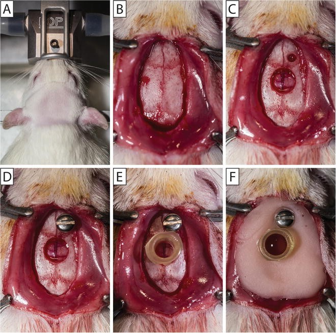
Cranial surgery for hub placement in the rat. The rat’s head is shaved and the animal is secured in a stereotaxic frame with a continuous flow of isoflurane via a nose cone (a). A midline incision is made to expose the skull and the overlying fascia is removed (b). A Dremel tool is used to make two pilot holes. The screw hole is expanded with a finger nail drill and 5/64″ drill bit (c). A 4.7 mm diameter trephine is used to create a cranial disc that is removed to expose the underlying dura (c). A stainless steel screw is secured into the screw hole (d). Small drops of cyanoacrylate gel are placed on the outside of the constructed injury hub, and the hub placed inside the craniectomy (e). After the cyanoacrylate gel dries, the injury hub and screw are covered in methyl methacrylate cement and the injury hub is filled with saline (f)
-
3.
Secure animal in a stereotaxic frame equipped with a nose cone for continuous inhalation of isoflurane (2.0–2.5 %) (Fig. 3a). The back of the front incisors should be flush with the bite bar, without tension applied to the teeth. If you observe mouth breathing, check the positioning of the teeth over the bite bar and/or reposition the nose cone to allow for normal respiration.
-
4.
Apply ophthalmic ointment to the eyes to keep them moist during the surgery.
-
5.
Prepare the surgical area with 70 % alcohol and betadine solution (antiseptic).
-
6.
Monitor anesthesia by observing muscle relaxation, in addition to assessing the toe pinch reflex. Animals under appropriate anesthesia will have a steady respiration rate.

3.4 Cranial Surgery for Hub Placement
-
1.
Make a midline sagittal incision extending from between the eyes, to the base of the skull, just past the ears. To avoid excessive bleeding, avoid cutting the muscle at the base of the skull (Figs. 3b and 4a).
Fig. 4 
Cranial surgery for hub placement in the mouse. A midline incision is made to expose the skull and the overlying fascia is removed (a). Vetbond tissue adhesive is used to secure a disc shaved from weed whacker line at the location of the craniectomy (b). A 3 mm diameter trephine is used to create a cranial disc that removed to expose the underlying dura (c). Small drops of cyanoacrylate gel are placed on the outside of the constructed injury hub, and the hub placed outside the craniectomy (d). After the cyanoacrylate gel dries, the injury is covered in methyl methacrylate cement (e) and the injury hub is filled with saline (f)
-
2.
Expose the skull and scrape the fascia from the skull using a delicate bone scraper, cotton swabs, and gauze. Clear away temporal muscle as necessary. If greater exposure is needed, stretch the skin by applying pressure with the fingers (Figs. 3b and 4a).
-
3.
Attach Bull Dog clips to the edges of the incision (two anterior, two posterior) to expose the surgical site. When the Bull Dog clips fall down, the weight will hold the incision open.

3.5 Cranial Surgery for Hub Placement-Rat
-
1.
Mark the locations on the skull of the screw hole (1 mm lateral to bregma and 1 mm rostral to the coronal suture on the right side) and craniectomy center (midway between bregma and lambda, over sagittal suture). The skull screw is used to secure the injury hub in place.
-
2.
Drill pilot holes at both markings using the Dremel tool and burr bit.
-
3.
Expand the screw hole with a finger nail drill and 5/64″ drill bit (Fig. 3c).
-
4.
Place the centering pin inside the 4.7 mm diameter trephine. Anchor the centering pin in the pilot hole at the craniectomy center.
-
5.
Continually turn and spin the trephine to make a craniectomy without disrupting the underlying dura. Keep trephine clean by using a toothbrush to remove bone debris from the trephine teeth. Apply saline to moisten the bone and aid in trephination . As needed, angle the trephine to evenly cut around the craniectomy .
-
6.
Frequently check the progress of the craniectomy by applying mild pressure to the center of the craniectomy. As the skull thins, the craniectomy will be able to move independently of the skull. The craniectomy is complete when the bone can move freely in all directions.
-
7.
Remove the bone piece working around the circumference using the Wedelstaedt and scalpel, or two Wedelstaedt instruments without disrupting the dura. When the bone has been removed, gently clear any blood from the craniectomy site (Fig. 3c). If the surgery site continues to bleed when skull is removed (see Note 3 ).
-
8.
Secure a stainless steel screw in the skull screw hole. Hold the screw with forceps and advance the screw with a screwdriver (Fig. 3d).
3.6 Cranial Surgery for Hub Placement— Mouse
-
1.
Shave weed whacker line with a razor blade as thin as possible to make a circular disc that is an equal thickness on all sides. Disc should be level when placed on the skull.
-
2.
Pick up the disc with side-grasping forceps. Dip the cranial disc into a drop of Vetbond tissue adhesive placed on a nonabsorbent surface.
-
3.
Place the disc at the location of the craniectomy (midway between bregma and lamda on the sagittal suture). To drop the disc, release the forceps and use a wooden applicator stick to properly position the disc. Once in position, use a Kimwipe tissue to wick away any excess Vetbond (Fig. 4a, b). Allow the Vetbond to fully dry before beginning to trephine.
-
4.
Place the 3.0 mm trephine over the disc and perform the craniectomy by continually turning and spinning the trephine without disrupting the underlying dura. Keep trephine clean by using a toothbrush to remove bone debris from the trephine. Apply saline to moisten the bone and aid in trephination. As needed, angle the trephine to evenly cut around the craniectomy. If the disc comes off while trephining (see Note 4 ).
-
5.
Frequently check the progress of the craniectomy by applying mild pressure to the center of the craniectomy. As the skull thins, the craniectomy will be able to move independently of the skull. The craniectomy is complete when the bone can move freely in all directions.
-
(a)
Under magnification, remove the bone piece working around the circumference using the Wedelstaedt and scalpel, or two Wedelstaedt instruments without disrupting the dura (Fig. 4c). When the bone has been removed, gently clear any blood from the craniectomy site.
-
(a)
3.7 Injury Hub
3.7.1 Injury Hub Construction
-
1.
Attach a 22-gauge, 1½″ needle to a 1 cm3 syringe. Place the needle into a laboratory bench pad (Fig. 2a).
-
2.
Cut the female Luer-Loc hub from the needle using a razor blade (Fig. 2a). The cut is made parallel to the Luer-loc with an outer diameter of ~4.7 mm for the rat, and ~3.0 mm for the mouse. See Note 5 for tips.
-
3.
Inspect the cut edge of the injury hub and trim to size and level as necessary.
-
4.
For the rat, bevel the cut edge of the injury hub with a cosmetic pencil sharpener (Fig. 2b).
-
5.
Shave thin burrs around the injury hub starting at the Luer-Loc edge in the direction of the cut edge using a razor blade (Fig. 2c).
3.7.2 Injury Hub Placement
-
1.
Hold the hub in tissue forceps (behind the teeth). Apply small drops of cyanoacrylate gel on the outside of the hub, just above the cut end.
-
2.
Position the hub over the craniectomy (using magnification for the mouse). For the rat, the injury hub fits inside the craniectomy (Fig. 3e). For the mouse, the injury hub fits outside the craniectomy (Fig. 4d).
-
3.
Using a wooden applicator stick (cut a sharp angle) gently scrape the cyanoacrylate gel down the injury hub onto the skull. Apply more cyanoacrylate gel if needed to the junction between the injury hub and the skull to firmly adhere the injury hub to the skull in addition to creating a seal.
-
4.
After the cyanoacrylate gel dries, cover the injury hub (and screw) in methyl methacrylate cement (Figs. 3f and 4e). Apply the methyl methacrylate cement from a 1 cm3 syringe when it is thick enough to hold shape.
-
5.
When the methacrylate cement has dried, fill the injury hub with saline (Figs. 3f and 4f).
-
6.
Place a suture at both the anterior and posterior edges of the incision.
-
7.
Remove the animal from the stereotaxic frame and anesthesia. Place the animal in a recovery cage on a heating pad until the animal is awake and alert. Monitor animals for outward signs of pain or distress.
3.8 Injury
Before using the injury device, check that when the weighted pendulum arm is hanging in a neutral position (at 0°) that it is flush and centered on the foam pad at the end of the plunger. Adjust as needed. Drop the pendulum hammer several times to prime the device. Remove any air bubbles (see Notes 6 – 8 ).
-
1.
Reanesthetize the animal after an approximately 60-min recovery period from surgery.
-
2.
Visually inspect inside the injury hub for debris, blood or dried dental acrylic. Clean out the injury hub using a small cotton tip applicator or irrigate with saline if necessary, see Note 9 .
-
3.
Fill the injury hub with sterile saline until a bead of fluid is formed by surface tension (Figs. 5a and 6a). Remove any air bubbles from inside the hub.
Fig. 5 
Midline fluid percussion injury in the rat. The injury hub is filled with sterile saline until a bead of fluid is formed (a). The plunger is pressed to produce a drop of water at the end of the injury device. Creating continuity between the fluid of the cylinder and the fluid in the injury hub, the female Luer-Loc of the injury hub is connected to the male Luer-Loc fitting on the injury device by laying the rat on their right side and holding it with your left hand (b). Following a toe pinch response, the pendulum is released to injure the animal. The animal is placed in a supine position on a heating pad until the animal spontaneously rights itself (c). The condition/appearance of the surgical site and brain tissue beneath the injury site is observed and recorded (d)
Fig. 6 
Midline fluid percussion injury in the mouse. The injury hub is filled with sterile saline until a bead of water is formed (a). Creating continuity between the fluid of the Luer-Loc extension tube and the fluid in the injury hub, the female Luer-Loc of the injury hub is connected to the male Luer-Loc fitting on extension tube which is connected to injury device (b). Following a toe pinch response, the pendulum is released to injure the animal while it is lying on its side (c). Immediately after injury the animal is placed on its side until the animal spontaneously rights itself (c). The condition/appearance of the surgical site and brain tissue beneath the injury site is observed and recorded (d)
-
4.
To avoid air between the hub and device, press the plunger so that a drop of fluid is produced at the end of the injury device. Connect the female Luer-Loc injury hub on the animal to the male Luer-Loc fitting on the injury device (Figs. 5b and 6b). Create continuity between the fluid of the cylinder and the fluid in the injury hub. For handling and placement during injury, see Note 10 .
-
5.
Check the animal for a toe pinch response. Once a normal breathing pattern returns (1–2 breaths per second) and the animal has a positive toe pinch response, release the pendulum to injure the animal. Secure the pendulum after it strikes the plunger and return it to the catch.
-
6.
Immediately after the injury, start a timer to measure the duration of the suppression of the righting reflex .
-
7.
Remove the injury hub by pressing on the bridge of the nose for leverage. Visually inspect the hub for obstructions.
-
8.
Observe and record the duration and extent of apnea or seizure. Note the condition/appearance of the surgical site and brain tissue beneath the injury site and record brain herniation and hemorrhage. If the dura is breached, the animal should be euthanized and not included in the study, see Note 11 for details.
-
9.
Control bleeding if necessary. Leave the craniectomy open. Close the wound (i.e., suture or staple) and apply topical lidocaine and antibiotic ointment.
-
10.
Place the animal in a supine position on a heating pad (Fig. 5c). The time elapsed until the animal spontaneously rights is recorded as the righting reflex time.
-
11.
Once the animal has righted, place it in a designated recovery area equipped with a heating pad.
-
12.
When the animal regains normal ambulatory behavior , it can be returned to its home cage.


3.9 Postoperative Care
3.9.1 Postoperative Evaluations
-
1.
Following injury, animals should be visually monitored for continued recovery every 10 min post-injury (for the first hour). Within 15–20 min after injury, surviving animals should be alert. Within 1 h after injury, animals should be ambulatory. Brain-injured and uninjured control animals typically show no outward effects once they have recovered from anesthesia, and resume normal eating, drinking, and grooming patterns. Typically animals return to sleep, as the injury occurs during their sleep cycle.
-
2.
Postoperative evaluations should be done daily (for a minimum of 3 days). Follow the postoperative evaluation sheet to record the external examination, physical examination, suture site, and a pain evaluation. Typically, animals require no special supportive care after surgery. This injury does not produce overt signs of postoperative pain, and do not call for pain monitoring or drugs to manage pain. Caution should be taken in administering such compounds, as they can influence outcome (for review see [7]).
3.9.2 Postoperative Weight
-
1.
Weigh animals daily. Record weights on the evaluation sheet.
-
2.
Animals can lose up to 20 % of their body weight after surgery and injury. It is beneficial to prophylactically provide mash (chow + water) and/or place normal rat chow on the floor of the cage to facilitate weight gain.
-
3.
If by the second day post-injury, there is continued weight loss, the animals will likely require fluid injections (0.9 % sterile saline) to prevent dehydration. Consult a local veterinarian for advice.
-
4.
Weight loss exceeding 20 % of their body weight indicates significant injuries that require intensive postoperative care or euthanasia.
4 Advantages, Limitations, Complications
4.1 Advantages
-
1.
Midline fluid percussion injury (mFPI) is scalable to induce a highly reproducible brain injury that models the clinical sequelae of concussion . Using this model, brain injury is induced by a 20 ms fluid pulse delivered onto the intact dura through a craniectomy [8], defining this technique as a model of traumatic brain injury rather than a head injury. While this model necessitates breaching the cranial vault, the skull is sealed to the injury device, recreating a closed system, which approximates a closed head injury with a decompressive craniectomy . This model allows for the injury to be induced after a recovery from anesthesia which returns the animals to a condition that resembles the human condition, thus enhancing the face validity. The bilateral diffuse pathology in the absence of a cavitation also resembles the human condition of concussion, in which cavitation is rare.
4.2 Limitations
-
1.
In contrast to the tissue destruction caused by other brain injury models, mFPI results in tissue disruption. There is variability in the extent of damaged tissue and range of physiological responses among animals because tissue disruption, unlike tissue destruction, does not have a ceiling effect. The injury to brain occurs within a range which necessitates large group sizes to detect significant effects.
5 Notes
-
1.
The plunger impact pad on the fluid cylinder should be replaced every 8–12 months. Information and instructions for the setup, cleaning, and maintenance of the FPI device can be found in the FPI Operation Manual: http://www.radiology.vcu.edu/docs/FPIOperationManual.pdf.
-
2.
When using an inhaled anesthetic, it is recommended that all procedures are performed in a well-ventilated area, on a downdraft or similar table, or in a type II biosafety cabinet to minimize anesthesia exposure to the surgeon (current OSHA recommendation for halogenated gasses is <2 ppm).
-
3.
If the surgery site continues to bleed when the skull is removed, lightly remove blood with gauze. Adding saline can create hydrostatic pressure that will reduce bleeding. If the site continues to bleed, control the bleeding with Gelfoam. Excessive wiping or dabbing at the craniectomy site will prevent blood clotting and worsen the bleed.
-
4.
If the disc comes off while trephining during a mouse surgery, clean excess dried glue from the area and apply a new disc using Vetbond. However, if the bone can move independently of the skull in an area, use a small dot of superglue to attach a new disc. Vetbond will run and may touch the surface of the dura compromising the surgery.
-
5.
When constructing the injury hub for mice, to confirm the proper diameter you can place the trephine through the hub and confirm a tight fit.
-
6.
Air bubbles in the FPI device can prevent an accurate measurement of the injury magnitude. When air is present in the device, the oscilloscope reading will have many jagged peaks instead of a smooth curve with one peak. The syringe ports can be used to remove any air that enters the device. One way for air to become trapped in the fluid cylinder is after cleaning of the cylinder. This can be minimized by rinsing with a spot remover solution for the dishwasher (e.g., Jet Dry).
-
7.
Air bubbles can also enter the device during the impact. To prevent air bubbles it is necessary to use two 10 mL syringes during preparation of the device between rat injuries. After injury, remove the rat from the male Luer-loc fitting on the end of the device (Fig. 1). Next, a 10 mL syringe with a female Luer-loc fitting should be attached to the device. Pull up on the syringe to remove fluid contaminated with blood or air from the device. Lastly, a second 10 mL syringe containing clean deionized water should be attached to the device. Pull up on the syringe to remove any air bubbles from the device. Check that when the weighted pendulum arm is hanging in a neutral position (at 0°) that it is flush and centered on the foam pad at the end of the plunger. Adjust as needed. Drop the pendulum hammer several times to prime the device. Between every rat injury a syringe should be attached and “dirty” water removed, then a second “clean” syringe should be attached to prime the device.
-
8.
It is important to make sure that the Luer-loc extension tubing is free of air bubbles before each mouse injury. Hold the end of the tubing higher than the connection point on the device. Lightly tapping the extension tubing will force air bubbles to the end of the tubing where they can easily be removed. Between each mouse injury, remove all air bubbles from the tubing. Check that when the weighted pendulum arm is hanging in a neutral position (at 0°) that it is flush and centered on the foam pad at the end of the plunger. Adjust as needed. Drop the pendulum hammer several times to prime the device.
-
9.
When placing the injury hub over the craniectomy , cyanoacrylate gel can spread on to the dura. If the cyanoacrylate is not thoroughly dry forming a seal, the methyl methacrylate can also spread under the injury hub and onto the dura. These substances on the dura will change mechanical properties and alter the injury. Visual inspection is necessary to identify cyanoacrylate gel or methyl methacrylate on the dura, as well as any other obstruction over the injury site, such as a blood clot.
-
10.
For the injury, rats should be held in your left hand lying on their right side. Attach the rat directly to the device (Fig. 5b). For mice, attach them to the device using a Luer-Loc extension tube (Fig. 6b).
-
11.
During the cranial surgery, the dura can be compromised by the trephination or removal of the bone. When the injury is induced, pressure from the fluid pulse will cause the dura to tear and the brain will herniate through the craniectomy . If the dura is compromised, the injury becomes inconsistent and should be classified as a technical failure. A dura breach will extend the opening of the blood–brain barrier and displace neural tissue. Animals with a dura breach should be excluded from any study.
References
Dixon CE, Lighthall JW, Anderson TE (1988) Physiologic, histopathologic, and cineradiographic characterization of a new fluid-percussion model of experimental brain injury in the rat. J Neurotrauma 5:91–104
Thibault LE, Meaney DF, Anderson BJ, Marmarou A (1992) Biomechanical aspects of a fluid percussion model of brain injury. J Neurotrauma 9:311–322
Dixon CE, Lyeth BG, Povlishock JT, Findling RL, Hamm RJ, Marmarou A, Young HF, Hayes RL (1987) A fluid percussion model of experimental brain injury in the rat. J Neurosurg 67:110–119
McIntosh TK, Noble L, Andrews B, Faden AI (1987) Traumatic brain injury in the rat: characterization of a midline fluid-percussion model. Cent Nerv Syst Trauma 4:119–134
McIntosh TK, Vink R, Noble L, Yamakami I, Fernyak S, Soares H, Faden AL (1989) Traumatic brain injury in the rat: characterization of a lateral fluid-percussion model. Neuroscience 28:233–244
Carbonell WS, Maris DO, McCall T, Grady MS (1998) Adaptation of the fluid percussion injury model to the mouse. J Neurotrauma 15:217–229
Rowe RK, Harrison JL, Thomas TC, Pauly JR, Adelson PD, and Lifshitz J (2013) Using anesthetics and analgeics in experimental traumatic brain injury. Lab Anim (NY) 42:286–291 doi:10.2038/laban.257
Lifshitz J (2008) Fluid percussion injury. In: Chen J, Xu X-M, Xu Z, Zhang CJ (eds) Animal models of acute neurological injuries. The Humana Press Inc., Totowa, NJ
Author information
Authors and Affiliations
Corresponding author
Editor information
Editors and Affiliations
6 Appendix: Fluid Percussion Brain Injury
6 Appendix: Fluid Percussion Brain Injury


Rights and permissions
Copyright information
© 2016 Springer Science+Business Media New York
About this protocol
Cite this protocol
Rowe, R.K., Griffiths, D.R., Lifshitz, J. (2016). Midline (Central) Fluid Percussion Model of Traumatic Brain Injury. In: Kobeissy, F., Dixon, C., Hayes, R., Mondello, S. (eds) Injury Models of the Central Nervous System. Methods in Molecular Biology, vol 1462. Humana Press, New York, NY. https://doi.org/10.1007/978-1-4939-3816-2_13
Download citation
DOI: https://doi.org/10.1007/978-1-4939-3816-2_13
Published:
Publisher Name: Humana Press, New York, NY
Print ISBN: 978-1-4939-3814-8
Online ISBN: 978-1-4939-3816-2
eBook Packages: Springer Protocols