
Abstract
The “PIR”-based infrared sensor security system is unveiled. With the help of this sensor, we can conserve energy and manage resources efficiently while using less memory space. When an intruder or human passes through the system or place where the PIR sensor is installed, it is responsible for detecting the change in infrared radiation levels. Voltages alter in response to changes in radiation levels, which subsequently amplifies the signal and results in the production of sound. As a result, it is beneficial in many contexts and applications. When compared to the current system, this type of technology has several advantages.
Access provided by Autonomous University of Puebla. Download conference paper PDF
Keywords
1 Introduction
Any person must have the need for security. For a calm life, it is essential that we feel secure and everything is okay. But how can one achieve that sense of security in this dangerous world where crime, terror, and terrorism are at their highest? We have a solution in the form of security systems using PIR sensor, and more and more people are installing them as a result to feel protected and secure (Salunke et al. 2021). For security and safety reasons, a variety of electronic security systems can be utilized at home and other crucial workplaces.
Our paper mainly depends on a scenario, and the model is constructed based on that. This security system model is designed in scenarios where expensive diamonds are kept for the showcase in a palace. Whenever a person or any object is around the expensive product within the measured circles, the security team will be notified, and the action would be taken on priority.
A security alarm is a tool used for safety (Takkar et al. 2021). It has numerous applications in the security and defense sectors, ranging from the protection of low-value organizational assets to the security of basic household goods. They were formerly pricey answers to security issues. This type of security system is becoming more accessible due to cost-cutting measures and rapid technical improvements.
A transmitter and a receiver are typically used in an electronic security system. In this case, the receiver receives an IR that was sent or transmitted by the transmitter. The device's IR beam is turned off when a person walks or passes across it, setting off the alarm. However, there are drawbacks to this kind of device, including poor line of sight and a small signal range. Using a PIR sensor, we can get rid of these drawbacks. A wireless security system called a PIR sensor-based security system places pyroelectric infrared motion sensors on each of the four sides of the area to be monitored, i.e., the front, back, left, and right.
2 Literature Review
A simple alarm unit and manually switch dependent sensors were suggested by Harshal Hemane and Debarati Sen. When a human moves in front of the motion sensor on a laser security system, the system's alert is set off by the person's body heat. In their research paper, “LASER BASED SECURITY SYSTEM FOR HOME,” the alarm also alerts the security monitoring business and the local law enforcement (Hemane et al. 2022).
According to M. N. Lafta et al., design and fabrication of alarming system based on laser and LDR, the laser and LDR systems have a broad operating range and are highly sensitive. The laser's light is detected by an LDR that is connected to the circuit. Any time the Light's beam is altered, a warning is raised. This extremely reactive, low-computing-requirement approach is ideal for industrial applications, intelligent surroundings, and monitoring (Lafta et al. 2022).
The cloud-based intruder security system that Francis et al., proposed when compared to other security systems, the cloud-based intruder security system is more effective and safer. It can also be accessed and remotely viewed from any location, making it easy to guard. Despite the rapid advancement of intruder detection and security technologies, there are still certain problems with installation and maintenance expenses that need to be fixed (Lafta et al. 2022).
The purpose of the review is to raise awareness of the security alarm's use of Internet of Things (IoT) technology and the security measures that one should take on a regular basis due to the rise in burglaries and kidnappings in society today. It also aims to highlight the difficulties that arise when a security system is connected to the internet and how to prevent all cyber-criminal attacks.
3 Working Process
Security is the primary ideology. This is based on a PIR sensor that has an IC that emits buzzer or siren noises. The PIR sensor detects the infrared radiation that people release, and it subsequently generates a digital output. It is primarily utilized in applications for automatic lighting, security alarms, and motion detectors (Francis et al. 2022). They typically detect movement by detecting changes in infrared radiation. The Arduino Uno receives this digital output in return.
When a human or any kind of object is found, it thus makes the sound. A buzzer is activated.
It is used to produce sounds like police, fire engine, ambulance, and machine gun sirens, among others.
After the detection, the expensive ornament has been pulled down to a security place through a 12 V motor.
The System Works in the Following Steps
-
The system developed is kept running always.
-
The detector is connected to the sensing circuit.
-
When the beam is interrupted and cannot reach the detector, its voltage output changes, and the circuit sense the change and put out a warning signal.
-
Once the warning signal is on. The admin is notified with the message.
4 Working Principle
PIR sensors can often detect animal or human movement within a specified range. PIR is constructed of a pyroelectric sensor, which can recognize various infrared radiation intensities. The detector passively absorbs energy rather than emitting any of its own.
It picks up environmental infrared radiation. The pyroelectric gadget (Budijono et al. 2014) produces an abrupt electrical signal when focused on the optical system once infrared radiation from the human body particles with temperature is present.
Simply said, a human body or any other animal that passes by blocks the PIR sensor’s first slot. The two bisects have a positive differential change as a result. The sensor creates a negative differential shift between the two bisects when a human being departs the sensing area (Fig. 1).

Representation of human being interference in sensing area
5 Circuit Components
-
A.
NodeMCU.
-
B.
PIR sensor.
-
C.
12 V motor.
-
D.
Buzzer.
-
E.
Connecting wires.
-
F.
Breadboard.
-
G.
USB cables A–B.
-
H.
Relay module.
-
I.
12 V power supply.
-
A.
Node MCU: A low-cost System-on-a-Chip (SoC) called the ESP8266 serves as the foundation of the open-source Node Microcontroller Unit (NodeMCU). The Espressif Systems-designed and -produced ESP8266 has all of the essential components of a computer, including CPU, RAM, networking (WiFi), and even a contemporary operating system and SDK. This makes it a fantastic option for all types of Internet of Things (IoT) projects (Fig. 2).
Fig. 2 
NodeMCU
-
B.
PIR Sensor: An electronic sensor that measures the infrared (IR) light emitted by objects in its field of vision is known as a passive infrared sensor (PIR sensor). Most frequently, they are utilized in PIR-based motion detectors (Soltani et al. 2022). PIR sensors are frequently utilized in autonomous lighting and security alarm systems. PIR sensors can detect movement in general but cannot identify who or what moved (Fig. 3).
Fig. 3 
PIR sensor
-
C.
12 V Motor: A straightforward rotation motor spins 360° while running at 6000 RPM (Fig. 4).
Fig. 4 
12 V motor
-
D.
Buzzer: A beeper or buzzer, for example, could be electromechanical, piezoelectric, or mechanical in design. The major function of this is to convert the signal from audio to sound (Andriansyah et al. 2017). It is often powered by DC voltage and used in timers, alarm clocks, printers, computers, and other electronic devices. It can produce a variety of sounds, including alarm, music, bell, and siren, according on the varied designs (Fig. 5).
Fig. 5 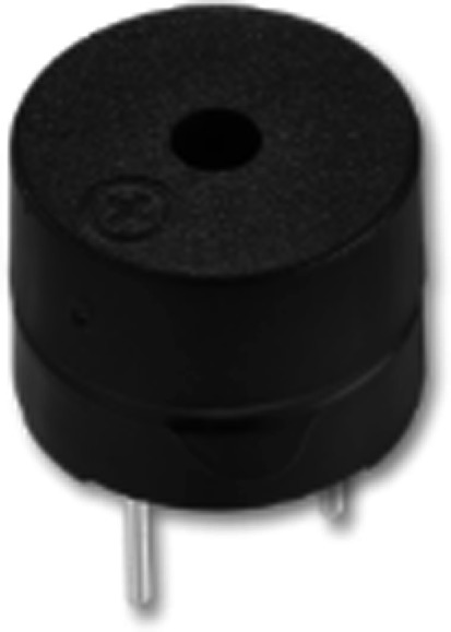
Buzzer
-
E.
Relay Module: An electrical switch that is activated by an electromagnet is a power relay module. A distinct low-power pulse from a microcontroller is used to trigger the electromagnet (Satheeshkumar et al. 2017). The electromagnet pulls when it is turned on, allowing a circuit to be opened or closed (Fig. 6).
Fig. 6 
Relay module
-
F.
12VDC 2A: A 12 V power supply that you can connect into a standard outlet and works with inputs of 100–240 VAC. The most dependable and likely to function for all of the components you select (Saranraj et al. 2020). Use it when your circuit doesn't need to be mobile or situated somewhere without wall power (Fig. 7).
Fig. 7 
12VDC 2A


6 Circuit Diagram
How each component is connected to each other to achieve the project “Security System.”
-
A.
For 12 V power supply, negative terminal is connected to DC 12 V motor negative terminal.
-
B.
For 12 V power supply, positive terminal is connected to relay model (COM) terminal.
-
C.
Relay model (NC) terminal is connected to DC 12 V motor positive terminal.
-
D.
Positive terminal of PIR sensor is connected to 3.3 V of NodeMCU.
-
E.
Negative terminal of PIR sensor is connected to GND of NodeMCU.
-
F.
Output terminal of PIR sensor is connected to D1 pin of NodeMCU.
-
G.
Negative terminal of buzzer is connected to GND pin of NodeMCU.
-
H.
Positive terminal of buzzer is connected to D2 pin of NodeMCU.
We have programmed NodeMCU using Arduino IDE. Figure 9 shows the code that was used to upload into NodeMCU. Figure 10 shows how Admin/Security being notified when motion is detected (Fig. 8).

Circuit diagram of the proposed model of security system

Code to upload NodeMCU
7 Project Image


Notification detected during motion
8 Conclusion
Author created the security on such a low budget. It had received complete security protection. High-tech home security options like laser security systems were previously exclusively accessible to the wealthy. It is a simple alarm system with manually switch dependent sensors. When a human moves in front of the sensor on a security system, that person cuts the laser, setting off the alarm.
References
Andriansyah M, Subali M, Purwanto I, Irianto SA, Pramono RA (2017) e-KTP as the basis of home security system using Arduino Uno. In: 2017 4th international conference on computer applications and information processing technology (CAIPT), pp 1–5. https://doi.org/10.1109/CAIPT.2017.8320693
Budijono S, Andrianto J, Noor MAN (2014) Design and implementation of modular home security system with short messaging system. EPJ Web Conf 68:00025. https://doi.org/10.1051/epjconf/20146800025
Dehghani Soltani M et al (2022) Safety analysis for laser-based optical wireless communications: a tutorial. Proc IEEE 110(8):1045–1072. https://doi.org/10.1109/JPROC.2022.3181968
Francis A, Thanga S, Thiruneelakandan T (2022) Cloud based intruder security system. https://doi.org/10.5281/zenodo.5839759
Hemane H, Sen D (2022) Laser based security system for home. 2395-0056
Lafta MN et al (2022) Design and fabrication of alarming system based on laser and LDR. In: 2022 5th international conference on engineering technology and its applications (IICETA), pp 550–553. https://doi.org/10.1109/IICETA54559.2022.9888487
Salunke A et al (2021) Laser tripwire security system using Arduino Uno. Int J Eng Res Appl (IJERA) 11(6):56–59
Saranraj B, Dharshini NSP, Suvetha R, Bharathi KU (2020) ATM security system using Arduino. In: 2020 6th international conference on advanced computing and communication systems (ICACCS), pp 940–944. https://doi.org/10.1109/ICACCS48705.2020.9074429
Satheeshkumar K, Ajithkumar N, Gopinath PA, Ranjithkumar S, Chandramohan J (2017) Implementation of smart home automation and security system using Arduino and Wi-Fi through android application. Int J Eng Res Technol (IJERT) ICONNECT 5(13)
Takkar S et al (2021) Advanced ATM security system using Arduino Uno. In: 2021 9th international conference on reliability, Infocom technologies and optimization (trends and future directions) (ICRITO), pp 1–5. https://doi.org/10.1109/ICRITO51393.2021.9596341
Author information
Authors and Affiliations
Corresponding author
Editor information
Editors and Affiliations
Rights and permissions
Copyright information
© 2024 The Author(s), under exclusive license to Springer Nature Singapore Pte Ltd.
About this paper

Cite this paper
Ashwitha, K., Puneeth, B.R., Sumithra, B., Taiyab, M. (2024). Security System Using PIR Sensor. In: Shetty, N.R., Prasad, N.H., Nagaraj, H.C. (eds) Advances in Communication and Applications . ERCICA 2023. Lecture Notes in Electrical Engineering, vol 1105. Springer, Singapore. https://doi.org/10.1007/978-981-99-7633-1_8
Download citation
DOI: https://doi.org/10.1007/978-981-99-7633-1_8
Published:
Publisher Name: Springer, Singapore
Print ISBN: 978-981-99-7632-4
Online ISBN: 978-981-99-7633-1
eBook Packages: EngineeringEngineering (R0)