
Abstract
This chapter introduces the core concepts that underlie computers, unraveling their fundamental attributes and inner working mechanisms. The exploration of what a computer is highlights its essential attribute as a versatile and programmable machine capable of performing various tasks. The difference and interplay between digital and analog values unveil how computers use discrete binary values to represent and process information. From program to programming, hardware to software, composition to working mechanisms, this chapter provides learners with a comprehensive overview of the pivotal concepts that underpin the digital age. Learners will know how computer memory, processing units, and input/output units work together, and how logic gates, the elemental building blocks of digital circuits, are arranged to achieve complex operations. With a deep understanding of binary values, program, hardware, software, information representation, and logic foundations, learners will be empowered to navigate the world of computing with newfound clarity and appreciation.
Access provided by Autonomous University of Puebla. Download chapter PDF
1.1 What is a Computer
In the seventeenth century, the term “computer” described a man whose job was calculation, whereas the term “computress” was used to refer to a woman in the same role. Over time, “computer” also evolved to denote a device designed for performing calculations.
Computers can be classified into two categories based on how they process information: analog computers and digital computers. Analog computers process information using continuous analog quantities, whereas digital computers process information using discrete digits. Further details will be provided in the following.
There are two types of signals: analog signal and digital signal. Analog signals represent continuous quantities. For example, temperature and voltage are considered analog signals because they are continuous quantities. Analog displays represent these continuous values such as by using the position of a needle (Fig. 1.1).

An example of analog display
In contrast, digital signals represent discrete values. A digital display conveys information such as temperature and voltage using numerical representations. The display is limited to showing values within the range of its available digits. For example, in Fig. 1.2, the display reads “12,345.6”. In this context, “discrete values” means that values between 12,345.5 and 12,345.6 cannot be displayed. Additionally, “within the range of its available digits” means that values with more than two decimal places, such as “12,345.67”, cannot be displayed.

An example of digital display
In mathematics, real numbers are analog quantities because they represent continuous values without interruption. In contrast, integers are digital quantities because they are discrete values such as 0, 1, and 2.
Computers can also be classified as either mechanical or electronic, depending on the components used in their construction. Early analog computers are built using mechanical components like gears and levers, making them mechanical computers. In contrast, modern digital computers are built using electronic components, such as transistors and integrated circuits, making them electronic computers. Today the overwhelming majority of computers are electronic digital computers, so the term “computer” hereinafter refers to electronic digital computers.
1.2 Program and Programming
A program (also called code) is a human-written modifiable calculation procedure. It consists of multiple “instructions”, often guiding the execution of elementary operations such as “retrieve data from storage” and “add these numbers”. For example, Fig. 1.3 is a Java program that outputs the sum of two integers a and b, being 5 and 3, respectively.

An example of a Java program
The main body of a program is typically written in English, using alphabets, numbers, and symbols including commas and line breaks. This practice can be attributed to historical factors, such as the initial limitation to English of early computers, the prevalent use of English within the field of computer science, and the necessity for a standardized and universally comprehensible language to facilitate global code collaboration and sharing.
Writing a program is called programming. The formal language for writing programs is called a programming language. There are many programming languages such as Python, Java, C++, and JavaScript. These popular and widely used programming languages all employ English-based syntax and keywords, and this is one of the reasons why English is prevalent in programming.
1.3 Distinguishing Characteristic of a Computer
The key difference between a “computer” and a “calculator” is that a computer can automatically execute calculations based on a program, whereas a calculator requires manual operation. Hence, a computer is a programmable electronic digital computing device.
A computer can perform various calculations automatically if the program is changed. In contrast, a basic calculator, like a pocket calculator, relies on human operation. Complex calculations with a calculator demand manual operation for each step.
• Questions
-
1.
Is a smartphone a computer?
Hint: consider whether a smartphone has the same characteristic as that of a computer.
1.4 Composition of a Computer
The basic components of a computer (Fig. 1.4) are.

Composition of a computer
-
the computing and control unit,
-
the storage unit,
-
the input/output (I/O) unit,
and the “buses” that connect these units [1]. The computing and control unit performs calculations and controls the entire computer. The storage unit stores programs that define computational procedures and the data to be processed. The input/output unit obtains information from the outside and presents calculation results.
The computing and control unit is also called the central processing unit (CPU). In modern computers, the CPU is often combined with integrated circuits (ICs), which include many electronic logic gates. An electronic logic gate has an elementary computational function. More details of logic gates will be given in Sect. 1.7.
The storage unit has many blocks for storing programs and data. The location is indicated by a serial number (usually an integer) called address. The minimum size of storage is called a “bit”, which stores only one “0” or “1”. A group of eight bits is called a “byte”. Addresses are often assigned in byte units.
The input unit receives information from a human. There are many input devices such as keyboards, mice, styluses, handwriting panels, microphones, and cameras. The output unit delivers information to a human. Output devices include displays, printers, speakers, and earphones.
1.5 Hardware and Software of a Computer
Originally, the term “hardware” referred to machinery or devices made of physical materials, often including iron components. In contrast, “software” is a term used to distinguish the non-physical aspects of computing. In the context of a computer, “hardware” refers to its physical components (Fig. 1.5a), whereas “software” refers to the computational procedures and programs that enable its functionality (Fig. 1.5b). Hence, in a computer, hardware operates according to software [2].

Examples of hardware and software in a computer
A computer executes a program in the following procedure:
-
1.
Retrieve instructions from the storage unit.
-
2.
Translate the instructions into machine-readable code.
-
3.
Prepare necessary data.
-
4.
Perform calculation.
-
5.
Store or output the calculation results.
-
6.
Repeat the above steps.
1.6 Representation of Information Inside a Computer
A computer processes all information as digital quantities, represented by combinations of “0” and “1” known as bits. A computer system where the high voltage (or large current) state represents “1” and the low voltage (or small current) state represents “0” is called a “positive logic” system. In contrast, a system where the low voltage state represents “1” and the high voltage state represents “0” is called a “negative logic” system [2]. Which type of system to use should be determined according to need.
A number inside a computer is represented by its binary value, consisting of “0” and “1”.
A character is represented by a numerical value corresponding to the character in the character code used. A character code is a correspondence table linking characters and their corresponding numerical values. There are many types of character codes. The American Standard Code for Information Interchange (ASCII) has been in use since the mid-twentieth century. It uses seven bits to represent an uppercase or lowercase English alphabet, an Arabic number (0–9), a symbol, and a control character such as a line break. For example, the number “0” is expressed by binary 0,110,000 (= decimal 48), and the uppercase letter “A” is expressed by binary 1,000,001 (= decimal 65).
A kanji character in languages such as Japanese cannot be represented by only 1 byte (8 bits), so a kanji is represented by two or more bytes. There are several character codes associating Japanese characters with numbers such as JIS, Shift-JIS, and EUC-JP. In recent years, Unicode has gained increasing prominence. It aims to handle all the characters in the world, including emoji that is often used in mobile messages [2].
Audio and images are converted to digital numbers before being processed. Sound is change in air pressure over time. Since air pressure and time are both continuous quantities, sound is an analog quantity. To be processed inside a computer, an analog quantity needs to be converted into digital values first. This conversion is achieved through a process known as sampling, which involves measuring and recording sound values at regular intervals. If the interval T between measurements is extremely short, the recorded discrete values will be very close to the analog signal, as shown in Fig. 1.6. After being converted to digital values, sound can be processed by using various calculations in a computer.

An example of converting an analog signal to a digital signal
An image such as a photograph is converted into a collection of “points” called “pixels” first and then the color of each pixel is converted to a numeric value. For a monochrome image (i.e. a single color image, often in black and white), the color of one pixel is represented by one number. For example, 0 represents pure black, 255 represents pure white, and the degree of black between pure black and pure white is divided into 254 levels and represented by one number between 1 and 254.
For a color image, the color of one pixel is represented by a set of three numbers. In the RGB system (Fig. 1.7), the three numbers represent the respective ratios of the three primary colors of light: red (R), green (G), and blue (B). Figure 1.8 illustrates how the color purple is represented in the RGB system. In systems other than RGB, one number may represent brightness and the other two numbers may represent the color. Motion pictures, or videos, are decomposed into multiple images first and then processed in the same way as processing images.

Three primary colors of light (RGB)

Representing the color purple in the RGB system
1.7 Computing Mechanism of a Computer
The interior of a computer comprises a multitude of arithmetic circuits. In these circuits, there are many electronic logic gates performing specific operations of “0” and “1” [2].
A combinational logic circuit is a kind of circuit whose output is determined by only the current input. The three most basic logic gates in combinational circuits are NOT, AND, and OR. Their definitions are given in Figs. 1.9, 1.10 and 1.11. In the figures, a truth table means a table showing the corresponding input–output values.

Gate symbol and truth table of logic NOT

Gate symbol and truth table of logic AND

Gate symbol and truth table of logic OR
A logic gate performs logic operation, which involves only binary values 0 and 1. Logic NOT has only one input. It outputs the inverse value of the input. If the input is 0, the output will be 1. If the input is 1, the output will be 0.
Logic AND has two inputs. If either of them is 0, the output will be 0. Only when both inputs are 1 will the output be 1. In other words, 0 AND 0 = 0, 0 AND 1 = 0, 1 AND 0 = 0, and 1 AND 1 = 1. These equations are the expressions of the logic AND operation, similar to the expressions of mathematical multiplication: 0 × 0 = 0, 0 × 1 = 0, 1 × 0 = 0, and 1 × 1 = 1. It should be noted that while logic AND and mathematical multiplication share similarities, they are not identical because logic AND operates with only binary values.
Logic OR has two inputs. If either of them is 1, the output will be 1. Only when both inputs are 0 will the output be 0. In other words, 0 OR 0 = 0, 0 OR 1 = 1, 1 OR 0 = 1, and 1 OR 1 = 1. These equations are the expressions of the logic OR operation, similar to the expressions of mathematical addition: 0 + 0 = 0, 0 + 1 = 1, 1 + 0 = 1, and 1 + 1 = 2.
While some logic operations yield the same result as mathematical calculations, it is essential to note that logic operations exclusively deal with binary values and serve fundamentally different purposes from mathematical calculations. Logic operations and mathematical calculations can be considered as two different computing systems.
By combining basic logic gates, a wide array of calculations can be performed. For example, the addition of two bits A and B can be realized by the circuit shown in Fig. 1.12. The sum of A and B is represented by S (Sum). Since S is only one bit, the sum “2” resulting from the addition “1 + 1” cannot be represented because every bit in a computer can only hold a value of either 0 or 1. Therefore, the digit increase C (Carry) is needed. The truth table for inputs A and B and outputs C and S is shown in Fig. 1.12. This circuit is called a “half adder” and is used for the first digit of addition. A full adder, which includes a carry input from the lower digit, can be realized by using two half adders.

Circuit symbols and the truth table of a half adder
In some circuits, past output is used as input to determine the current output. If the output of a circuit depends on its past output, the circuit is called a flip-flop. A flip-flop circuit has the ability to store information. For example, in the RS flip-flop circuit shown in Fig. 1.13, the current output Q is the result of applying OR then NOT to the current input R and the past output \(\overline{Q}\), and the current output \(\overline{Q}\) is the result of applying OR then NOT to the current input S and the past output Q. Such a circuit that depends on the past output is called a sequential circuit.

An RS flip-flop circuit
Complex processing is achieved by combining a large number of combinational logic circuits and sequential circuits. The integrated circuits introduced in Sect. 1.4 are combinations of many such circuits.
Exercises
-
1.
Create the truth table for multiplying two bits.
• Guidance
You may refer to the truth table for adding two bits (Fig. 1.12). In Fig. 1.12, when A is 0 and B is 0, S is 0 because 0 (A) + 0 (B) = 0 (S). When A is 0 and B is 1, S is 1 because 0 (A) + 1 (B) = 1 (S). When A is 1 and B is 0, S is 1 because 1 (A) + 0 (B) = 1 (S). When A is 1 and B is 1, the result is 2 because 1 (A) + 1 (B) = 2 (S). However, S cannot be 2 because there are only 0 and 1 in a computer. In this case, carry C is needed. Hence, in a computer, “10” represents 2.
Similarly, when creating the truth table for multiplying two bits, first create the input, for example, A and B. Then create the output and name it using an alphabet. Since both A and B can be either 0 or 1, the table should have 22 = 4 rows, as shown in Table 1.1. Fill in the values of each cell in the table. If one column of output is enough, there is no need to create two columns.
-
2.
Create the truth table for the circuit shown in Fig. 1.14.
Fig. 1.14 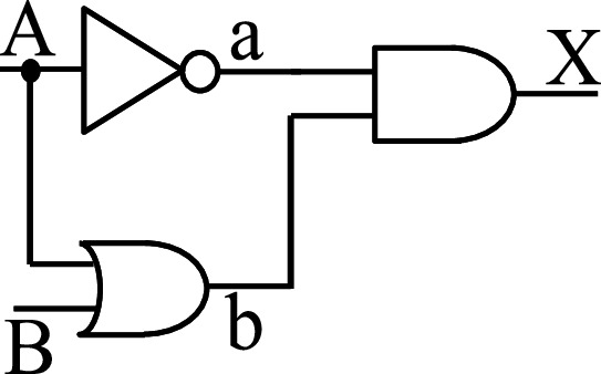
Circuit for exercise problem 2

• Guidance
The following is an example of how to get X:
-
i.
Let “a” be the result of NOT A, as shown in Fig. 1.14
-
ii.
Let “b” be the result of A OR B, as shown in Fig. 1.14
-
iii.
Then X is the result of “a” AND “b”
-
iv.
Both A and B can be either 0 or 1, so the table should have 22 = 4 rows. Calculate X for each of the four input patterns.
Table 1.2 shows the table you should create. Please fill in the values into empty cells. If you find it difficult to get X directly from A and B, you may add two columns, “a” and “b”, as shown in Table 1.3. For each input pattern, you can calculate “a” and “b” first, and then you can get X. For example, when A is 0 and B is 0, a = Not A (Not 0) = 1. b = A OR B (0 OR 0) = 0. As a result, X = a AND b (1 AND 0) = 0. Fill in the next three rows by yourself.
-
*3.
Create the truth table for A AND B AND C.
-
*4.
Create the truth table for NOT (A AND (B OR C)).
-
*5.
Create a circuit for NOT (A AND (B OR C)) by using the gate symbols shown in Figs. 1.9, 1.10 and 1.11.
Problems marked with an asterisk “*” are optional. However, learners are encouraged to work on them independently to enhance their understanding and skills.
References
Brookshear G, Brylow D (2014) Computer science: an overview, 12th edn. Pearson, Reading, MA
Petzold C (2000) Code: the hidden language of computer hardware and software. Microsoft Press, Redmond, WA
Author information
Authors and Affiliations
Corresponding author
Rights and permissions
Copyright information
© 2024 The Author(s), under exclusive license to Springer Nature Singapore Pte Ltd.
About this chapter

Cite this chapter
Weng, W. (2024). Computer. In: A Beginner’s Guide to Informatics and Artificial Intelligence. Springer, Singapore. https://doi.org/10.1007/978-981-97-1477-3_1
Download citation
DOI: https://doi.org/10.1007/978-981-97-1477-3_1
Published:
Publisher Name: Springer, Singapore
Print ISBN: 978-981-97-1476-6
Online ISBN: 978-981-97-1477-3
eBook Packages: Computer ScienceComputer Science (R0)