
Abstract
During the conceptual design phase of civil aircraft systems, it is imperative that engineers accurately establish the functional representation of the system and ensure its correctness to provide a solid foundation for subsequent detailed design. Traditional document-based methods for functional representation frequently result in ambiguity, making it difficult to precisely communicate design requirements. Therefore, the academic community is committed to using model-based system engineering to achieve functional representation. However, existing model-based functional representation techniques primarily focus on describing functional input/output, rather than explicitly expressing functional input/output conversions, which can impede system engineers from verifying functional completeness. In response to this issue, this paper proposes a functional quantitative modeling approach for civil aircraft systems based on SysML. Firstly, a quantitatively-analyzable flow model is established, and a general functional model of integrated structure, state, and behavior is subsequently developed based on this flow model. Next, a hierarchical functional model of the system is introduced. Finally, to verify the proposed approach, the elevator surface control system is employed as an example, and a quantitative analysis of the functional model is presented.
Access provided by Autonomous University of Puebla. Download conference paper PDF
Keywords
1 Introduction
In recent years, complex products have become increasingly complex. Compared with traditional mass-manufactured products, their complexity is reflected in the multi-field coupling and correlation, the complex composition of systems and subsystems, the high degree of coupling, complex functions and functional levels, and complex R&D organizations [1]. During the conceptual design process of civil aircraft systems, engineers need to comprehensively design the aircraft system, clearly describe the relevant functional requirements, and conduct reasonable verification of the system and internal functions, so as to convey clear design intentions and technical requirements to project participants.
Document-based systems engineering has been difficult to meet the requirements of functional accuracy, completeness, and process description, while model-based system engineering (MBSE) is gradually applied to the design of complex product systems, which can identify possible faults and design defects in advance [2]. MBSE can carry out unified modeling management on various design elements in the design process to ensure the consistency between system design data [3]. MBSE can realize the structured expression of functions and provide support for the structured expression of system functions.
According to the study of Chen et al. [4], function refers to the abstraction of the system's effect on its external environment (object) formed in the brain of engineers, so as to expect to change the unsatisfactory external environment (object) to achieve a satisfactory state. Functional representation is the basis of functional modeling, and the representative functional representation methods include: 1) Gerund pair representation, where the verb represents the action performed by the functional object, and the noun represents the functional object; 2) Input-output stream representation, according to the design theory of Pahl et al. [5], the objects of input and output stream can be matter, energy, information and their sub-types; 3) Integrate the representation of verbs and input-output streams, that is, verbs are used to express the purpose of functions, and input-output streams are used to express the interaction between environment and functional object.
With the development of MBSE, there are more and more model-based functional representations, each with its own characteristics. For example, the Function–Behavior–Structure (FBStr) model proposed by Gero et al. [6] focuses on the design process of transition from intent to structure. The Function–Environment–Behavior–Structure (FEBS) model proposed by Deng et al. [7] focuses on the impact of environment on function. The Function–Behavior–State (FBS) model proposed by Umeda et al. [8] focuses on the connection between function and behavior. The Structure–Behavior–Function (SBF) model proposed by Goel et al. [9] focuses on the relationship between system structure and function. The ontology-based product function description model proposed by Guo et al. [10], focusing on functional semantics and reasoning. The State-Behavior-Function (SBF) model proposed by Chen et al. [11] focuses on the relationship between the state change of system structure and the transformation of input and output streams.
Although existing model-based functional representation methods can effectively describe the qualitative aspects of functions, they lack the capability to enable quantified representation and verification of input/output flows in functions. Consequently, they are unable to support the comprehensive representation and verification of system functions.
To address the aforementioned challenges, it is necessary to express the flow and its transformation and conversion involved in the civil aircraft system function, establishes a functional model that can be qualitatively or quantitatively analyzed, which in turn provides the foundation for quantitative analysis and verification of the system function. Specifically, this paper proposes the establishment method of flow models for quantitative analysis based on SysML, in addition to general functional models that integrate structure, state, and behavior based on the established flow model. Moreover, the paper proposes a representation method for the hierarchical functional model. Finally, using the elevator surface control system as an example, this paper illustrates how to establish the general functional models, hierarchical functional model, and how to carry out quantitative model simulation. This example provides a basis for system functional verification.
2 Flow and General Functional Modeling
Existing functional modeling methods often ignore the structural expression of functional flow, and use a noun to represent the input/output flow, which can satisfy the simple representation of functions, but cannot express the relationship between output flow and input flow. For example, it is difficult to determine whether the value of the flow attribute and the type of the flow have changed after the input flows through the functional principal. For this reason, this section provides a modeled representation of the input/output flow, so that the relationship between the input/output flows and the function can be more accurately described.
This section also expresses the function in a structured way. The general functional model refers to a model that integrates structure, state, and behavior without considering the internal composition of the functional object during the modeling process. It can be used to describe the input and output flow, internal state, behavior, etc. In the conceptual design stage of civil aircraft systems, functional modeling is procedural. When a system does not consider internal components, a general functional model of the system can be established; when a function cannot be separated, a general functional model can be established. Based on the flow model, a qualitative/quantitative functional model can be established to provide a basis for quantitative analysis of the general functional model.
2.1 Flow Model Establishment
Flow is the medium through which functional objects interact with the environment, including material flow, energy flow, and information flow. Flow modeling is the process of modeling and expressing flows, that is, to describe flow types and attributes in the form of ‘‘type name + attribute set’’, where ‘‘attribute set’’ is optional. The attributes referred to in this article include physical attributes, chemical attributes, etc., and flow attributes refer to the attributes related to participation in the flow and functional utility (the interaction between the functional object and the environment). For example, electrical energy flow can be used as a flow to participate in some functional utilities. The attributes of electrical energy objects generally include current, voltage, power, frequency, etc. When functional utility involves energy conversion (such as transforming electrical energy into light energy or mechanical energy), the attributes involved in the functional utility may be current, voltage, and power, so current, voltage, and power can be regarded as the flow attributes of electric energy, while frequency is not regarded as its flow attributes.
The basis of functional utility quantitative analysis is that the input/output flow has attributes, and the corresponding attributes have certain constraints. When quantitative analysis is required, the flow must have attributes with definite constraints, but when some constraints are clearly understood in the upstream and downstream of the design, the corresponding constraints do not be displayed. It should be noted that the quantitative analysis does not mean that the results of functional modeling include the principle understanding. The quantitative analysis mentioned here is only related to the attributes of the input/output flow, and has nothing to do with the functional principle understanding. The Block Definition Diagram (BDD) of SysML is a structural diagram that can be used to describe a complex flow model. The block elements in it can describe a single flow model, and are generally identified by a partition box with <<block>>. For example, when performing a qualitative analysis on an electric lamp, the input flow (electricity) may not contain any attributes, as shown in Fig. 1; when performing a quantitative analysis on it, since the electric lamp has a voltage requirement for the electricity flow, the electricity flow model must include the attribute of voltage at this time, and the voltage needs to be defined clear constraints, as shown in Fig. 2.

Electricity flow for qualitative analysis

Electricity flow for quantitative analysis
2.2 The Structure of General Functional Model
The structure of the general functional model consists of internal flows, input/output flow ports, flags, etc. The internal flow is an intermediate flow in the transformation and conversion process of the input and output flow; the input/output flow port is the channel through which the functional object interacts with the environment, that is, the transmission channel of the flow; the flag is an object used to describe the internal state or characteristics of the model. A block in BDD can describe a single model structure: the internal flow and input/output flow ports of a functional model can be described by the component attributes of the block; flags can be expressed by the component attributes or value attributes of the block. The Internal Block Diagram (IBD) of SysML is a structural diagram that can display the specific structure inside the block; the Parameter Diagram (PD) is a specific internal block diagram that can describe the binding connection relationship of related value attributes in the internal composition of the block. Therefore, the internal composition and connection of the general functional model structure can be accurately described by PD or IBD.
Taking the simplified elevator surface power control unit (PCU) as an example, the PCU receives the electrical signal output by the primary actuator control electronics (P-ACE), controls the output of the hydraulic components, and manipulates the position of elevator surface through a sector disk, cable, or connecting rod assembly. The structure of the PCU functional model can be described by using block and IBD, as shown in Fig. 3 and Fig. 4. For example, ‘‘inSOVH’’ and ‘‘inSOVL’’ are the internal flows of the PCU functional model, and the input flow ‘‘SOVH’’ passes through the input port ‘‘pSigSOVH’’, stored by the internal flow of ‘‘inSOVH’’, provides an intermediate medium for flow transformation and conversion.

The structure of PCU functional model

Internal connections of PCU functional model
2.3 The State of General Functional Model
The state of general functional model is an abstraction of a set of specific attribute values, where attributes include physical properties (such as physical connections inside functional object) and chemical properties. Engineers can use the form of ‘‘state name + description’’ to express the general functional model state, where ‘‘description’’ is optional. For example, when an operational amplifier power supply circuit has no effective voltage (that is, state = ‘‘off’’), the function of the operational amplifier cannot work properly. The State Machine Diagram (SMD) of SysML is a kind of behavior diagram, which can be used to describe the state of the model and the transition between states [12]. Model states can be described by state elements in a state machine diagram.
The simplified PCU has two states: “NotEngaged” and “Engaged”; in order to facilitate model expression, engineers can define the auxiliary state “off”, as shown in Fig. 5.

The states and state transitions of PCU functional model
2.4 The Behavior of General Functional Model
The types of interaction between functional objects and the environment mainly include: 1) There is input but no output: environmental input causes the state of the object to change, such as the water storage function of a pool, that is, the water flow input causes the water level of pool to change; 2) There is output but no input: the object directly acts on the environment, such as battery discharge function, that is, battery outputs electric energy to the outside; 3) There is input and output: the environmental input is output to the environment through the internal function of the object. Functional model behavior can be defined as an activity in which a functional object interacts with the environment to change one or both of them. General functional model behavior can be divided into state transition behavior and flow-processing behavior.
-
(1)
State Transition Behavior
There are state switching activities in the multi-state general functional model, and such activities can be called state transition behaviors. The trigger event is the event that causes the model state to change. The trigger event includes input/output flow interaction events, time events, and model attribute change events. The state transition behavior of the model can be represented by SMD: a solid line with an open arrow can be used to mark the transition of the model from the source state to the target state, and the trigger event can be described by the conditions on the solid line.
The state transition behavior of the PCU is shown in Fig. 5. For example, when the ‘‘stateFlag = 1’’ event occurs, the PCU state will switch from ‘‘off’’ to ‘‘Engaged’’.
-
(2)
Flow-Processing Behavior
In a specific model state, the model can complete the corresponding flow transformation or conversion activities, which can be called flow-processing behavior. The ‘‘input flow + output flow’’ binary expression is difficult to express the flow-processing behavior of complex models in different states, that is, it is impossible to determine the type of flow-processing behavior: a) the flow attribute value changes, b) the flow type changes. But based on the flow model and flow-processing behavior, the function can be expressed qualitatively or quantitatively. When the flow attributes and attribute constraints are clear, the flow-processing behavior of the functional model can be quantitatively analyzed. It should be noted that the flow-processing behavior should follow general physical rules, such as the law of energy conservation. For example, in the qualitative analysis of lamp function, the input flow is electrical energy (flow_electricity), the output flow is light energy (flow_opticalEnergy), the flow-processing behavior can be described as: when the input is flow_electricity, flow_electricity transforms to flow_opticalEnergy, and outputs flow_opticalEnergy. In the quantitative analysis of lamp function, the input flow is electrical energy with clear attributes and attribute constraints (flow_electricity: voltage = 220 V, power >= 0 W), and the output flow is light energy with clear attributes and attribute constraints (flow_opticalEnergy: power >= 0 W), the flow-processing behavior can be described as: inputs flow_electricity, flow_electricity is converted into flow_opticalEnergy, and flow_opticalEnergy is output externally, and the power of flow_opticalEnergy is equal to the power of flow_electricity.
Flow-processing behavior can be represented by Activity Diagram (AD) of SysML, and the trigger of flow-processing behavior can be defined by SMD: if the state in the SMD has executable events (entry, do, exit, etc.), then the functional model will execute the corresponding popularity behavior after entering the state according to the corresponding event. AD can be used to express the transition and conversion from input flows to output flows, and the specific processing process of flow-processing behavior can be described by opaque expressions in SysML. According to the flow model and opaque expressions, qualitative or quantitative analysis of the flow-processing behavior of the functional model can be realized. It should be noted that the flow-processing behavior processing of different states of the model can be expressed by the same/different opaque expressions.
The flow-processing behavior of the simplified PCU is shown in Fig. 6. The opaque expression can be represented by the pseudocode in Fig. 7, which uses the same opaque expression to implement the detailed process of the flow-processing behavior in the various states of the PCU. And it can be known that the output flow of the PCU (such as aOutIsEngaged, aOutSurfPosCmd) is generated internally by the PCU, the attribute value of the output flow may be related to the input flow (such as aOutSurfPosCmd.data = aInSurfPosCmd.data).

The flow-processing behavior of PCU

The pseudocode of PCU flow-processing behavior
3 Hierarchical Functional Models
In the modeling process, the sub-level functional models (including general functional models and hierarchical functional models) can be integrated to establish the parent-level functional model, namely the hierarchical functional model. Different from the general functional model, the hierarchical functional model focuses on describing its internal composition and connection. In the conceptual design stage of civil aircraft system, when a system considers the internal composition, the hierarchical functional model of the system should be established; when multiple functional models are integrated, the corresponding hierarchical functional model should be established.
3.1 The Structure of Hierarchical Functional Model
The structure of the hierarchical functional model should contain all sub-level functional models and the connection between functional models. When the parent-level functional model does not have independent ports, the ports of the sub-level functional models can be used as the ports of the parent-level functional model; when the parent-level functional model has independent ports, it is necessary to clarify the relationship between the parent-level ports and the sub-level functional models.
Based on the method in Sect. 2.2, the structure of the hierarchical functional model can be represented by BDD, IBD and PD. When the parent-level model has independent ports, IBD can clearly describe the boundary of the parent-level model and the connection relationship between the ports on the boundary and the ports of the sub-level functional models. As shown in Fig. 8, the outer frame of IBD is the boundary of the parent-level model. The input port of the parent-level model will be connected to the input ports of the sub-level functional model, and the output port of the sub-level functional model will be connected to the output port of the parent-level model.

Illustration of the internal connections hierarchical functional model structure
3.2 The State of Hierarchical Functional Model
The state of the hierarchical functional model is jointly determined by the states of all sub-level functional models. The determinacy of the hierarchical functional model's state is predicated upon the collective states of its subordinate sub-level functional models. In other words, the hierarchical functional model's state can be precisely inferred solely upon the attainment of unambiguous states of all sub-level functional models.
Based on the method in Sect. 2.3, the state of the hierarchical functional model can be defined by a block in SysML, and it is imperative that the state of the hierarchical functional model aligns with the state of its constituent sub-level functional models in a one-to-one correspondence, as shown in Fig. 9. The process of establishing the state of the hierarchical functional model is as follows: establish the state of the hierarchical functional model using block in SysML; then correspond to the state of sub-level functional model, which can be represented by a PD.

Illustration of the state of hierarchical functional model
3.3 The Behavior of Hierarchical Functional Model
-
(1)
State Transition Behavior
The state transition behavior of the hierarchical functional model can be triggered by external flows, output flows of sub-level functional models, time events, etc. Therefore, the state transition behavior of the hierarchical functional model needs to include the state transition behaviors of all sub-level functional models, and the input-output port connection relationship between the parent-level functional model and the sub-level functional models.
Based on the method in Sect. 2.4, IBD and SMD can be used to describe the state transition behavior of the hierarchical functional model. Connect the defined parent-level model’s ports with the input ports of the corresponding sub-level functional models, expressing that the flow outside the system will trigger the state transition behavior of the system functional model; connect the sub-level functional model output ports with the corresponding sub-level functional model input ports, indicating that the output of a certain sub-level functional model will trigger the state transition behavior of another sub-level functional model, which will trigger the state transition behavior of the hierarchical functional model.
-
(2)
Flow-Processing Behavior
The flow-processing behavior of the hierarchical functional model should include the flow-processing behavior of the sub-level functional models, and include the input-output port connections between the parent-level functional model and the sub-level functional model.
Based on the method in Sect. 2.4, IBD and AD can be used to describe the flow-processing behavior of the hierarchical functional model. Connect the defined parent-level model boundary ports with the ports of the corresponding sub-level functional models to express the flow transfer relationship of the hierarchical functional model; connect the output ports of the sub-level functional model with the input ports of the corresponding sub-level functional model to represent a certain sub-level functional model, which indicates that the output flows of the sub-level functional model will become the input flows of another sub-level functional model, which can trigger the flow-processing behavior of the hierarchical functional model.
4 Case Study
4.1 Introduction of Elevator Surface Control System
The elevator surface control system is mainly composed of P-ACE, PCU, elevator surface and structural support components. The main functions of the elevator system are: 1) Locate the elevator surface according to the pilot's instruction; 2) Locate the elevator surface according to the steering rod force required to maintain the normal acceleration of the aircraft; 3) Perform feedback control of the elevator surface position according to the pilot's instruction and the position of the elevator surface to realize the stability control of the elevator surface. This paper takes elevator surface control system as an example to illustrate the above functional modeling methods.
The purpose of this study is to support engineers to express functional schemes clearly, and provides a basis for quantitative analysis of functional models, so as to complete functional completeness verification. In this section, Cameo Systems Modeler (a modeling software for SysML) can be used to establish the main sub-functional models and the hierarchical functional model based on the function scheme of the elevator surface control system of one type of civil aircraft.
4.2 Establishment of Flow Models and Sub-level Functional Models of the Elevator Surface Control System
-
(1)
Flow Modeling
There are many interactive flows in the modeling process of the elevator surface control system. For example, P-ACE determines its connection priority through the connection priority signal (“EngagePrior”); the related signal of the surface position control command (“SurfPosCmd”), and the P-ACE validity signal (“FCMValid”) output by the flight control module. Based on the method in Sect. 2.1, the required input/output flow models in the system can be established to support the qualitative and quantitative analysis of the hierarchical functional model, as shown in Fig. 10.
Fig. 10. 
Input/output flow modeling for elevator surface control system
-
(2)
P-ACE and PCU Functional Modeling
P-ACE receives instructions from the flight control module, adjacent P-ACE, etc., and processes these instructions and then sends the results to the PCU. The general functional model structure of P-ACE is shown in Fig. 11. The process of establishing the PCU functional model has been introduced in Sect. 2, so it will not be repeated here.
Fig. 11. 
The structure of P-ACE functional model


In this example the elevator surface control system has a pair of P-ACE, and the value of signal ‘‘inEngagePrior” determines the P-ACE engagement priority. When modeling any P-ACE, it is first necessary to determine which states exist in its normal operation, and then determine the state transition conditions. In this example, in addition to the auxiliary state ‘‘off’’, P-ACE has six states, such as ‘‘Direct-UnCapEngage’’, ‘‘Direct-CapEngage’’, ‘‘DNR-UnCapEngage’’, etc. P-ACE state transition behavior and trigger conditions are shown in Fig. 12. For example, when P-ACE is in the state of ‘‘Normal-CapEngage’’, “stateFlag5 = 0” (that is, the value of inFCMValid equals to 0) will trigger an event to switch the state to “Normal-UnCapEngage”.

State and state transition behavior of the P-ACE functional model
P-ACE has different flow-processing behaviors in different states, and the specific processing flow of its flow-processing behavior is described by the opaque expression of ‘‘PACE’’ referred to by ‘‘Trans’’, as shown in Fig. 13. When the opaque expression of ‘‘PACE’’ is processed only for the flow model type, the flow qualitative analysis of P-ACE functional model can be carried out. When the properties and values in the flow model are processed by the opaque expression ‘‘PACE’’, flow quantitative analysis can be carried out on the P-ACE functional model, as shown in Fig. 14.

The flow-processing behavior of the P-ACE functional model

Enlarged section of opaque expression of flow-processing behavior for P-ACE functional model
4.3 Establishment of Hierarchical Functional Model of Elevator Surface Control System
-
(1)
Structural Modeling of Hierarchical Functional Model
Based on the method in Sect. 3.1, combined with the sub-level functional model, the hierarchical functional model structure of the elevator surface control system is established. As shown in Fig. 15, the hierarchical functional model includes two P-ACE general functional models (‘‘PACEOB’’ and ‘‘PACEIB’’), two PCU general functional models (‘‘PCUOB’’ and ‘‘PCUIB’’), PCU signal processing (‘‘PCUHL’’) and simplified elevator surface (“EleSurf”).
Fig. 15. 
The structure of hierarchical functional model
-
(2)
State and State Transition Behavior Modeling of Hierarchical Functional Model
Based on the methods of Sects. 3.2 and 3.3, the states of the sub-level functional models are integrated to establish the relationship between them and the state of the elevator surface control system, as shown in Fig. 16. Based on the state transition behavior of the sub-level functional models and the structure of the hierarchical functional model, the state and state transition behavior of the hierarchical functional model are modeled. As shown in Fig. 17, describing the state and state transition behavior of the hierarchical functional model of the elevator surface control system, the input flows to P-ACE will trigger the state transition behavior of P-ACE and the corresponding sub-level functional models, and then trigger the state transition behavior of the hierarchical functional model.
Fig. 16. 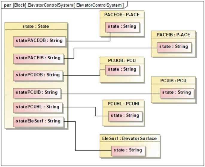
State representing for hierarchical functional model
Fig. 17. 
Enlarged section of the state and state transition behavior of hierarchical functional model
-
(3)
Flow-Processing Behavior Modeling for Hierarchical Functional Model
Based on the method in Sect. 3.3, the flow-processing behavior of the elevator surface control system is modeled. As shown in Fig. 18, the input flow of P-ACE is output to the corresponding functional model under the action of the specific model state and flow-processing behavior, and causes their flow-processing behavior to be executed. Then, the flow-processing behavior of the hierarchical functional model is triggered to change the output flow of the hierarchical functional model.
Fig. 18. 
Enlarged section of flow-processing behavior of hierarchical functional model


4.4 Simulation of Hierarchical Functional Model of Elevator Surface Control System
In the conceptual design of complex systems, it is necessary to simulate the functional model of the system to eliminate errors related to functional logic. Based on the above hierarchical functional model, the functional simulation of the elevator system, including quantitative analysis of the flow-processing behavior of the functional model, is helpful to verify the accuracy of the system functional model. This section gives the simulation cases of the general functional model and the hierarchical functional model respectively, and verifies that the functional model can complete the corresponding traffic behavior in a specific state.
-
(1)
Simulation of General Functional Model
Based on the sub-level functional model and given the expected input, the flow-processing behavior and state transition behavior of the functional model are verified. For example, simulate the PCU functional model: the state of PCU switches from “off” to “NotEngaged” when the input is valid. When the data value of the input flow ‘‘inSOVL” is 28, the data value of “inSOVH” is 0, and the data value of “inSurfPosCmd” equals to 10, the PCU state switches to “Engaged”. At this time, the data value of the output flow "outIsEngaged” of the PCU equals to 1, and the data value of “outSurfPosCmd” is 10 (as expected), as shown in Fig. 19 and Fig. 20.
Fig. 19. 
PCU in ‘‘Engaged’’ state
Fig. 20. 
The flow-processing behavior of PCU in ‘‘Engaged’’ state
-
(2)
Simulation of Hierarchical Functional Model
Initialize the inputs and state of the hierarchical functional model, change the inputs of the system functional model based on the state transition behavior and flow-processing behavior of the hierarchical functional model, track the state transition and flow transition of the corresponding functional model in the system, and then complete the simulation of the functional model. For example, the hierarchical functional model of the elevator surface control system above is simulated: after the inputs of the hierarchical functional model are initialized, the state of the hierarchical functional model is shown in Fig. 21; when the input flows are adjusted to switch the state to a normal working state, verify whether the surface position output instruction is compound expectation at this time. It can be seen from Fig. 22 that when the model is in this state and the given input is 11.5°, the output of the elevator surface position is 11.5°, which is in line with the expected output, and the verification of this state flow-processing behavior is completed. Other state transition behaviors and flow-processing behaviors can be simulated according to the same step, and then the simulation verification of system functions can be completed.
Fig. 21. 
The initialization state of the hierarchical functional model of the elevator surface control system
Fig. 22. 
Surface position control signal output in a certain state


It can be seen from Fig. 19, 20, 21 and 22 that the hierarchical functional model of the elevator surface control system can verify state transition behaviors and flow-processing behaviors. In addition, it can be determined whether the state transition behaviors and flow-processing behaviors of the hierarchical functional model meet expectations, so as to establish an accurate and reliable system functional model.
5 Conclusion
In the conceptual design process of civil aircraft system, accurate establishment of the functional representation of the system serves as the cornerstone for subsequent detailed design. To this end, this paper presents a functional quantitative modeling methodology for civil aircraft systems based on SysML. This approach enables the quantitative expression of the functional model and provides the foundation for its quantitative verification. Specifically, the methodology leverages flow modeling to facilitate quantitative analysis of flow transformation and conversion, while also formally expressing the structure, state, and behavior of the general functional model. Additionally, the approach proposes a method for establishing the hierarchical functional model. To demonstrate the feasibility of the proposed method, the functional modeling of an elevator surface control system is conducted, and the establishment of the functional model and quantitative simulation are succinctly described and demonstrated. The results indicate that the functional modeling methodology described in this paper facilitates the quantitative analysis of the input/output flow of the functional model, thereby providing the necessary foundation for functional completeness verification of the system.
One limitation of the current study is that the proposed method does not address the automated provision of input flows required to complete the state switching of the functional model. As a result, it cannot facilitate automated simulation verification of the state transition and flow-processing behavior of the functional model. To address this shortcoming, future work will involve encapsulating the functional model in the proposed method and developing a system functional simulation model. This will enable the realization of automated simulation verification of complex system function integrity.
References
Kwapień, J., Drożdż, S.: Physical approach to complex systems. Phys. Rep. 515(3–4), 115–226 (2012)
Wang, W., Bi, W., Zhang, A., Fan, Q.: Functional modeling of civil aircraft systems based on MBSE. In: Systems Engineering and Electronics (2021)
Madni, A.M., Sievers, M.: Model-based systems engineering: motivation, current status, and research opportunities. Syst. Eng. 21, 172–190 (2018)
Chen, Y., Tian, B., Li, Z., Xie, Y.: Philosophical thoughts on some basic concepts of civil aircraft development system engineering. Civil Aircraft Des. Res. 000(003), 35–41 (2017)
Pahl, G., Beitz, W., Feldhusen, J.A., Grote, K.H.: Engineering design: a systematic approach (2007)
Gero, J.S., Kannengiesser, U.: The situated function-behaviour-structure framework. Des. Stud. 25(4), 373–391 (2004)
Deng, Y.M., Shu, B.T., Britton, G.A.: A computerized design environment for functional modeling of mechanical products (1999)
Umeda, Y., Ishii, M., Yoshioka, M., Shimomura, Y., Tomiyama, T.: Supporting conceptual design based on the function-behavior-state modeler. AI Edam 10(4), 275–288 (1996)
Goel, A.K., Rugaber, S., Vattam, S.: Structure, behavior, and function of complex systems: the structure, behavior, and function modeling language. In: Artificial Intelligence for Engineering design ANALYSIS and Manufacturing, vol. 23 (2008)
Guo, G., Tang, H., Luo, Y.: Formalized modeling of product functions based on semantics. Comput. Integr. Manuf. Syst. 17(6), 7 (2011)
Chen, Y., Zhao, M., Huang, J.: A state-behavior-function based approach for functional modeling of multi-state systems and its application. In: ASME 2016 International Design Engineering Technical Conferences and Computers and Information in Engineering Conference (2016)
INCOSE SE Handbook Working Group. INCOSE systems engineering handbook v. 3.2. 2. INCOSE-TP-2003-002-03.2.2 (2011)
Author information
Authors and Affiliations
Corresponding author
Editor information
Editors and Affiliations
Rights and permissions
Copyright information
© 2024 The Author(s), under exclusive license to Springer Nature Singapore Pte Ltd.
About this paper

Cite this paper
Ye, S., Chen, Y., Wang, T. (2024). SysML-Based Approach for Functional Quantitative Modeling of Civil Aircraft Systems. In: Jing, Z., Zhan, X. (eds) Proceedings of the International Conference on Aerospace System Science and Engineering 2023. ICASSE 2023. Lecture Notes in Electrical Engineering, vol 1153. Springer, Singapore. https://doi.org/10.1007/978-981-97-0550-4_2
Download citation
DOI: https://doi.org/10.1007/978-981-97-0550-4_2
Published:
Publisher Name: Springer, Singapore
Print ISBN: 978-981-97-0549-8
Online ISBN: 978-981-97-0550-4
eBook Packages: EngineeringEngineering (R0)