
Abstract
There is no authoritative and effective solution for the dynamic response time test of linear differential transformer displacement sensor at home and abroad. This project has carried out special research on the dynamic response time of displacement sensor. Through theoretical analysis and calculation, effective test methods such as free fall test method, spring acceleration test method and excitation coil instantaneous signal excitation method are proposed, and various test methods are effectively verified through relevant experiments.
Access provided by Autonomous University of Puebla. Download conference paper PDF
Keywords
1 Introduction
The linear differential transformer displacement sensor adopts the principle of electromagnetic induction and belongs to a non-contact and loss free measurement method. It has the outstanding characteristics of high measurement accuracy, good stability and strong environmental adaptability [1]. It can be widely used in equipment engineering, automobile manufacturing, aviation, aerospace, power system, industrial process control and other fields. With the increasing development of the application requirements of displacement sensors, the requirements for dynamic characteristics such as sensor output response time are becoming higher and higher [2, 3]. For linear differential transformer displacement sensor, the measurement accuracy and environmental adaptability of the sensor are directly related to the main working performance of the sensor. Therefore, they are the key technical indexes of the sensor. As an important dynamic characteristic index of the sensor, the response time of the sensor is an important parameter to reflect the synchronization between the sensor and the measured displacement. In most applications of displacement sensors, the sensor is required not only to have good static performance such as measurement accuracy, but also to have ideal dynamic response characteristics, that is, the faster the change speed of the measured displacement is, the better, and the shorter the response time is, so as to realize the real-time and accurate measurement and control of the system and process [4, 5]. Therefore, the response time of displacement sensor is a very key technical index, which needs to be measured accurately and effectively to identify the dynamic response ability of displacement sensor.
2 Several Test Methods of Response Time
The response time of the linear displacement sensor is the time required for the signal output of the sensor to detect the change of the displacement of the pull rod. In the actual test process, in order to truly test the response time of the sensor, the movement speed of the detection pull rod should be fast enough that its movement time is negligible relative to the response time of the sensor, so as to avoid that the movement time of the detection pull rod is superimposed on the response time of the displacement output and cannot be effectively eliminated. At present, there has been no effective test method for the dynamic response time of linear displacement sensor at home and abroad. Therefore, this project has carried out the research on several effective test methods for the response time of linear displacement sensor.
-
(1)
Free fall test method
The response time free fall test method is to place the detection pull rod of the displacement sensor in its reciprocating displacement chamber and at the electrical zero point, with the movement trend towards the ground, so that the detection pull rod falls in a free fall mode. At the same time, the whole output process of the sensor from zero point to full scale is recorded with a storable oscilloscope. According to the free fall motion formula: \(S = \frac{1}{2}g \times t^{2}\), the time required for the movement of the pull rod can be calculated. Where, s is the displacement of the pull rod, g is the gravitational acceleration, \(g = 9.8\;{\text{m}}/{\text{s}}^{2}\), and t is the time required to detect the drop of the pull rod from the zero position to the full scale position. For example, the range of a certain type of displacement sensor is 20 mm. According to the free fall formula \(S = \frac{1}{2}g \times t^{2}\), S = 20 mm, t = 63.9 ms is obtained. It can be seen that the movement time of the pull rod in the free falling state is up to 63.9 ms, which is enough to mask the real response time of the sensor. The initial speed of the rod falling freely is 0 m/s, and the speed when moving to the full-scale position is only 0.63 m/s (\(V_{t} = g \times t\)). It can be seen that the moving speed of the detection rod under the condition of free falling is still very limited, and the accurate measurement of the dynamic response time of the sensor can not be fully realized. Therefore, the free fall test method is not suitable for the test object with high requirements for sensor response time (within 10 ms).
-
(2)
Spring acceleration test method
In order to improve the moving speed of the sensor detection pull rod during the test, a light rigid spring is installed on the pull rod and properly installed and fixed, as shown in Fig. 1.
Fig. 1. 
Add spring to the detection pull rod

According to the spring force formula: \(F = K \times X\) (K is the elastic coefficient of the spring and X is the shape variable of the spring) and Newton’s second law formula \(F = m \times a\). The movement time of the displacement detection pull rod from zero position to full scale position under the action of spring can be calculated [6]. In this experiment, the elastic force of the spring at the zero position is 5 kg (49n), and the total mass of a certain type of displacement pull rod and nut is 10 g. The calculated average motion acceleration of the pull rod is \(a = {1 \mathord{\left/ {\vphantom {1 2}} \right. \kern-\nulldelimiterspace} 2}{F \mathord{\left/ {\vphantom {F m}} \right. \kern-\nulldelimiterspace} m}\) = 2450 m/s2, which is far greater than the free fall acceleration of 9.8 m/s2. It is further calculated that under the action of spring, the movement time required to detect the pull rod from zero position to full scale position is about 4 ms. As shown in Fig. 2, the output response time of a certain type of displacement sensor from zero position to full scale position is about 7 ms, including the time occupied by mechanical displacement movement.

Sensor output response curve of spring acceleration test method
It can be seen that although the movement speed of the displacement pull rod is greatly improved under the action of the spring, there is still a movement time of 4 ms. When actually testing the response time of the displacement sensor, the time occupied by the movement of the pull rod should be excluded from the output response time of the sensor. Therefore, the actual dynamic response time of the displacement sensor is about 3 MS. Because the actual movement time of the pull rod is difficult to make a very accurate calculation, the measurement accuracy of the spring acceleration test method can only be controlled within 1.5 ms, which can be used to test the dynamic performance of the displacement sensor with a response time of more than 5 ms. In order to test the dynamic response time of displacement sensor more accurately, the experimental test scheme needs to be further optimized.
3 Excitation Test Method of Instantaneous Signal of Excitation Coil
-
(1)
Experimental principle of excitation signal test method
When the magnetic flux of the transformer is applied to the differential magnetic displacement sensor, the alternating magnetic displacement sensor is made of the magnetic flux of the transformer φ express. In primary and secondary coils φ It is the same. According to Faraday’s law of electromagnetic induction, the induced electromotive forces in the primary and secondary coils are \(e_{1} = - N_{1} \times {{d\varphi } \mathord{\left/ {\vphantom {{d\varphi } {dt}}} \right. \kern-\nulldelimiterspace} {dt}}\), \(e_{2} = - N_{2} \times {{d\varphi } \mathord{\left/ {\vphantom {{d\varphi } {dt}}} \right. \kern-\nulldelimiterspace} {dt}}\). Where N1 and N2 are the turns of primary and secondary coils. \(U_{1} = - e_{{_{1} }}\), \(U_{2} = e_{2}\) (U1 is the effective value of primary coil voltage, U2 is the effective value of secondary coil voltage), let \(K = {{N_{1} } \mathord{\left/ {\vphantom {{N_{1} } {N_{2} }}} \right. \kern-\nulldelimiterspace} {N_{2} }}\), K is called the transformation ratio of transformer. From the above formula, \({{U_{1} } \mathord{\left/ {\vphantom {{U_{1} } {U_{2} }}} \right. \kern-\nulldelimiterspace} {U_{2} }} = - {{N_{1} } \mathord{\left/ {\vphantom {{N_{1} } {N_{2} }}} \right. \kern-\nulldelimiterspace} {N_{2} }} = - K\), that is, the ratio of the effective values of the voltage of the primary and secondary coils of the transformer is equal to its turns ratio, and the phase difference of the voltage of the primary and secondary coils is π [5] (Fig. 3).
Fig. 3. 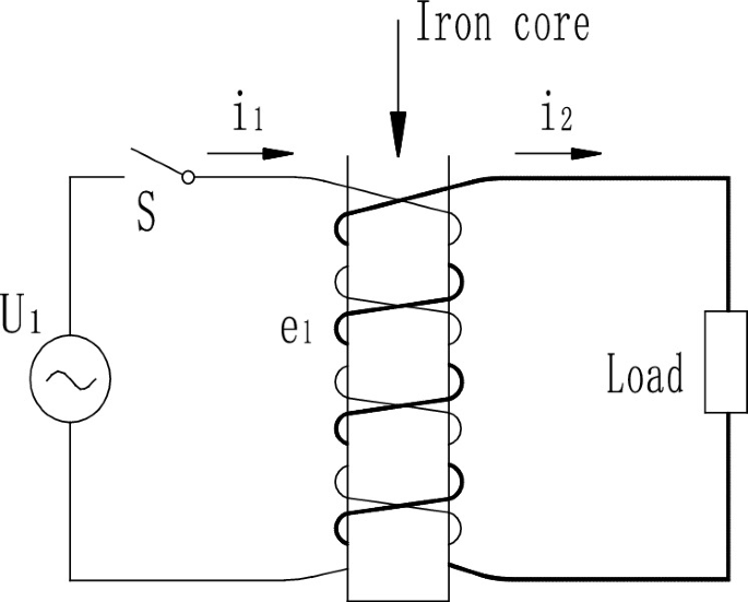
Working principle of differential transformer
According to the above theoretical analysis and practical test, the phase difference between the primary coil excitation and the secondary coil output of the displacement sensor is π, and the corresponding response time is only tens of subtleties (taking the sensor with excitation frequency of 10 kHz as an example, the secondary lags behind the primary is only 50 μs), compared with the response time of the sensor with the response time of milliseconds, it is basically negligible. Therefore, the factors affecting the output response time of the sensor mainly come from the rectification, filtering, amplification and other links of the circuit [7, 8]. Therefore, the detection pull rod of the sensor can be placed at the full-scale position in advance, which is equivalent to the detection pull rod of the sensor moving from the zero position to the full-scale position at a very fast speed, which completely saves the moving time of the pull rod. Then, the instantaneous excitation signal is applied to the primary coil, and the output signal is monitored synchronously at the signal output end of the sensor. When the output signal reaches the full-scale signal amplitude, the time lag behind the starting time of the high level of the excitation step signal is the response time of the displacement sensor, so that the real response time of the displacement sensor can be measured accurately.
-
(2)
Excitation test method of instantaneous signal of excitation coil
In order to accurately test the response time of the displacement sensor, it is necessary to make the sensor operate under reasonable state parameters. The excitation signal selected in this experiment is a sine wave signal with a frequency of 10 kHz and a signal amplitude of 3 V. In the experiment, a fast switch is used to control the output of the excitation signal, and an instantaneous excitation signal is applied at both ends of the primary coil. A storable oscilloscope is used to track and record the complete change process of the output signal waveform of the displacement sensor after the switch is turned on. Track and record the synchronous closing signal of the fast switch with channel 1 of the oscilloscope, and track and record the output signal of the displacement sensor with channel 2 of the oscilloscope. As shown in Fig. 4, the horizontal scanning speed of the oscilloscope is 1 ms/Div. it can be measured from the operation curves of channel 1 and channel 2 of the oscilloscope that the time when the output signal of the sensor lags behind the excitation signal is 2.8 ms, that is, the response time of the displacement sensor is 2.8 ms.
Fig. 4. 
Response time test curve of primary excitation and output signal


4 Conclusion
In this project, various test methods of response time of displacement sensor are comprehensively, systematically and deeply studied. Through theoretical analysis and practical test, a new response time measurement method - excitation coil instantaneous signal excitation test method is creatively proposed, which effectively improves the measurement accuracy of response time. The invention, popularization and application of the measurement method will provide an accurate and effective measurement scheme for the technical identification of the response time of the displacement sensor, and will play a very positive role in promoting the development of the displacement sensor industry and the progress of technology.
References
Lin, X.: Research on Static Characteristics of High Precision Differential Transformer Displacement Sensor. Tianjin University of Technology (2019)
Yu, M.: Research on LVDT Displacement Sensor for Aeroengine. Nanjing University of Aeronautics and Astronautics (2020)
Yu, M., Li, P., Liu, X.: Study on output voltage linearity of dual redundancy LVDT displacement sensor. Electron. Measur. Technol. 43(02), 26–32 (2020)
Gu, M.: Structural Design and Performance Research of Differential Transformer Displacement Sensor. China University of Mining and Technology (2020)
Yan, F.: Measurement Accuracy Analysis and Compensation Method of LVDT for Triaxial Tester. Tianjin University of Technology (2020)
Meng, X., Li, W., Zhang, X., Liu, Y.: Design of a low pressure spring safety valve for radome. Eng. Constr. Des. 14, 136–137 (2020)
Mayunga, S.D., Bakaone, M.: Dynamic deformation monitoring of Lotsane bridge using global positioning systems (GPS) and linear variable differential transducers (LVDT). J. Data Anal. Inf. Process. 09(01) (2021)
Saurav, S., Muthuganesh, M., Chaurasia, P.K., Murugan, S.: Analysis, design, and development of a compact LVDT for in-reactor experiments. IETE J. Edu. 60(2) (2019)
Author information
Authors and Affiliations
Corresponding author
Editor information
Editors and Affiliations
Rights and permissions
Copyright information
© 2023 The Author(s), under exclusive license to Springer Nature Singapore Pte Ltd.
About this paper

Cite this paper
Li, Y. et al. (2023). Dynamic Response Time Measurement Method of Linear Differential Transformer Displacement Sensor. In: Ahmad, I., Ye, J., Liu, W. (eds) The 2021 International Conference on Smart Technologies and Systems for Internet of Things. STSIoT 2021. Lecture Notes on Data Engineering and Communications Technologies, vol 122. Springer, Singapore. https://doi.org/10.1007/978-981-19-3632-6_19
Download citation
DOI: https://doi.org/10.1007/978-981-19-3632-6_19
Published:
Publisher Name: Springer, Singapore
Print ISBN: 978-981-19-3631-9
Online ISBN: 978-981-19-3632-6
eBook Packages: EngineeringEngineering (R0)