
Abstract
Opting for modifications in the existing technology comes with many challenges. The purpose of this project is to deal with one such challenge by analyzing three different aerofoils used in aviation industry and wind turbines industry. The aerofoils chosen for study are NACA 0012, NACA 0018, and S 1046. The flaps are implemented on all the three aerofoils, and values of lift and drag are recorded for angles from 0° to 10° through computational analysis with the help of ANSYS Fluent software. The variation in CL (coefficient of lift) and CD (coefficient of drag) is plotted for different AOAs (angle of attack). From the graphs, we can observe the changes in lift and drag. The study helped us understand the behaviors of the three aerofoils with change in angle of attack. NACA 0018 was found to be more efficient as compared to the other two aerofoils.
Access provided by Autonomous University of Puebla. Download conference paper PDF
Keywords
1 Introduction
Lift is by far the most important characteristic and advantage of an aerofoil. It is because of this characteristic and advantage that they are used extensively in air travel and wind turbines. As air moves around an aerofoil, because of its shape, on the upper side there is high velocity and low pressure, and on the lower side, there is low velocity and high pressure. Because of this, the aerofoil is lifted up and we say that lift is produced. There are primarily two types of aerofoils put to use—i. Symmetric, ii. Asymmetric Yang et al. (2017). In this paper, we have considered three aerofoils and evaluating them by using ANSYS Fluent software package. Below is the graph plotted shown in Fig. 1 for NACA 0012, NACA0018, and S1046 airfoils between y/c versus x/c. Also in Fig. 2 is the bar graph showing the corresponding values of coefficient of lift and drag for the mentioned three aerofoils. In Fig. 2, nomenclature of an aerofoil is shown (Table 1).

Geometric profiles of the aerofoils used and reference taken from Zhang et al. (2016)

Nomenclature of an aerofoil Srinivasa Rao et al. (2018)
Below is the indication of each digit in NACA and S series aerofoils is depicted Senthil Kumar et al. (2018)
-
A.
NACA0012—(0012-il) NACA 0012
-
NACA 0012 airfoil
-
Max thickness 12% at 30% chord.
-
Max camber 0% at 0% chord Ganesh Ram et al. (2014).
-
-
B.
NACA0018—(0018-il) NACA 0018
-
NACA 0018 airfoil
-
Max thickness 18% at 30% chord.
-
Max camber 0% at 0% chord.
-
-
C.
S 1046—(s1046-il) S1046 17% (Danny Howell)
-
Selig S1046 airfoil
-
Max thickness 17% at 30.8% chord.
-
Max camber 0% at 0% chord.
-
2 CFD Analysis
-
A.
CFD Analysis of aerofoils without flaps:
The procedure followed to analyze all the three chosen aerofoils is same which is as follows:
-
I.
The coordinates of the aerofoils are downloaded from airfoiltools.com
-
II.
The coordinated are imported to ANSYS Design Modeler.
-
III.
Surface of the aerofoil is created from these coordinates by using ‘surface from edges’ tool.
-
IV.
A domain is created by sketching a semicircle in the front and rectangle on the rear side and then using the ‘surface from sketches’ tool. Center of the semicircle is taken at 0.1 m of chord, and length of the rectangle is 31 m and height is 20 m above and below x-axis Yan et al. (2019).
-
V.
The aerofoil is removed from domain by using Boolean function.
-
VI.
The domain is split into six faces for better meshing.
-
VII.
While meshing, three named selections are created for convenience—i. Aerofoil, ii. Inlet, iii. Outlet.
-
VIII.
A structured mesh is formed by using biasing feature.
-
IX.
After meshing, solution setup is done with k-ω SST model.
-
X.
Lift and drag force monitors are created.
-
XI.
Initialization is hybrid (Figs. 3, 4, 5, 6 and 7; Table 2).
Fig. 3 
a Lift plot at 0° b Drag plot at 0°
Fig. 4 
Six faces after face split
Fig. 5 
Airfoil removed from domain
Fig. 6 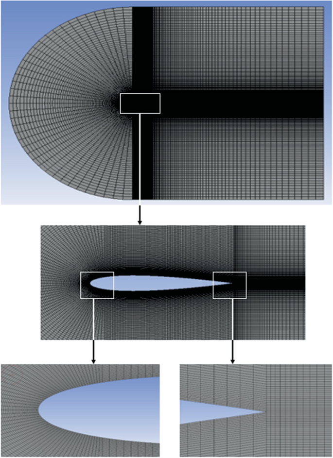
Structured mesh
Fig. 7 
Pressure and velocity contours of aerofoils without flaps
Table 2 Details of CFD analysis
-
I.
-
B.
CFD Analysis of aerofoils with flaps:


With the help of the same software, same mesh, and same setup, all the three airfoils are once again analyzed after implementing simple flaps on them (Figs. 8, 9, 10, 11 and 12; Tables 3 and 4).

S1046 aerofoil pressure and velocity contours at 5° flap deflection

NACA0012 aerofoil pressure and velocity contours at 5° flap deflection

NACA0018 aerofoil pressure and velocity contours at 5° flap deflection

a) CL versus alpha graph b) CD versus alpha graph of S1046, NACA0012, and NACA0018 aerofoils with flaps

Streamlines at different angles of attack (α) below 20° for NACA 0012 (2015)
3 Results
From the above graphs, certain results are being obtained. They are as follows
-
1.
For all the three aerofoils considered in the project—NACA 0012, NACA 0018 and S 1046—initial lift at 0° is lower than that at 10°.
-
2.
At 2° the lift suddenly drops to a very low value for NACA 0012 and S 1046, though it is more than that at 0°. After that as we go on increasing the angle of attack of flaps, lift increases almost proportionally.
-
3.
For NACA 0018, the highest amount of lift is obtained by 2° deflection of flap which is the highest value among all the values of lift obtained.
-
4.
As for the drag, no such unusual behavior is observed. Drag goes on increasing with the increasing angle of attack for all the three aerofoils almost proportionally.
-
5.
Along with higher lift, NACA 0018 also gives higher drag as compared to NACA 0012 and S 1046, as evident from the above graphs.
4 Conclusions
The conclusions drawn from the above study are as follows:
-
1.
As lift increases with increasing angle of attack for all the three aerofoils with flaps, this makes flaps a good modification to these aerofoils.
-
2.
Out of the three aerofoils considered in this project—namely NACA 0012, NACA 0018, and S 1046 – the NACA 0018 with flap is more efficient than the other two aerofoils.
-
3.
Though the drag of NACA 0018 is higher than NACA 0012 and S 1046 (all with flap), the lift obtained is dramatically high. This makes it best suited for implementing on a vertical axis wind turbine.
-
4.
With more modifications to these aerofoils, their lift and drag characteristics can be improved and desired values of lift and drag can be reached so as to obtain higher lift.
-
5.
With higher lift characteristics, these aerofoils will be able to generate more energy in wind turbines and will help reduce the load on conventional energy sources.
-
6.
When implemented on airplane, they will provide more lift helping reduce the use of fuel and will cut the cost of aviation fuel required by a great margin.
5 Future Scope
-
1.
The world is in dire need of improvement in non-conventional energy resources so as to meet the day-by-day increasing energy demand. Wind energy is one of the most reliable resources in this aspect. This project provides a suggestion for the improvement in the conventional designs of airfoils implemented for harnessing wind energy.
-
2.
An airfoil is a basic shape used in any wind turbine blade. It is because of the characteristics of this shape, the way it behaves with respect to incoming wind that makes it most suitable for use in airplanes, wind turbines, etc.
-
3.
With modification in this shape, such as leading edge and trailing edge flaps, slats, and wing tip devices, the lift and drag characteristics can be improved and ultimately the efficiency can be increased. Here we have provided computational analysis of one such modification with the results.
-
4.
In the future, this modification can help us reach the desired configurations and to increase the energy production of wind turbines and lower the fuel consumption manifolds. Wind energy is a clean form of energy, and it does not harm our environment in any way and neither does it add on to the crisis of pollution. This project is a step forward in the direction of upliftment of the ways in which it is harnessed. This will ultimately help mankind in creating a prosperous future for coming many generations.
References
Ganesh Ram RK, Cooper YN, Bhatia V, Karthikeyan R, Periasamy C (2014) Design optimization and analysis of NACA 0012 airfoil using computational fluid dynamics and genetic algorithm. Appl Mech Mater 664:111–116. https://doi.org/10.4028/www.scientific.net/AMM.664.111.
Kurtulus DF (2015) On the unsteady behavior of the flow around NACA 0012 airfoil with steady external conditions at Re=1000. Int J Micro Air Veh 7(3):301–326. https://doi.org/10.1260/1756-8293.7.3.301
Senthil Kumar M, Naiju CD, Patruni H (2018) Experimental study and CFD analysis of an aerofoil structure for automotive body design. SAE Tech Pap 2018. https://doi.org/10.4271/2018-28-0091.
Srinivasa Rao T, Mahapatra T, Chaitanya Mangavelli S (2018) Enhancement of lift-drag characteristics of NACA 0012. Mater Today Proc 5(2): 5328–5337. https://doi.org/10.1016/j.matpr.2017.12.117
Yan Y, Avital E, Williams J, Korakianitis T (2019) CFD analysis for the performance of Gurney flap on aerofoil and vertical axis turbine. Int J Mech Eng Robot Res 8(3):385–392. https://doi.org/10.18178/ijmerr.8.3.385-392
Yang Y, Li C, Zhang W, Guo X, Yuan Q (2017) Investigation on aerodynamics and active flow control of a vertical axis wind turbine with flapped airfoil. J Mech Sci Technol 31(4):1645–1655. https://doi.org/10.1007/s12206-017-0312-0
Zaheer Z, Reby Roy KE, Nair GS, Ragipathi V, Niranjan UV (2019) CFD analysis of the performance of different airfoils in ground effect. J Phys Conf Ser 1355(1). https://doi.org/10.1088/1742-6596/1355/1/012006
Zhang T-T, Huang W, Guo Wang Z, Yan L (2016) A study of airfoil parameterization, modeling, and optimization based on the computational fluid dynamics method. J Zhejiang Univ Sci A 17(8): 632–645. https://doi.org/10.1631/jzus.A1500308
Author information
Authors and Affiliations
Editor information
Editors and Affiliations
Rights and permissions
Copyright information
© 2022 The Author(s), under exclusive license to Springer Nature Singapore Pte Ltd.
About this paper

Cite this paper
Kaushik, V., Wandile, A., Girade, V., Khadse, C. (2022). ‘2D Simulation to Study the Effect of Flaps on Various Aerofoils at Different Angles’. In: Parwani, A.K., Ramkumar, P., Abhishek, K., Yadav, S.K. (eds) Recent Advances in Mechanical Infrastructure . Lecture Notes in Intelligent Transportation and Infrastructure. Springer, Singapore. https://doi.org/10.1007/978-981-16-7660-4_24
Download citation
DOI: https://doi.org/10.1007/978-981-16-7660-4_24
Published:
Publisher Name: Springer, Singapore
Print ISBN: 978-981-16-7659-8
Online ISBN: 978-981-16-7660-4
eBook Packages: EngineeringEngineering (R0)