
Abstract
Wire arc additive manufacturing (WAAM) is an imperative method for fabricating 3D metallic parts. By the large, additive manufacturing (AM) innovation is utilized to prevail over the restriction of conventional subtractive manufacturing (SM) for manufacturing larger parts with a low buy-to-fly ratio. There are mainly three heat sources utilized in WAAM: metal inert gas welding (MIG), tungsten inert gas welding (TIG) and plasma arc welding (PAW). WAAM is picking up a reputation for the manufacturing of 3D parts using metal as raw material but the method is difficult to control because of its implicit residual stress, low hardness, discontinuous deposition, roughness, low grain growth and distortion. These problems create major issues for WAAM since they affect the part’s geometric precision and extremely demean the properties of manufacturing parts. In this review paper, the WAAM process for the manufacturing of 3D metal parts along with its process parameters and their effect is reviewed.
Access provided by Autonomous University of Puebla. Download conference paper PDF
Keywords
1 Introduction
Additive manufacturing (AM) is a method used in the creation of 3D parts with layer-by-layer material deposition [1]. AM was earlier known as rapid prototyping (RP), rapid tooling (RT) and layered manufacturing (LM). AM may be able to fabricate useful items directly from computer-aided design (CAD) data [2]. AM is developed in three phases. First phase is manual prototyping where prototypes are not very sophisticated, and level of complexity is simple. Second stage is soft or virtual prototyping begun between 1975 and 1980. In this stage, computerized models can be stressed, modelled and tested by a computer and the complexity of items is twice as complex as in the past stage [3]. The third phase is rapid prototyping, which started in the mid-1980s, which results in reducing the manufacturing time by using the hard prototype and increase the complexity almost three times higher than the second phase [3].
Despite the fact that there is a couple of variability inside the mechanical behaviour of AM parts which are routinely demonstrated by the heterogeneity and anisotropy developing from the variety in heat supplied [4]. The primary advantages of AM over the traditional conventional methods are high precision, faster manufacturing rate, and reduction in material waste [5]. Most of the added substances utilized were plastic, polymer and ceramic but presently nowadays metals are also being used as raw material in various AM processes. The usage of manufacturing technologies is subordinate to the raw material status during 3D metal printing.
2 Metal Additive Manufacturing
Metal additive manufacturing is known as a deposition of liquid metal in layers. It may be a direct feeding process including combining electrical sources, a movement framework and feedstock based on the wire. It is the improvised form of the fused deposition modelling (FDM) technique. On the basis of raw materials used, metal AM is classified into wire-based, powder-based and sheet-based processes. Among these technologies, the wire-based method leads in terms of structural efficiency and deposition rates. Wire-based methods also suitable for continuous and uncluttered material flow. Hence, wire-based AM is the most suitable for the production of costly components [6]. This technology can proficiently deliver large-scale metal components. However, with regard to accuracy and surface roughness, it is lower than other AM methods [7, 8]. Uses of metal additive manufacturing in recent times increases because of its ability to deliver metal parts at less cost and low buy-to-fly ratio. On the basis of the power source used, metal AM processes can be also classified as:
2.1 Electron Beam Additive Manufacturing (EBAM)
In this method large size, complex and intricate parts are possible to fabricate by an electron beam which uses as a heat source. Also, the use of vacuum in this technique allows the easy deposition of reactive metals like titanium otherwise for the fabrication of reactive materials we required some separate shield arrangement [6] (Fig. 1).

Schematic diagram of EBAM [9]
2.2 Wire and Laser-Based Additive Manufacturing (WLAM)
WLAM is a process of fabricating 3D complex shape products by continuous feeding of wire into the molten metal pool. Uses of high power density in this technology, small and complex characteristics are easily obtained. High cost and incapability of producing large components are the primary limitation of WLAM [6] (Fig. 2).

Schematic diagram of WLAM [10]
2.3 Wire and Arc-Based Additive Manufacturing (WAAM)
In this technique, fabrication of 3D parts was carried out with the help of welding torch to generate weld pool by selecting optimum process parameters and adaptive tool path generating strategy. The main advantage of WAAM over other processes is the high deposition rate which makes this method faster and compatible (Fig. 3).

Schematic diagram of WAAM [11]
Metal inert gas (MIG) [12, 13], tungsten inert gas (TIG) [14,15,16] and plasma arc welding (PAW) [17, 18] are the main source of heat used in the WAAM technology. The afterwards execution of cold metal transfer (CMT) as upgraded MIG it is widely used as the heat source. Due to its capacity to deliver a high rate of deposition with lower heat input, CMT has superior execution than MIG [19, 20]. MIG has four welding modes: globular mode, short-circuit mode, splash mode and pulsed-spray mode. In 1920, Shirizly et al. [21] utilized a fusible electrode to form an overlapping metal deposit. Subsequently, Ujiie et al. [22, 23] created the procedure of making a circular cross section through dynamic weld metal deposition. An offline observing framework was created to permitted a computer-aided design (CAD) format to be sliced to encourage weld deposition in layer-by-layer in an indicated to organize [24] (Fig. 4).

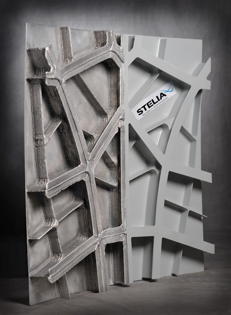
Specimen fabricated by WAAM machine [26]
3 Parameters Affecting the WAAM Technology
3.1 Wire Feed Speed (WFS)
The study shows that the wire feed rate of Al5Si alloy below 10 m/min and above 45 m/min creates a discontinuous deposit. The best regular bead with a 0.1 mm standard deviation is obtained with 35 m/min wire feed speed [25]. It also shows that bead height of Hastelloy X alloy (nickel-based alloy) is linearly related to wire feed rate [27].
3.2 Travel Speed
Travel speed inversely affects the humping defect, melt through depth and bead width. Study shows that an increase in travel speed of Hastelloy X alloy (nickel-based alloy) results decrease in bead width and melt through depth, due to this the roughness is increased [27]. It also shows that the extreme speed at which humping starts in mild steel wire is 0.6 m/min for 0.8 mm wire diameter [28].
3.3 Heat Input
Results show that the decrease in heat input slows down the grain growth rate of ER5356 (aluminium–magnesium alloy). Also, heat supplied alternatively between layers formed small pores and cracks, large-sized grains and relatively low micro-hardness [29]. Bead structure of Ti6Al4V alloy in the first few layers differs along with the deposition height due to changes in the heat dissipation route but later it is insignificant of heat input [30]. Also, microstructure, grain size and crystalline stage of the Ti6Al4V sheet due to impacts of heat input vary along the construction direction. Optimum temperature to get favourable mechanical properties of Ti6Al4V is 200 °C [31].
3.4 Deposition Direction
The hardness of AA5183 aluminium alloy in the horizontal direction is approximately 75 kg/mm2, whereas hardness shown in the vertical direction is about 70–75 kg/mm2. It is also found that the deposition of multilayers from consequent passes gives cracking in weld [32]. Uniform deposition of molten metal depends on the wire feeding angle. A lower value of wire feeding angle (30°–50°) resulting in cracking of deposition of Ti6Al4V alloy, whereas the wire feeding angle of (70°) causes droplets splattering on the side of deposition [33].
3.5 Bulk Deformation
The study shows that the pores larger than 5 µm in diameter of 2319 Al alloy are dispensed with a rolling load of 45 kN [34]. There are two types of roller used in cold working of ER70S-6 steel, slotted roller and profiled roller. Among them, the slotted roller has a high efficiency of distortion elimination and deposition than later one [35].
4 Applications of WAAM
WAAM is suitable for the production of large-sized costly components with high complexity; hence, it is suitable to be used in areas such as aerospace industry, automotive industry, defence industry, naval industry and nuclear industry [36].
The main applications of WAAM technology are given below:
4.1 Aerospace Industries
Manufacturing of titanium and nickel alloys components with high complexity is the main focus in the aerospace industry because subtractive methods seem to be difficult and costly for the production of these material parts [37, 38].
4.2 Nuclear Industry
For manufacturing parts in the nuclear industry, WAAM is an appropriate method because it replaces some less useful nickel parts to stainless steel parts so that cost and weight both are reduced [39].
4.3 Medical Industry
In the medical industry, different alloys of cobalt, titanium and chromium are used for fabricating human vertebra, hip stem implants, dental implants and treatment of bone fracture with the help of WAAM technology [40, 41].
5 Issues and Challenges
5.1 Surface and Material Quality
Excessive heat input is required for achieving a high deposition rate in WAAM but due to high heat input, several challenges like residual stresses and distortions are coming as result, so for the fabrication of large metal components through WAAM these two are the primary concern. To get rid of these problems, post-welding heating is used for releasing residual stress and preheating is used for the problem of surface cracks and distortions.
5.2 Residual Stress and Distortion
Residual stress causes component failure because of uneven heat flow, and also, it is responsible for rough tolerance. For reducing the residual stress, post-processing is applied but the problem of reduced tolerance is remaining. Post-weld heat treatment (PWHT) can be used to reduce the residual stress during the process.
6 Conclusion
Numerous theories on WAAM state that WAAM can essentially decrease costs and enhance manufacturing effectiveness in industrial areas, particularly the aerospace, nuclear industry and automotive areas. Subsequently, numerous researches have focused on upgrading the WAAM process through moderation during 3D printing. Several process variations have been evolving in recent times to improving the microstructure and mechanical properties of the manufactured components. Moreover, the maximum number of alloys like aluminium, titanium and steel are utilized previously in fabricating the component using WAAM technology with fabulous outcomes.
References
Zhou JG (1999) A new rapid tooling technique and its special binder study. Rapid Prototyp J 5:82–88
Shrestha R, Simsiriwong J, Shamsaei N (2019) Fatigue behavior of additive manufactured 316L stainless steel parts: effects of layer orientation and surface roughness. Addit Manuf 4:224–278
Chua CK, Leong KF (2003) Rapid prototyping principles and applications. World Scientific Publishing Co., Pte. Ltd., Singapore
Nimawat D, Meghvanshi M (2012) Using rapid prototyping technology in mechanical scale models. Int J Eng Res Appl 2:215–219
Sodeifian G, Ghaseminejad S, Akbar A (2019) Preparation of polypropylene/short glass fiber composite as fused deposition modeling (FDM) filament. Results Phys 12:205–222
Gibson I (2010) Additive manufacturing technologies. In: Rapid prototyping to direct digital manufacturing
Szost BA, Terzi S, Martina F, Boisselier D, Prytuliak A, Pirling T, Hofmann M, Jarvis DJ (2015) A comparative study of additive manufacturing techniques: residual stress and microstructural analysis of CLAD and WAAM printed Ti–6Al–4V components. Mater Des 8:684–699
Li JZ, Alkahari MR, Rosli NAB, Hasan R, Sudin MN, Ramli FR (2019) Review of wire arc additive manufacturing for 3D metal printing. Int J Autom Technol 13:346–353
AM_EBDM_Illustration @ Additivemanufacturing.Com [Online]. Available: https://additivemanufacturing.com/wp-content/uploads/2015/08/AM_EBDM_Illustration.jpg
0104-9224-Si-0104-9224SI220406-Gf01 @ www.Scielo.Br [Online]. Available: https://www.scielo.br/img/revistas/si/v22n4//0104-9224-si-0104-9224SI220406-gf01.jpg
10033_2018_276_Fig1_HTML @ Media.Springernature.Com [Online]. Available: https://media.springernature.com/original/springer-static/image/art%3A10.1186%2Fs10033-018-0276-8/MediaObjects/10033_2018_276_Fig1_HTML.png
Zhang Z, Sun C, Xu X, Liu L (2018) Surface quality and forming characteristics of thin-wall aluminium alloy parts manufactured by laser assisted MIG arc additive manufacturing. Int J Light Mater Manuf 6:494–506
Xiong J, Lei Y, Chen H, Zhang G (2016) Fabrication of inclined thin-walled parts in multi-layer single-pass GMAW-based additive manufacturing with flat position deposition. J Mater Process Tech 3:278–310
Bai JY, Yang CL, Lin SB, Dong BL, Fan CL (2015) Mechanical properties of 2219-Al components produced by additive manufacturing with TIG. Int J Adv Manuf Technol 2:424–484
Baufeld B, Van Der Biest O, Gault R (2010) Additive manufacturing of Ti–6Al–4V components by shaped metal deposition: microstructure and mechanical properties. Mater Des 31:106–111
Martina F, Ding J, Williams S, Caballero A, Quintino L (2018) Tandem metal inert gas process for high productivity wire arc additive manufacturing in stainless steel. Addit Manuf 4:594–684
Aiyiti W, Zhao W, Lu B, Tang Y (2013) Investigation of the overlapping parameters of MPAW-based rapid prototyping. Rapid Prototyp 12:165–172
Wu CS, Wang L, Ren WJ, Zhang XY (2014) Plasma arc welding: process, sensing, control and modeling. Manuf Process 16:74–85
System MW, Chen X, Su C, Wang Y, Noor A (2018) Cold metal transfer (CMT) based wire and arc additive. Surf Investig 12:1278–1284
Cong B, Ding J, Williams S (2015) Effect of arc mode in cold metal transfer process on porosity of additively manufactured Al-6.3% Cu alloy. Adv Manuf Technol 76:1593–1606
Shirizly A, Dolev O (2018) From wire to seamless flow-formed tube: leveraging the combination of wire arc additive manufacturing and metal forming. Miner Met Mater Soc 7:585–594
Ujiie A (1971) U.S. Patent No. 3,558,846. U.S. Patent and Trademark Office, Washington, DC
Ujiie A (1973) U.S. Patent No. 3,746,833. U.S. Patent and Trademark Office, Washington, DC
Ribeiro F (1994) Metal based rapid prototyping for more complex shapes. Comput Technol Weld 8:724–735
Ortega AG, Galvan LC, Mezrag B (2017) Effect of process parameters on the quality of aluminium alloy Al5Si deposits in wire and arc additive manufacturing using a cold metal transfer process. Sci Technol Weld Join 6:1743–2936
Abe T, Mori D, Sonoya K, Nakamura M, Sasahara H (2019) Control of the chemical composition distribution in deposited metal by wire and arc-based additive manufacturing. Precis Eng 55:231–239
Dinovitzer AM, Chen X (2018) Effect of wire and arc additive manufacturing (WAAM) process parameters on bead geometry and microstructure. Addit Manuf 34:997–1013
Adebayo A, Mehnen J, Tonnellier X (2012) Limiting travel speed in additive layer manufacturing. Trend Weld Res 3:884–892
Su C, Chen X, Gao C, Wang Y (2019) Effect of heat input on microstructure and mechanical properties of Al-Mg alloys fabricated by WAAM. Appl Surf Sci 486:431–440
Wu B, Ding D, Pan Z, Cuiuri D, Li H, Han J, Fei Z (2017) Effects of heat accumulation on the arc characteristics and metal transfer behavior in wire arc additive manufacturing of Ti6Al4V. J Mater Process Technol 54:112–140
Wu B, Pan Z, Ding D, Cuiuri D, Li H (2018) Effects of heat accumulation on microstructure and mechanical properties of Ti6Al4V alloy deposited by wire arc additive manufacturing. Addit Manuf 94:713–740
Horgar A, Fostervoll H, Nyhus B, Ren X, Eriksson M, Akselsen OM (2018) Additive manufacturing using WAAM with AA5183 wire. J Mater Process Technol 259:68–74
Wu Q, Lu J, Liu C, Shi X, Ma Q, Tang S (2017) Obtaining uniform deposition with variable wire feeding direction during wire-feed additive manufacturing obtaining uniform deposition with variable wire feeding direction during wire-feed additive manufacturing. Mater Manuf Process 6914:1532–2475
Gu J, Ding J, Williams SW, Gu H, Ma P (2016) The effect of inter-layer cold working and post-deposition heat treatment on porosity in additively manufactured aluminum alloys. J Mater Process Technol 230:26–34
Colegrove PA, Coules HE, Fairman J, Martina F, Kashoob T, Mamash H, Cozzolino LD (2013) Microstructure and residual stress improvement in wire and arc additively manufactured parts through high-pressure rolling. J Mater Process Technol 213:1782–1791
Thompson MK, Moroni G, Vaneker T, Fadel G, Campbell RI, Gibson I, Bernard A, Schulz J, Graf P, Ahuja B, Martina F (2016) Design for additive manufacturing: trends, opportunities, considerations, and constraints. CIRP Ann Manuf Technol 65:737–760
Merlin PW (2009) Design and development of the blackbird: challenges and lessons learned. In: 47th AIAA aerospace sciences meeting including the new horizons forum and aerospace exposition, pp 1–38
DEFACTO_STELIA_PANEL-752x1024 @ 3dprintingindustry.Com [Online]. Available: https://3dprintingindustry.com/wp-content/uploads/2018/02/DEFACTO_STELIA_PANEL-752x1024.jpg
Abe T, Sasahara H (2016) Dissimilar metal deposition with a stainless steel and nickel-based alloy using wire and arc-based additive manufacturing. Precis Eng 45:387–395
Buchanan C, Gardner L (2019) Metal 3D printing in construction: a review of methods, research, applications, opportunities and challenges. Eng Struct 180:332–348
Medical-Implants_feature @ I0.Wp.Com [Online]. Available: https://i0.wp.com/www.pddinnovation.com/wp-content/uploads/2017/11/medical-implants_feature.jpg?fit=584%2C437&ssl=1
Author information
Authors and Affiliations
Corresponding author
Editor information
Editors and Affiliations
Rights and permissions
Copyright information
© 2021 The Author(s), under exclusive license to Springer Nature Singapore Pte Ltd.
About this paper

Cite this paper
Chaurasia, M., Sinha, M.K. (2021). Investigations on Process Parameters of Wire Arc Additive Manufacturing (WAAM): A Review. In: Singari, R.M., Mathiyazhagan, K., Kumar, H. (eds) Advances in Manufacturing and Industrial Engineering. ICAPIE 2019. Lecture Notes in Mechanical Engineering. Springer, Singapore. https://doi.org/10.1007/978-981-15-8542-5_74
Download citation
DOI: https://doi.org/10.1007/978-981-15-8542-5_74
Published:
Publisher Name: Springer, Singapore
Print ISBN: 978-981-15-8541-8
Online ISBN: 978-981-15-8542-5
eBook Packages: EngineeringEngineering (R0)