
Abstract
Zr–Sn–Nb alloy is an important field of Zirconium alloy for high burn-up Pressurized Water Reactors (PWRs). This article reports the microstructure evolution of Zr–0.5Sn–0.15Nb–0.75FeV alloy tube during fabrication. The morphologies of grain and second phase particles (SPPs), their shape, size and distribution have been studied in detail using optical microscopy (OM), scanning electron microscopy (SEM) and transmission electron microscopy (TEM). The microstructure evolution is as follows: lath martensite (β-quenching) → heterogeneous deformation structure and dynamically recrystallized grain (hot extrusion) → heterogeneous deformation structure (cold rolling) → heterogeneous recrystallized grain (intermediate annealing) → homogeneous deformation structure (finishing rolling) → homogeneous fully recrystallized structure (final annealing). SPPs in the hot extruded tubes tend to precipitate along the direction of deformation. With the processing and heat treatment of the alloy, the SPPs are distributed more dispersively. At last, homogeneous and fine SPPs are distributed on Zr matrix uniformly. It can be found that two kinds of SPPs exist in the products. One are ZrFeV SPPs without Nb and the other are ZrNbFeV SPPs containing a small amount of Nb. Fe/V in SPPs are similar to the Fe/V in addition of alloying element and the results show Fe and V can precipitate fully in the form of SPPs.
Access provided by CONRICYT-eBooks. Download conference paper PDF
Keywords
Introduction
Zirconium alloys are the only cladding material used in the PWRs due to their excellent neutron economy, superior corrosion resistance and favorable mechanical properties under irradiation [1]. Among them, Zircaloy-4 alloy has been used as nuclear fuel cladding materials for several decades without any significant problem in PWRs. However, more advanced Zirconium alloys are recently required for the more severe operating conditions such as higher burn-up, increased operation temperature, and different pH operation conditions. Therefore, many works have been done for developing better Zr-based alloy, and Zr–Sn–Nb alloy is an important field for high burn-up PWRs. Many researches about Zr-2, Zr-4 and Zr–Nb alloy show that the processing and heat treatment can affect microstructure and strongly influence the properties [2,3,4]. However, the researches about the processing and microstructure of Zr–Sn–Nb alloys are rare. In this article, the microstructure evolution of Zr–0.5Sn–0.15Nb–0.75FeV alloy tubes has been studied in detail using OM, SEM and TEM.
Experimentation
The materials selected for experimentation were Zr–0.5Sn–0.15Nb–0.75FeV alloy tubes. They were prepared by following major stages: (a) forging ingot in the region of 900–1100 ℃; (b) quenching the forged billets in the region of 1000–1050 ℃; (c) extruding tubes in the region of 600–700 ℃; (d) three passes cold rolling and processing annealing, which is called P1, P2, P3 cold rolling and processing annealing in this paper; (e) finishing rolling and final annealing. The process is shown briefly in the Fig. 1. In order to study microstructure evolution during fabrication of alloy tube, some specimens were selected from different processing stages.

Preparation of Zr–Sn–Nb alloy tubes
A Leica MeF3A optical microscopy equipped with an optical polarizer was employed to characterize the morphologies of grain, and the observation surface is AD-RD side and TD-RD side, as is shown in Fig. 2. Before OM observation, specimens were mechanically ground using SiC paper (4000# in the final step) and etched in a mixed solution composed of 10% HF + 45% HNO3 + 45% H2O by rubbing for 30 s with a cotton wool and then electrolytic colored by 5% H2SO4.

AD-RD side and TD-RD side
A FEI Nova 400 field emission scanning electron microscopy analysis system (Channel 5, HKL Technology-Oxford Instruments) was employed to analyze shape, size and distribution of SPPs, and the observation surface is AD-RD side. Before SEM observation, specimens were mechanically ground using SiC paper (4000# in the final step) and etched in a mixed solution composed of 10% HNO3 + 30% HF + 60% C3H8O3 by rubbing for 5–10 s with a cotton wool and rinsed in HNO3 to skim off the oil on the surface.
A JEOL-200CX transmission electron microscopy equipped with Energy dispersive X-ray spectroscopy (EDS) analysis system was employed to analyze shapes, distributions and composition of SPPs, and TEM specimens were prepared by electro-polishing in TENUPOL-2twin-jet electropolisher. The electropolishing solution consisted of HClO436 mL + CH3CH2OH 264 mL working at a voltage of 50 V and a temperature of −40 ℃.
Results and Discussion
-
Metallographic Structure Evolution. Figure 3 shows the metallographic structure evolution during process after β-quenching. The metallographic image after β-quenching (Fig. 3a) shows a typical martensite structure. After homogenization treatment at β-region, Zr-based alloy was cooled in water. And cooling rate value was very high. So the martensitic transformation occurs [5]. There are three kinds of typical grain existing in the tubes obtained from hot extrusion (Fig. 3b). The first kind is fibrous grain paralleled to the rolling direction. These grains are thin and long. The second kind is fine dynamic recrystallized grains. It shows that dynamic recrystallization occurs during the hot extrusion. The third kind is belt-shaped heterogeneous deformation structure. There are twins found in this kind of structure. The belt-shaped heterogeneous deformation structure and fibrous grains also are found in P1 and P2 cold rolled tubes (Fig. 3c, e). Main reason for heterogeneous deformation structure is as follows. At room temperature, the zirconium alloy is α-Zr, which is hexagonal close packed structure, and there are few independent enabled slip systems during the deformation process. It leads the anisotropy of mechanics. So the heterogeneous deformation structure appears frequently during the preparation of Zr-based alloy [6, 7]. The microstructure of P1 and P2 processing annealed tubes shows that most of grains are aquiaxed, but a small amount of belt-shaped deformation structure appears (Fig. 3d, f). This phenomenon is related to the recrystallization driving force. During the annealing process, recrystallization prefers to occur in structure with large deformation. But the number of the dislocations in heterogeneous deformation structure is very limited. It cannot provide enough energy for recrystallization. So recovery occurs during the annealing. Because the grain is broken and a large amount of crystal defects and deformation energy will be introduced, the average size of grains in P2 processing annealed tubes is less than the average size of grains in P1 processing annealed tubes. Microstructure of P3 cold rolled tubes and finishing rolled tubes show that a large number of fine fibrous grain appear, and heterogeneous deformation structure disappears (Fig. 3g, i). It indicates that the heterogeneous deformation structures are highly deformed under the strong continuous deformation during continuous cold rolling process.
Fig. 3 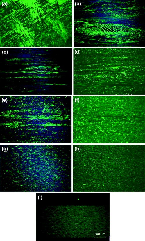
Metallographic structure evolution of AD-RD side during fabrication: a β-quenching; b hot extrusion; c P1 cold rolling; d P1 processing annealing; e P2 cold rolling; f P2 processing annealing; g P3 cold rolling; h P3 processing annealing; i finishing rolling

Figure 4 shows the metallographic structures of AD-RD side and TD-RD side of the products. After a series of processing and heat treatment, a number of fine equiaxed crystal grains distribute uniformly. The well-recrystallized zirconium alloy tubes could be prepared by the present fabrication technology.

Metallographic structure of products: a TD-RD side; b AD-RD side
-
SPPs Evolution. The solid solutions in α-Zr of main alloy elements are very low, so the precipitation and growth of SPPs will occur in the preparation of Zr-based alloy tubes. Some researches suggest that corrosion resistance, grain growth behavior, mechanical properties and irradiation behaviors are strongly influenced by the behaviors of SPPs [8,9,10]. Figure 5 shows the morphologies of SPPs in every processing. The precipitations of SPPs mainly occur in the processing and heat treatment after β-quenching, so the hot extruded tubes is chosen as the initial stage. As is shown below, SPPs in the hot extruded tubes tend to precipitate along the direction of deformation. The process of SPPs precipitation may has some connection with the working temperature of hot extrusion. Because cold rolling produces rolling streamline structure, the distribution of SPPs also shows obvious belt-shaped distribution (Fig. 5b). After P1 processing annealing, the SPPs is slightly dispersed (Fig. 5c). With the processing and heat treatment of the alloy, the SPPs distribute more dispersively. At last, homogeneous and fine SPPs distribute in Zr matrix uniformly. This suggests that deformation can further improve microstructure uniformity of Zr-based alloy.
Fig. 5 
Morphology evolution of SPPs: a hot extrusion; b P1 cold rolling; c P1 processing annealing; d P2 cold rolling; e P2 processing annealing; f P3 cold rolling; g P3 processing annealing; h finishing rolling; i final annealing

Micro image analysis system (MIAS) is used to analyze the size distribution of SPPs. Figures 6 and 7 show the results. The sizes of SPPs are distributed in the range of 10–150 nm mainly. The mean diameters are distributed in the range of 73–96 nm. This suggests that the whole process of processing can control the size of SPPs effectively. In addition, the volume fractions of SPPs maintain within a narrow range during the fabrication, all in the range of 1.13–2.73%. This shows that the SPPs have precipitated fully during the process. The average size of SPPs in the annealed tube is generally bigger than the SPPs in the cold-rolled tube. The number of the SPPs in the range of 10–50 nm has fallen and the number of the SPPs above 100 nm has risen. It indicates small SPPs will grow during the process of annealing.

Size distribution of SPPs in different processing stages: a P1 cold rolling; b P1 processing annealing; c P2 cold rolling; d P2 processing annealing; e P3 cold rolling; f P3 processing annealing; g finishing rolling; h final annealing

Volume fractions and mean diameters of SPPs in different processing stages: 1-P1 cold rolling; 2-P1 processing annealing; 3-P2 cold rolling; 4-P2 processing annealing; 5-P3cold rolling; 6-P3 processing annealing; 7-finishing rolling; 8-final annealing
Figure 8 shows the microstructure of products obtained from TEM. It’s obvious that homogeneous and fine SPPs distribute on Zr matrix uniformly. The analysis of SPPs composition obtained from EDS, which is shown in Fig. 9, shows that two kinds of SPPs exist in the tubes. One is the ZrFeV SPPs without Nb, and the other is a ZrNbFeV SPPs containing a small amount of Nb. All the SPPs selected for EDS analysis contain V, which is related to the nature of V. Solubility of Fe, Cr and V in α-Zr are very low. These elements tend to form the second phase particles, and Fe/V in SPPs are similar to the Fe/V in addition of alloying element, and this shows that Fe and V precipitate fully in the form of SPPs.

Microstructure of products obtained from TEM a low magnification; b high magnification

The relation between Nb and other elements of SPPs in products
Conclusion
-
(1)
The microstructure evolution of Zr–0.5Sn–0.15Nb–0.75FeV alloy tubes during fabrication is as follows: lath martensite (β-quenching) → heterogeneous deformation structure and dynamically recrystallized grain (hot extrusion) → heterogeneous deformation structure (cold rolling) → heterogeneous recrystallized grain (intermediate annealing) → homogeneous deformation structure (finishing rolling) → homogeneous fully recrystallized structure (final annealing).
-
(2)
SPPs tend to precipitate along the direction of deformation after hot extrusion. With the processing and heat treatment of the alloy, the SPPs are distributed more dispersively. At last, homogeneous and fine SPPs are distributed on Zr matrix uniformly.
-
(3)
There are two kinds of SPPs existing in the products. One are ZrFeV SPPs without Nb, and the others are ZrNbFeV SPPs containing a small amount of Nb. Fe/V in SPPs are similar to the Fe/V in addition of alloying element, and this shows Fe and V precipitate fully in the form of SPPs.
References
H.J Yong, K.O Lee, H.G. Kim, Correlation between microstructure and corrosion behavior of Zr–Nb binary alloy. J. Nucl. Mater. 302(1), 9–19 (2002)
A. Miquet, D. Charquet, Solid state phase equilibria of Zircaloy-4 in the temperature range 750–1050 ℃. J. Nucl. Mater. 105, 132–141 (1982)
W. Zhao, B. Zhou, Z. Miao et al, Studies of new zirconium alloys. Rare Metal Mater. Eng. 30(6), 19–23 (2001)
J.P. Mardon, D. Charquet, J. Senevat, Influence of composition and fabrication process on out-of-pile and in-pile properties of M5 alloy (2000)
R.A. Holt, The beta to alpha phase transformation in Zircaloy-4. J. Nucl. Mater. 35, 322–334 (1970)
F. Wagner, N. Bozzolo, O. Van Landuyt, et al., Evolution of recrystallisation texture and microstructure in low alloyed titanium sheets. Acta. Mater. 50, 1245–1259 (2002)
S.K. Sahoo, V.D. Hiwarkar, I. Samajdar, G.K. Dey, D. Srivastav, R. Tiwari, S. Banerjee, Heterogeneous deformation in single-phase Zircaloy 2. Scripta Mater. 56, 963–966 (2007)
W. Liu, Q. Li, B. Zhou, et al., Effect of heat treatment on the microstructure and corrosion resistance of a Zr–Sn–Nb–Fe–Cr alloy. J. Nucl. Mater. 341, 97–102 (2005)
J.Y. Park, B.K. Choi, Y.H. Jeong, et al., Corrosion behavior of Zr alloys with a high Nb content. J. Nucl. Mater. 340, 237–246 (2005)
B.X. Zhou, M.Y. Yao, Q. Li, et al., Nodular corrosion resistance of Zr–Sn–Nb alloy. Rare Metal Mat. Eng. 36, 1317–132 (2007)
Author information
Authors and Affiliations
Corresponding author
Editor information
Editors and Affiliations
Rights and permissions
Copyright information
© 2018 Springer Nature Singapore Pte Ltd.
About this paper

Cite this paper
Wu, Z., Yang, Z., Yi, W., Zhao, W. (2018). Microstructure Evolution During Fabrication of Zr–Sn–Nb Alloy Tubes. In: Han, Y. (eds) Advances in Energy and Environmental Materials. CMC 2017. Springer Proceedings in Energy. Springer, Singapore. https://doi.org/10.1007/978-981-13-0158-2_12
Download citation
DOI: https://doi.org/10.1007/978-981-13-0158-2_12
Published:
Publisher Name: Springer, Singapore
Print ISBN: 978-981-13-0157-5
Online ISBN: 978-981-13-0158-2
eBook Packages: EnergyEnergy (R0)