
Abstract
Tribology is a relatively new area and is defined as the science and technology of the interacting surfaces when they are in relative motion with respect to each other. Among various tribological processes wear is an important area of research. It is defined as the removal of material from either one surface or both the surface when they are in sliding, rolling or in impact contact respectively. There are several types of wear such as adhesive, abrasive, corrosive and fatigue respectively which takes place between the two interacting surfaces. Composite is a combination of two or more compounds thus leading to a development of new material which shows improved properties as compared to the base material. Nanocomposite has the size of each phase in the range of 1–1000 nm, frequently it lies between 1–100 nm. There are several types of nanocomposites such as Polymer Matrix Nanocomposites (PMNCs), Metal Matrix Nanocomposites (MMNCs) and Ceramic Matrix Nanocomposites (CMNCs) etc. Among all, MMNCs has gained much importance because it shows high values of mechanical parameters as compared to PMNCs and CMNCs respectively. MMNCs consist of metal as matrix and ceramic as reinforcement. A lot of researcher have studied the wear behavior of various metals, ceramics and polymers however no systematic attempt has been made to study the wear behavior of composite and nanocomposites especially MMNCs. The present chapter focuses on the wear, its mechanism, types of wear and analysis of wear debris. Apart from this a discussion is also done on the composites, nanocomposites, types of nanocomposites. Wear behavior of metals, ceramics and polymers is also described along with a special focus on iron-alumina metal matrix nanocomposites and a mechanism to reduce the overall wear rate in any system.
Access provided by CONRICYT-eBooks. Download chapter PDF
Keywords
2.1 Wear
The expulsion of material from either of two strong surfaces in relative movement is termed as wear. Wear can also be defined as surface damage, because of material relocation with no net change in weight or volume. It happens as a natural result and for the most part through surface interactions at severities. It is a system response and is not a material property. Interface wear is firmly commanded by working conditions. Wear can be either desirable or undesirable. Desirable instances of wear incorporate machining, polishing, shearing, and writing with a pencil, whereas undesirable cases incorporate all machine applications, for example, gears, bearings, cams, and seals. At times, it is mistakenly expected that high friction wear implies high wear rates, but this is not valid. Interfaces with solid lubricants and polymers generally indicate low friction, however high wear. On the other hand, ceramics show moderate friction with extremely low wear. In some segregated cases, friction and wear might be corresponded. On an overall basis, friction and wear are two distinct system responses [1].
2.2 Types of Wear
Wear occurs either by a chemical process or by a mechanical process or by an amalgamation. In most of the applications, it is accelerated by thermal processes. In our day to day applications, wear is classified on the basis of (a) mechanism and (b) severity of material removal. Nonetheless, on the basis of mechanism employed, it can be extensively arranged in four principle forms:
-
(a)
Adhesive wear
-
(b)
Abrasive wear
-
(c)
Corrosive wear
-
(d)
Fatigue wear
2.2.1 Adhesive Wear
Adhesive wear takes place as a result of micro-junctions produced by welding between two contrasting severities on rubbing surfaces of the counter frames. Load that is applied to the contacting severities is so great that they distort and stick to each other forming micro-joints. Motion of two rubbing counter bodies leads to the generation of rift in between the micro-joints. Welded particle ruptures in the non-deformed regions, thereby leading to transportation of some parts by its counter body. This effect is called as galling or scuffing. At the point when a significant area of the rubbing surfaces adheres, a seizure effect is produced.
There are numerous mechanisms that are present for the development of wear particles. Archard’s theory of sliding wear states that shearing of the severity junctions can occur in one of the two bodies depending upon the relative magnitude of interfacial adhesion strength and the shearing strength of surrounding native regions. Fragments of wear occur due to such shearing, whereas, when shearing occurs along the interface, no wear occurs. In another mechanism, the detachment of wear fragments results from the plastic shearing of successive layers of an asperity contact. Due to adhesion, the separated fragment may be conveyed to the mating surface. Furthermore, sliding also leads to the development of fragments. Attachment of fragments indicates that the bond between the surface and the fragment is strong, while the development of loose particles suggests that there is a weak bond between the mating surfaces. Owing to oxidation, chemical changes in the fragment occurs, which may decrease the adhesive strength and promote development of loose particles. Residual elastic energy of adherent fragments may sometimes be accountable for the development of loose particles. Fragment is heavily stressed when it is captured between the two mating surfaces and as the other surface continues to travel, only the residual elastic stresses are left behind. In case the elastic energy overcomes the adhesive energy in magnitude, then the fragment forms a loose wear particle.
A simple model of adhesive wear states that the amount of wear is directly proportional to the applied load (W) and the sliding distance (x) and is inversely proportional to the hardness (H) of the surface being worn away. The volume of wear v is given by
where k is a previously introduced wear coefficient dependent on the material pair and their surface cleanliness. The above Eq. (2.1) can be derived using Archard’s law [1].
The factors which decrease adhesive wear are as follows:
-
Harder rubbing materials.
-
Lower load.
-
Contaminated rubbing surfaces.
-
Presence of solid lubricants.
-
Anti-wear additives in oil.
-
Presence of a lubrication oil.
2.2.2 Abrasive Wear
Abrasive wear also called cutting wear, takes place when a solid object is loaded against particles of a material that have a relatively greater hardness. This results in wedging, plowing, and cutting; an example of this problem is the wear of shovels on earth-moving machinery. The extent of abrasive wear is far bigger than realized. Abrasive wear takes place in the presence of hard particles [2]. There are a number of wear mechanisms acting in a sliding body which shows different properties [3].
Abrasive wear is caused by the path of relatively hard particles/asperities over a surface. A few well-known reasons of abrasive wear mechanisms are stated below:
-
Micro-cutting: It occurs when a hard particle cuts the softer material. Cut material is removed in the form of wear debris.
-
Micro-fracture: It generally occurs in brittle materials, e.g., ceramic material. The fracture of the worn surface occurs due to the merging of a number of smaller cracks.
-
Micro fatigue: When a ductile material is scraped by a blunt particle or asperity then the worn surface is repeatedly loaded and unloaded. In this case, the failure occurs due to fatigue.
-
Removal of material grains: It occurs in materials (i.e., ceramics) having relatively weak grain boundaries.
Different type of abrasive wear mechanisms are as follows:
-
Two-Body Abrasion
This wear mechanism occurs when two intermingling asperities are in physical contact, and where one of them is harder than other. Due to normal load, the harder asperities penetrate into softer surface and thus produce plastic deformations. To slide, the material is displaced/removed from the softer surface by a combination of micro-plowing and micro-cutting.
-
Three-Body Abrasion
This type of abrasion occurs when a material is removed from a softer surface by hard loose particles, which are allowed to move and also slide over the surface, as they are not detained inflexibly. The hard particles might be created locally by oxidation or wear from the components of tribological framework. Iron oxides wear debris produced during adhesive wear brings on additional damage due to abrasion. Due to the influence of rolling, abrasive wear constant is lower in three body abrasion as compared to two-body abrasion.
From the estimations of wear constants, it is evident that the wear rate is lesser in three-body abrasion than in two-body abrasion. The reduction in three-body abrasion occurs due to energy consumed in rolling motion of free hard particles.
It was initially believed that abrasive wear due to grits or hard severities bears a resemblance to cutting by a series of file or machine tools. However, microscopic investigation has revealed that the cutting process is just estimated by the sharpest of grits and numerous other more subsidiary mechanisms involved. The particles or grits may expel material by micro-fracture, micro-cutting pulled out of individual grains [4] or fast-tracked fatigue by repeated deformations as outlined in the figure. In some practical applications such as polishing process, the abrasive particles are desired or useful since it produces refined or polished surfaces. The ridges made during abrasion process turn out to be flattened after some sliding distance and are fractured due to repeated cyclic system [5, 6].
Figure 2.1a represents cutting, where a sharp grit or hard asperity cuts the softer surface. The cut material is removed as wear debris. Fracture of the worn surface may occur, which is shown in Fig. 2.1b, if the scraped material is brittle, e.g., ceramic. In this case, wear debris is the consequence of crack intersection. When a ductile material is scraped by a blunt grit then in this case, cutting is not likely and the surface that is worn is repeatedly deformed as shown in Fig. 2.1c. In this instance, wear debris is the outcome of metal fatigue. The final mechanism illustrated in Fig. 2.1d signifies grain pullout or grain detachment. This mechanism relates generally to ceramics, where there is a comparatively weak boundary between grains. In this mechanism, the complete grain is lost in the form of wear debris.

Mechanisms of abrasive wear: micro-cutting, fracture, fatigue, and grain pullout [7]
It has been found that the Archard wear equation derived for adhesive wear is also useful in the demonstration of abrasive wear. Consider, for an instance, the case of an abrasive surface that consists of conical severities of included angle α that plows through the surface of a softer material. Figure 2.2 illustrates abrasive wear by conical indentation. By travelling a distance x, the volume of the material removed is given by,

Abrasive wear by conical indentation
But, \(d = a\,\tan \,\alpha\)
Therefore,
Assuming that the material has yielded under normal load \(= 1/2\pi \alpha^{2} H\), where H is the hardness of the softer material. The volume of the displaced material in terms of load is expressed as:
Since it is observed that all traversals of abrasive wear do not produce loose wear debris, so Eq. (2.4) can be modified as
where k is the proportion of events that actually result in the formation of wear particles, So
where \(k_{\text{abr}} = k\,\tan \alpha /\pi\) and is a non-dimensional wear coefficient that depends on the geometry of the abrading particle and usually ranges between 10−6 to 10−1.
2.2.3 Corrosive Wear
When sliding prevails in a corrosive atmosphere, then it is known as corrosive wear. It is also known as chemical wear. Since the most corrosive medium in the air is oxygen, it is generally known as oxidative wear. The oxides, which are in the form of corrosive products, create a dense film on the surface, and sliding activity helps it to wear away the particles. In the non existence of sliding action, the film be likely to seize the corrosion. Thus, corrosive wear necessitates both the sliding action (rubbing) and chemical reaction (corrosion). Oxide film occasionally averts the metal-to-metal contact and hence diminishes against the stark adhesion-enhanced wear, which would otherwise occur. Corrosive wear is used in many industries such as mineral processing, mining, slurry handling, and chemical processing.
At higher temperature, oxygen can interact with the sliding surface and form oxides known as oxidative wear. For instance, oxidation of Inconel (nickel–chromium alloys containing some iron) occurs at 100 °C causing in the formation of chromium oxide (Cr2O3) and nickel oxide (NiO). However, when the temperature rises to 280 °C, the surface contains spinel of NiFe2O4 near the surface and Cr2O3 near the metal interface [8]. This results in the development of weak, mechanically incompatible corrosive or oxide layer.
In corrosive wear, tribo-chemical reaction yields a reaction layer on the surface. In the meantime, such type of layer is expelled with the help of friction. Finally, wear of reaction layers is determined by relative growth rate and removal rate of materials from the surface. In this way, representations of the reaction layer development and those of the layer removal turn out to be critical.
Archard has given a simple qualitative development of corrosive wear theory which shows the rate of wear and is given by the equation of the form
where \(K = K_{3} \lambda /2a\) is the wear coefficient, \(K_{3}\) is the proportion of events which produce the wear particles, \(\lambda\) is the critical film thickness at which the film becomes unstable and \(2a\) is the width of the asperity contact. The values of \(K_{3} \,{\text{and}}\,\lambda\) are dependant on various mechanical, chemical and thermal variables.
2.2.4 Fatigue Wear
During repeated sliding and rolling, surface and sub-surface fatigue are observed, respectively. These are also termed as microscopic and macroscopic fatigue wears. Surface or subsurface cracks are formed due to repeated loading and unloading cycles. These cracks after a critical number of cycles result in the development of large fragments from the surface and leave large pits in the surface, which is known as pitting. The crack propagation depends on numerous factors. One of the important factors is the relative humidity in the air. Experimental reports suggest that the crack development occurs rapidly in high moisture environment rather than in dry air [9].
Before this final separation, minor wear occurs. In this respect, fatigue wear varies significantly from adhesive to abrasive wear, where gradual development of wear particles happens from the earliest point of running. In this way, the quantity of material expelled by fatigue wear is not vital, but rather furthermore pertinent is the useful life, in terms of number of cycles of operation before fatigue failure takes place.
2.2.4.1 Rolling Contact
Abrasive and adhesive wear mechanism is influenced by direct solid-to-solid contact and cannot function if a lubricating film separates the moving surfaces. There is no progressive noticeable wear due to abrasion or adhesion, but bearing life is restricted by fatigue, in case of a well-lubricated rolling element bearing. Although there exists no direct contact, the mating surfaces goes through large stresses that are transferred with the help of the lubricating film during the rolling motion. Due to the existence of such stresses, the maximum compressive stress occurs at the surface, while the maximum shear stress takes place at some distance underneath the surface. As rolling continues, the directions of shear stresses change sign and are accountable for energy dissipation in rolling contacts. Under high contact pressure in rolling element bearings, the amplitude of stress is above the fatigue limit of the bearing material which eventually causes fatigue failure. The materials used in rolling contact could be brittle as they are soft hardened, and this may result in crack formation at the surface and lead to surface fatigue.
The life (in millions of revolutions) for 90% of the bearings in a given population is determined by:
where
- p = 3:
-
for point contacts or ball bearings
- p = 10/3:
-
for line contacts or roller bearings
and C is the basic load capacity of the bearing defined as the load that 90% of the bearing can endure for 1 million revolutions under the specified running conditions, and W is the equivalent thrust or radial load.
2.2.4.2 Sliding Contact
Wear due to sliding contact occurs mainly due to abrasion and adhesion. Asperities can interact without abrading or adhering and can experience plastic deformation due to contact stresses. Cracks may nucleate at and under the surface as the deformation continues. Subsequently, due to loading and deformation, cracks outspread and propagate resulting in the formation of wear fragments at a critical number of contacts. In case of sliding contacts, the maximum shear stress occurs at the surface, which may results in surface fatigue. Rolling contacts are often accompanied by sliding and the friction stresses due to sliding which causes the maximum shear stress to be near the surface, and failure occurs due to near surface fatigue. Such type of failure often occurs in wheel rail contacts, cam roller followers, hypoid gear teeth, and in roller bearings.
2.3 Analysis of Wear Debris
The material that is detached from the worn surface has a form and shape and is the characteristic of the process that lead to its formation. In case of abrasive micro-cutting, the debris that is formed initially during run-in is in the form of finely machined chips. The debris that is formed during mild lubricated wear is in the form of a thin flake, whereas the ones formed during fatigue wear are more equiaxed. In fatigue wear, the propagation of cracks in rolling contacts is characterized by almost spherical particles and the concentration of these particles indicates the extent of propagation [10]. Thus, by monitoring the form and the amount of debris formed during the service period, we can deduce about the state of a pair of worn surfaces provided the collection of debris is before any mechanical or chemical change. By using various techniques we can find out the size, shape, structural and chemical details of particles:
-
1.
Scanning electron microscopy (SEM)
-
2.
Transmission and scanning transmission electron microscopy (TEM/STEM)
-
3.
Optical microscopy
-
4.
Auger electron spectroscopy (AES)
-
5.
Energy dispersive and wavelength dispersive electroscopy (EDS/WDS)
-
6.
X-ray photoelectron spectroscopy (XPS)
-
7.
X-ray and electron diffraction, etc.
The study of the size of airborne particles is done by using particle counters, which is commonly based on the principle of scattering of light. Using Coulter principle, commercial counter particles are also available, where the debris is supported in midair with the help of electrically conductive fluid medium. This suspension is then allowed to flow through a small aperture with simultaneous flow of electric current which results in a series of pulses (proportional to the volume of the particle), which provides data that can be plotted in terms of collective particle frequency versus particle size.
Ferrography (invented by D. Scott in 1970) is a technique used in order to remove ferrous wear particle from a lubricant and analyze its arrangement according to the size with the help of a transparent substrate. A ferrography analyzer consists of the following: (a) a pump, (b) a magnet, and (c) a substrate. A pump is used in order to deliver the lubricant at a lower flow rate. The magnet provides a very high gradient magnetic field near its poles. The magnetic particles are deposited on a transparent substrate. With the help of bichromatic microscope, which uses both transmitted and reflected light, we can easily detect the magnetic particles. A direct reading ferrograph helps us to determine the operating condition of the machine by studying the size of the particles. Any increase or change in the severity wear indices denotes an abnormal wear mode.
2.4 Composites and Nanocomposites
When two or more materials are combined together to yield another material, they are known as composite materials. The two materials that combine to form the composite have very distinctive properties [11]. Composite materials generally show improved properties as compared to the base metal. Generally composites are made up of two materials. First is the matrix. It combines and ties together fragments or fibers of the other material, which is known as reinforcement. Some examples of composites are fiberglass, plywood, concrete, and fibrous composites made by combining different fibers such as Kevlar, glass, nylon and graphite.
Nanocomposites are those in which one or more phases are in the nanoscale dimensions: (a) Nanoparticles (b) Nanofibers, and (c) Nanoclays are embedded in a ceramic, metal, or polymer matrix. Nanocomposites were made in order to overcome the limitations of composite materials. Nanocomposites have small filler size and small distances between fillers which render to the high surface-to-volume ratio. They have increased ductility with no decrease in strength and scratching resistance [12]. They find a wide application in the food, medical and pharmaceutical industry. Nanocomposites have proved to be quite helpful in many uses that include producing batteries with greater power output, speeding up the healing process for broken bones, producing structural components with a high strength-to-weight ratio, making lightweight sensors with nanocomposites, flexible batteries, and making tumors easier to see and remove.
2.4.1 Classification of Composites
Composites can be classified based on various parameters; it can be classified based on the nature of reinforcement employed, for instance, fiber strengthened (l f 0.1–250 mm, V f up to 70%), dispersion strengthened (d p = 0.01–0.1 mm, V f 1–15%), and particulate strengthened (d p > 1.0 mm, V f 5–40%). Figure 2.3 shows the classification of composites.

Classification of composites
Fiber-strengthened composites can be further classified into short fiber and continuous fiber (single layer composites), laminates, and hybrids (multilayer composites). Continuous fiber composites can be unidirectional or bidirectional, while discontinuous fiber composites can be categorized as random orientation and preferred orientation composites. It can also be classified on the basis of matrix material. Accordingly, there could be ceramic, polymer, metallic, intermetallic matrix composites etc. (Fig. 2.4).

Classification of composites according to matrix
2.4.1.1 Polymer Matrix Composites (PMCs)
Polymer matrix composites essentially consists of matrix of polymer and ceramic material as reinforcement. PMCs are additionally discovering its space in games merchandise such as tennis rackets, fishing rods, and bicycles and musical instruments such as guitars, violin bows, and woodwinds. Soft magnetic are also incorporating polymer matrix composites such as frequency convertors and sensor screens. Composite materials possess light weight property, which makes them a favorable choice for automotive parts. This is because fuel economy is automatically improved as the weight of the vehicle is reduced.
PMCs exhibit corrosion resistant properties, which make them suitable for marine application and other ground piping system and storage. Nowadays, PMCs are also used as a material in turbine blade production, especially for wind energy sector. Despite the fact that these composites possess a high structural properties and currently finds application in a large scale area, however, the main downside associated with these composites are that they are non-biodegradable in nature which has prompted the development of eco-friendly natural fiber polymer composites [13]. An advanced step in polymer matrix composite is the development of polymer matrix nanocomposite (PMNC). PMNCs has any of its constituent phase in nano size.
2.4.1.2 Metal Matrix Composites (MMCs)
When matrix is of metal and the reinforcement is of ceramic then it is essentially known as Metal matrix composites. Metal matrix composites are generating a wide interest in the research community. Yet they are not as widely used as their plastic counterparts. Metal matrices offer high stiffness, strength, and fracture toughness than those offered by their polymer counterparts. They have the ability to withstand high temperature in corrosive environment than polymer composites. Most metals and alloys could be used as matrices and they necessitate reinforcement materials which require stability over a wide range of temperature and should be non-reactive too. However, the determining factor for the decision depends mainly on the matrix material. In addition to the above-mentioned reasons, lighter metals form the matrix for temperature application and the reinforcements are characterized by high moduli. Most metals and alloys are said to be good matrices. However, practically, the varieties for low temperature applications are not many. Only light metals are responsive, because of their low density which proves to be an advantage. Aluminum, titanium, and magnesium are mainly useful for aircraft applications and are the popular matrix metals which are currently in vogue. In case the metallic matrix materials have to offer high strength, they require high modulus reinforcements. The strength-to-weight ratios of resulting composites can be higher than most alloys. Service temperatures of composite are determined by the melting point, physical and mechanical properties of the composite at various temperatures. Most ceramics, metals, and compounds can be used with matrices of low melting point alloys. The decision for the reinforcements becomes more arrested, due to the increase in the melting temperature of matrix materials. Among matrix and ceramic, if any one is in nano size then it is called as Metal Matrix Nanocomposite (MMNC).
2.4.1.3 Ceramic Matrix Composites (CMCs)
In Ceramic matrix composite, the matrix as well as reinforcement both are of ceramic materials. Ceramics are defined as solid materials which display a very strong ionic bonding in general, and in few cases, covalent bonding. Stability at elevated temperatures, good corrosion resistance, high melting points, and high compressive strength are few of the properties which render ceramic-based matrix materials a favorite for applications necessitating a structural material that does not give way at temperatures above 1500 °C. Naturally, for high temperature applications ceramic matrices are the understandable choice. Most ceramics possess high modulus of elasticity and low tensile strain, which when combined causes the failure of attempts to add reinforcements to improve the strength. The reason being, at the stress levels at which ceramics rupture is that there is inadequate elongation of the matrix which keeps composite from transmitting an effective quantum of load to the reinforcement, and the composite may fail unless the percentage of fiber volume is sufficiently high. The resultant composite is improbable to have a superior level of strength, when ceramics have a higher thermal expansion coefficient than the reinforced material. If any of the phases in CMC is in nano size then it is called as Ceramic Matrix Nanocomposite (CMNC).
2.4.2 Advantages of Composites
Some of the advantages of composites are given below:
-
1.
It leads to fuel savings due to higher performance for a given weight. Composite materials give a higher stiffness to weight and strength-to-weight ratios, which are expressed as stiffness (modulus) divided by density and strength divided by density.
-
2.
The ply buildup and laminate patterns in a part can be custom-made to give the required mechanical properties in various directions.
-
3.
It gives a reduced part count.
-
4.
Since the composites can be produced by a wide variety of processes, so the production cost is reduced.
-
5.
Composites offer excellent resistance to chemical attack, corrosion, and outdoor weathering. However, there are a few chemicals that are quite harmful to them (e.g., paint stripper). New types of strippers and paints are being cultivated to eradicate such problems. There are also a few thermoplastics that are not very resilient to some solvents.
2.4.3 Limitations of Composites
Some of the disadvantages of composites are as follows:
-
1.
Expensive raw materials and high cost of fabrication.
-
2.
Due to the brittle nature of composites than wrought metals, they are more likely to be damaged.
-
3.
They have weak transverse properties.
-
4.
Low toughness because of weak matrix.
-
5.
Disposal and reuse might be problematic.
-
6.
Not easier to fasten.
-
7.
Repair presents different issues, because of the accompanying reasons:
-
(i)
Materials needs to be transported in refrigerated conditions and capacity should have a constrained time frame of realistic usability.
-
(ii)
Hot curing is vital in various instances which require special tooling.
-
(iii)
Hot or cold curing requires some investment.
-
(iv)
Analysis is troublesome.
-
(v)
Matrix is liable to environmental exploitation.
-
(i)
2.5 Wear of Metals, Ceramics and Polymers
2.5.1 Wear of Metals
High adhesion is observed in clean metals and alloys, when they are in contact with a solid surface, and thus high friction and wear is also observed. The wear rate can be very high in high vacuum. Chemical films are formed due to contamination and reduction in adhesion which results in the reduction of friction and wear. Galling and seizure result from high stresses in metal-to-metal wear tests even after a single cycle. In order to determine the galling stress, block and button galling test is carried out, where fresh samples are tested at gradually greater stress levels up until the beginning of galling. Galling generally appears as a score mark or a groove and the galling stress helps in determining the wear resistance of a given pair of material. Table 2.1 shows characteristic values of wear coefficients for various alike and unlike metals.
It is evident from the galling data that in terms of wear resistance, metal pairs do poorly as compared to dissimilar metal pairs. Wear resistance can be improved significantly when unlike metals are paired. Wear resistance can also be improved by changing the surface characteristics like by adding a coating or by surface treatment.
When the sliding of metallic pairs takes place under unlubricated conditions, interface temperature is formed at asperity contacts which results in thermal oxidation leading to oxide film formation. Severe wear can be prevented by the oxidation film. At low ambient temperatures, frictional heating leads to oxidation at asperity contacts. However, at high temperatures, general oxidation of the full surface takes place and influences wear. Oxidation of iron and many metals follows the parabolic law, where the oxide film thickness (h) and the average time (t) is related as, h = ct 1/2, where c is the parabolic rate constant at elevated temperature. Since the diffusion is thermally activated, during sliding, the growth rate in oxide film thickness depends on temperature that follows an Arrhenius type of relation
where K p is the parabolic rate constant for growth of the oxide film, A is the parabolic Arrhenius constant for the reaction, Q is the parabolic activation energy associated with oxide, R is the universal gas constant, and T is the absolute temperature of the surface. The Arrhenius constant for sliding is found to be greater in magnitude than that for static conditions. This means that in under sliding conditions the oxidation is much more rapid than static conditions, and this occurs due to increased diffusion rates of ions through a growing oxide film.
A single wear map shows the effect of operating conditions, the various routines of corrosive and mechanical wear of some specific couple of rubbing materials plotted on the axes of sliding velocity (V) and the normalized pressure (p/H). The graph in Fig. 2.5 shows the wear map of soft carbon steel at room temperature. This map can be categorized into various wear regions with boundaries of contact pressure and sliding speed.

Wear map for soft carbon steels [15]
2.5.2 Wear of Ceramics
Due to the nature of interatomic bonding, ceramic materials differ greatly from metals and this gives rise to a very restricted plastic flow at room temperature. Ceramics are more probable to react to stress by brittle fracture as compared to metals. In case of oxide ceramics, crack development is more likely to respond to environmental factors, which impacts the suppleness of dislocations of wear surface and thus effect plastic flow. This type of chemical and mechanical effect is called as the Rehbinder effect. Significant tangential forces results from unlubricated sliding of ceramics which may result in fracture rather than plastic flow. Tribo-chemical effects, plastic flow and fracture are involved in sliding wear mechanisms in case of ceramics. Transition among systems ruled by each of these usually results in severe changes in the wear rate with respect to sliding speed, load, or environmental conditions.
Mild wear in case of ceramics is linked with even surfaces, lower wear rate, steady friction traces, subtly distributed wear debris, and mechanisms of wear ruled by tribo-chemical reactions or plastic flow. Critical wear leads to high rate of wear, besides angular wear debris, rough surface, an unstable friction trace, and systems of wear ruled by brittle intergranular fracture. Ceramic materials confirm Archard’s law too. For engineering ceramics experiencing critical or severe wear, the non-dimensional wear coefficient varies from 10−4 to 10−2, which for mild wear varies from 10−6 to 10−4.
Figure 2.6 shows the influence of sliding speed on wear rate in Si3N4. At low speed, Si3N4 forms a surface layer in moisture, and hence, this delivers the foundation for wear debris. Coefficient of friction is reduced as the shear strength of this layer is lower than the bulk ceramic. When the speed is upraised, the tribo-chemically reacted layer ceases to provide safeguard and the coefficient of friction increases. As the surface shear stress increases, it leads to cracking, and a transition occurs from mild wear-to-severe wear. The surface roughness also increases which leads to the increase in coefficient of friction.

Coefficient of friction and wear rate as a function of sliding velocity of hot-pressed silicon nitride on itself at a normal load of 10 N and ambient air tested using a pin-on-disc rig [16]
2.5.3 Wear of Polymers
In comparison to metal and ceramic pairs, polymers (elastomers and plastics) show low friction and moderate wear. Adhesive, abrasive and fatigue wear shows dominant wear mechanisms. When the mating surfaces are smooth, adhesive wear occurs. In cases, where the sliding of polymers occurs against a rough surface, the wear mainly occurs by abrasive mechanism. Fatigue mechanism occurs in harder polymers such as thermosetting plastics, where sliding takes place against a smooth surface. The asperity malformation in polymer is generally elastic, and the wear caused by fatigue occurs as an outcome of development of cracks accompanying predominant elastic deformation. Crack transmission and consequent intersection of cracks leads to the formation of wear particles.
Polymers flow smoothly at moderate pressure and temperature. Hence, polymer and polymer composites are employed at lower speed, load, and temperature as compared to ceramics and metals. Due to low thermal conductivities, polymers lead to high interface temperatures, which are a function of the product of normal pressure (P) and sliding velocity (V). Hence, polymers are used depending upon a PV limit, beyond which they begin to melt at the interface leading to rapid increase in wear rate. Polymers are known to be highly tolerant toward abrasive particles and are usually insensitive to corrosive environments. However, in case of some fluids, they tend to react with degradation in mechanical properties. In case of polymer composites, the wear rate is affected by the orientation of the fibers. Wear rate is affected by the surface roughness of the mating material, and its location with respect to the orientation of sliding. Exposure to environment also affects mechanical properties as well as friction and wear of polymers. Liquid lubricant interacts with polymers in different ways. For instance, in glassy thermoplastics, liquid lubricants causes improved plasticity of the surface leading to wear reduction, whereas the same polymer can experience cracking or stress grazing in different liquids, leading to greatly enhanced wear.
2.6 Factors Affecting Reduction of Wear
Wear cannot be completely eliminated when the surfaces are in relative motion. It can only be reduced to a trivial level. If the rate of expected wear is objectionable, a designer should change the system in some possible way so as to reduce wear [17, 18]. The rate of wear in a specific system is administered by the collaboration of numerous factors, which can be recognized and divided into two groups:
-
(a)
The operating variables.
-
(b)
The structure of the mechanical system.
The structure is defined by nature of any material present at the interface, environment and the materials making up the surfaces that are in relative motion. The operating variable involves the conditions imposed on the system during operations such as temperature, speed, and load. All these factors influence the wear rate and the designer can control most of them. Wear in a system can be controlled or reduced by changing the operating variables, by proper lubrication and by appropriate selection of materials and their surface properties. All these are performed in their so-called systems approaching to wear analysis.
2.7 Wear Behavior of Fe–Al2O3 Metal Matrix Nanocomposites
In the present chapter, wear behavior of Fe–Al2O3 metal matrix nanocomposites synthesized via powder metallurgy technique has been discussed. Specimens for the present study have been prepared by weighing the composition, ball milling, compaction, and sintering in argon atmosphere [19]. Sintering of 5% Al2O3 reinforced specimen was carried out in the temperature range of 900–1100 °C for 1–3 h, respectively [20]. Few specimens were also synthesized by adding cobalt oxide as dopant in iron-10% Al2O3 composites. Wear behavior of the nanocomposites was carried out using pin-on-disc wear and friction testing machine. Sliding velocity of 4 m/s was used in the present study. Following results were drawn from the present study:
-
(1)
In Fe-5% Al2O3 metal matrix nanocomposite specimens, there was a formation of iron aluminate (FeAl2O4) phase due to the reactive sintering between iron (Fe) and alumina (Al2O3) particles [21].
It was revealed from the study that adhesive wear occurred at lower loads while abrasive wear took place at higher loads. It was found that the overall wear from the specimen surface was extremely low whether it be adhesive wear or abrasive wear. Figure 2.7 shows the wear rate versus load plots for the specimens 5AFe1000(1), 5AFe1000(2), and 5AFe1000(3). The amount of wear from the specimens sintered for 1, 2, and 3 h at 1000 °C is almost the same, and its values are less as compared to the specimens sintered at 900 °C.
Fig. 2.7 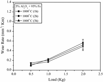
Wear rate versus load for specimens sintered at 1000 °C [21]
-
(2)
In Fe-10% Al2O3 nanocomposite specimens, it was revealed that the amount of iron aluminate phase has increased as compared to that of 5% Al2O3 reinforcement. It was found that in the present case that the wear mechanism maps are generated due to the microploughing effect.
-
(3)
In cobalt oxide doped Fe-10% Al2O3 nanocomposite specimen, it was found that there is a reduction in the iron aluminate phase. Figure 2.8 shows the wear rate versus load plot for specimen (a) 10AFe0.5Co1100(1), (b) 10AFe1.0Co1100(1), and (c) Pure Fe + 0.5% CoO. Adhesive wear takes place at lower loads, whereas abrasive wear dominates at higher loads. For the 0.5% doped Cobalt oxide specimen [10AFe0.5Co1100(1)] up to a load of 1.5 kg, the adhesive wear occurred, but at 2.0 kg, load the wear behavior was abrasive in nature.
Fig. 2.8 
Wear rate versus load plot for specimen a 10AFe0.5Co1100(1) b 10AFe1.0Co1100(1) and c pure Fe+0.5% CoO [22]


On the other hand, 1.0% cobalt oxide doped specimen [10AFe1.0Co1100(1)] showed the abrasive wear under all loads. This may also be reason for failure of the specimen during wear test at 2.0 kg load. Pure iron specimen doped with 0.5% cobalt oxide shows the highest amount of wear [22].
References
P. Sahoo, Engineering Tribology (PHI Learning Private Limited, New Delhi, 2005)
C.W. Bunn, E.R. Howells, Structures of molecules and crystals of fluorocarbons. Nature 174, 549–551 (1954)
M.M. Khruschov, Principles of abrasive wear. Wear 28(1), 69–88 (1974)
C.M. Pooley, D. Tabor, Friction and molecular structure: the behaviour of some thermoplastics. Proc. Roy. Soc. London. Ser. A 329, 251–274 (1972)
K.J. Stout, T.G. King, D.J. Whitehouse, Analytical techniques in surface topography and their application to a running in experiment. Wear 43, 99–115 (1977)
N.P. Suh, Tribophysics (Prentice-Hall Inc., Englewood Cliffs, 1986)
A.F. Offringa, Thermoplastic composites—rapid processing applications. Comp. Part A: App. Sci. Manuf. 27(4), 329–336 (1996)
N.S. McIntyre, D.G. Zetaruk, D. Owen, XPS study of initial growth of oxide film on Inconel 600 alloy. App. Surf. Sci. 2, 55–73 (1978)
K. Endo, H. Goto, Effects of environment on fretting fatigue. Wear 48, 347–367 (1978)
P. Gupta, D. Kumar, M.A. Quraishi, O. Parkash, Corrosion behavior of Al2O3 reinforced Fe metal matrix nanocomposites produced by powder metallurgy technique. Adv. Sci. Engg. Med. 5(4), 366–370 (2013)
P. Gupta, D. Kumar, O. Parkash, A.K. Jha, Structural and mechanical behavior of 5% Al2O3 reinforced Fe metal matrix composites (MMC) produced by powder metallurgy (P/M) route. Bull. Mater. Sci. 36(5), 859–868 (2013)
P. Gupta, D. Kumar, M.A. Quraishi, O. Parkash, Effect of cobalt oxide doping on the corrosion behavior of iron-alumina metal matrix nanocomposites. Adv. Sci. Engg. Med. 5(12), 1279–1291 (2013)
R. Roy, R.A. Roy, D.M. Roy, Alternative perspectives on “quasi-crystallinity”: non-uniformity and nanocomposites. Mater. Lett. 4(8–9), 323–328 (1986)
J.F. Archard, Contact and rubbing of flat surfaces. J. Appl. Phys. 24, 981–988 (1953)
S.C. Lim, M.F. Ashby, Wear-mechanism maps. Acta Metall. 35(1), 1–24 (1987)
H. Ishigaki, I. Kawaguchi, M. Isawa, Y. Toiba, in Wear of Materials, ed. by K.C. Ludema (Springer, New York, 1985)
I. Dinaharan, N. Murugan, Dry sliding wear behavior of AA6061/ZrB2 in-situ composite. Trans. Nonferrous Met. Soc. China 22, 810–818 (2012)
P. Gupta, D. Kumar, M.A. Quraishi, O. Parkash, Influence of processing parameters on corrosion behavior of metal matrix nanocomposites. J. Mater. Env. Sci. 7(7), 2505–2512 (2016)
P. Garg, P. Gupta, D. Kumar, O. Parkash, Structural and mechanical properties of graphene reinforced aluminum matrix composites. J. Mater. Env. Sci. 7(5), 1461–1473 (2016)
P. Jha, P. Gupta, D. Kumar, O. Parkash, Synthesis and characterization of Fe-ZrO2 metal matrix composites. J Comp Mater 48(17), 2107–2115 (2014)
P. Gupta, D. Kumar, O. Parkash, A.K. Jha, Effect of sintering on wear characteristics of Fe-Al2O3 metal matrix composites. Proc. Inst. Mech. Eng. Part J: J. Engg. Tribol. 228(3), 362–368 (2014)
P. Gupta, D. Kumar, O. Parkash, A.K. Jha, Hardness and wear behavior of CoO doped Fe-Al2O3 metal matrix composite (MMC) synthesized via powder metallurgy (P/M) technique. J. Adv. Mater. Res. 585, 584–589 (2012)
Author information
Authors and Affiliations
Corresponding author
Editor information
Editors and Affiliations
Rights and permissions
Copyright information
© 2017 Springer Nature Singapore Pte Ltd.
About this chapter
Cite this chapter
Choudhury, Y., Gupta, P. (2017). Wear Behavior of Composites and Nanocomposites: A New Approach. In: Khan, Z. (eds) Recent Trends in Nanomaterials. Advanced Structured Materials, vol 83. Springer, Singapore. https://doi.org/10.1007/978-981-10-3842-6_2
Download citation
DOI: https://doi.org/10.1007/978-981-10-3842-6_2
Published:
Publisher Name: Springer, Singapore
Print ISBN: 978-981-10-3841-9
Online ISBN: 978-981-10-3842-6
eBook Packages: Chemistry and Materials ScienceChemistry and Material Science (R0)