
Abstract
The spherical head supporting part is an essential part which connects the shell of one kind of front drive axle body, wheel driving and steering, braking structure and other key parts of the body, and to assume the function of load-bearing, steering, driving, braking and so on, it also has an important implications on the load-bearing capacity, steering capability, reliability, service life and safety of the front drive axle. This article mainly introduce the manufacture of the spherical head supporting part which the both ends are thick while the middle part is thin, inside the part is empty, both the inner and outer part are spherical and has special structures. Mainly introduce the technology of dual spherical head forging, hard turning, trundle processing that are used in the manufacture of this spherical head supporting part. Overcome the challenge of dual spherical head forging technology, both ends with reverse fillet shaft induction hardening surface manufacture technology. Smoothly finished debugging and manufacturing the spherical head supporting part. Also finished the test of the front drive axle. The spherical head supporting part’s function, strength, stiffness, reliability, fully meet the requirements of bench test, reliable, and fully meet the demand of the vehicle matching.
Access provided by CONRICYT-eBooks. Download conference paper PDF
Keywords
- The spherical head supporting part
- Dual spherical head forging technology
- Hard turning
- Trundle processing technology
47.1 Analysis of the Spherical Head Supporting Part
The spherical head supporting part is a key part of the front drive axle. By connecting the shell of the front drive axle body and wheel driving and steering, braking structure etc., to undertake the following functions (see Figs. 47.1 and 47.2):

Front drive axle assembly

The wheel part structure
-
1.
Load-bearing function; After welding with the shell of front drive axle body, load-bearing the mass of truck frame and other assembly parts on it;
-
2.
Steering function; Through cooperating with the shell of steering knuckle and other steering knuckle part, realize the steering function;
-
3.
Force transmitting function; Through cooperating with the steering knuckle shell, wheel hub, brake drum, and other component of the matching, undertake the transmission of front axle’s driving and braking force;
In order to ensure the function, performance and reliability requirements of the front drive axle. The spherical head supporting part has the following characteristics (see Fig. 47.3):

The front drive axle and the spherical head supporting assembly
-
(1)
The spherical head supporting part has hollow structure;
Driving shaft that passes through the inner hole connects half axle gear and the driving wheel, realize the driving function;
-
(2)
Both ends are thick while the middle part is thin; In order to ensure the front drive axle assembly’s welding strength, improve the bending strength, stiffness and reliability of the front drive axle assembly, the diameter of the right guiding and location restricting cylindrical surface and welding part’s cylindrical surface is large. In order to avoid turning interference and ensure the front drive axle assembly’s steering angle, the diameter in the middle part is small. Because the requirements of steering, braking functional, the diameter in left is large;
-
(3)
Both the inner and outer surface in the left part are spherical structure.
The ball cage cardan joint is install in the inside spherical, so it can turn freely; The outside spherical surface cooperate with the oil seal of the ball cage cardan joint, to reach the role of dustproof and seal;
The difficulty in manufacturing the spherical head supporting part (see Fig. 47.4):

The spherical head supporting part
-
(1)
Forging
The material of the spherical head supporting part is 40Cr, in order to ensure the strength, stiffness and reliability, the workblank must adopt forging forming process, so as to ensure the quality of metal streamline, avoid stress concentration. Both the inner and outer surface in the left part are spherical structure, and the sphere surface is more than half a sphere, it will be very hard to put out of the forging’s inside spherical surface if adopt normal forging process.
-
(2)
The manufacture of axis neck
As a part relating to the safety, the strength, stiffness and reliability directly affect the safety of driving personnel. The middle axis neck is the weakest link, excircle diameter is Ф72 mm, thickness is 16 mm, this part demands induction hardening, the surface hardness is (52–58) HRC, in order to avoid stress concentration, the surface roughness of axis neck surface and the transition fillet between axis neck and both ends must not higher than Ra0.8. Because the hardness of processing site is very high, it can only use grinding processing by normal manufacturing technology, but it’s hard to ensure both of the transition fillets transite smoothly by grinding.
47.2 Analysis of Manufacturing Technology for the Spherical Head Supporting Part
47.2.1 Analysis of the Forming of the Spherical Head Supporting Part’s Workblank
Because both the inner and outer surface of the part are spherical structure, the difficulty is in the forging of the inside spherical surface. By decomposing the forming of the dual spherical structure in two steps to complete forging the dual spherical structure. (1) To forge the right half sphere, leaving forging allowance for the left half sphere, and forge to annular cylindrical column; (2) To forge the left half sphere by necking down, avoid the problem of putting out of the forging workblank (Fig. 47.5);

Forging process drawing
Forging process
Blanking → induction heating → moulding (I forge) → trimming, chamfer → normalizing → cleaning → necking down (II forge) → thermal refining → surface cleaning → examine → rust-proof.
-
(1)
Design the forging workblank drawing
According to the structure of spherical head supporting part and forging process’s characteristic, confirm the workblank’s machining allowance, forging slope, fillet radius and the tolerance of the workblank (Fig. 47.6).

The forging workblank drawing
-
(2)
Choicing of the forging equipment
The forging of the spherical head supporting part has follow characteristics: the part has big forging deformation, need to forge repeatedly; Considering the forging process’s characteristic and forging equipment resources, select the electric screw press as forging equipment (Fig. 47.7).

Electric screw press
The characteristics of electric screw press:
-
(1)
Electric motor directly drive the flywheel, simple construction, strike energy control accurately, high molding precision.
-
(2)
Can provide large forging energy.
-
(3)
Can adjust stroke height, no bottom dead point, don’t need to adjust the mould height, won’t jammed; Can forging workpiece according to setting load, to forging and forming through multiple strikes.
-
(3)
The choice of equipment nominal pressure
Electric screw press’s nominal pressure is half of its maximum force.
Electric screw press’s specification can be selected according to the conversion method:
In this formula:
- P:
-
Electric screw press’s nominal pressure (kN);
- G:
-
Tonnage of forging hammer calculated based on hammer forging (t)
Tonnage of forging hammer calculated.
Tonnage of forging hammer refers to the quality of forging hammer falling part, with tons of units.
According to the empirical formula:
Tonnage of forging hammer \( G = (4\sim 6) \times F/1000({\text{t}}) \)
In this Formula:
- F:
-
projection area of forgings \( \left( {{\text{cm}}^{ 2} } \right) \)
Calculation predicts:
-
(4)
Workblank calculate
Common forging can be divided into mushrooming deformation forgings, long pole type forgings, head hammering forgings three types. According to the characteristics of the spherical head supporting part structure, it can be calculated as the type of head hammering forgings.
Head hammering forgings generally select workblank diameter according to indeformable pole diameter, then calculate mushrooming deformation forging head volume \( V_{\text{head}} \), trimming volume \( V_{\text{trim}} \), indeformable pole volume \( V_{\text{pole}} \), the blank volume (see Figs. 47.8 and 47.9):

\( V_{\text{head}} \)

\( V_{\text{pole}} \)
In this formula: δ—loss on heating rate, induction heating select δ = 0.5–1%.
pole diameter Ф110 mm;
Blanking length:
-
(5)
Moulding forming
The spherical head supporting part’s forming mould is made up of moulding forming and necking down mould (see Figs. 47.10 and 47.11).

Forming mould

Necking down mould
47.2.2 The Spherical Head Supporting Part’s Middle Axis Neck Machining Process Plans
When the spherical head supporting part is in the process of practical work time, middle axis neck bear alternating bend torsion load, impact load caused by uneven road, braking, etc. Use under harsh conditions, therefore the middle axis neck’s surface roughness, residual stress, hardness and so on are very strict. In the middle of axis neck \( \phi 72_{ - 0.05}^{0} \) surface roughness is Ra0.8, the transition fillet surface both sides R10, R20 surface roughness is Ra0.8, the middle of axis neck and both sides transition fillet need induction hardening, and it can’t have tool marks connection and other tool marks which may cause stress concentration in both of he transition fillet surface.
According to the requirements of parts, adopt the processing technology of hard cutting and trundle processing to trial-manufacture.
-
(1)
Hard cutting technology
Hard cutting technology (by turning instead of grinding), means considering the turning of the strain hardening steel as final processing or fashioning, to replace the common grinding technology. it’s machining accuracy can get up to IT5, surface roughness Ra ≤ 0.6 μm, circular degree 0.005 mm.
The general range of hard cutting is 45–65 HRC, hardness of 45 HRC is the start point of hard cutting, but it usually used on the workpiece above 55 HRC. The hardness of axis neck in the middle of spherical head supporting part is (52–58) HRC, so is suitable for hard cutting (see Fig. 47.12).

Axis neck hardness
-
1.
The choice of the blade
CBN blade is most suitable for hard cutting, can provide security blade abrasion rate in the process of continuous cutting. So we choice the CBN blade.
-
2.
Cutting dosage and cutting conditions
The suitable cutting speed’s range of hard cutting is 50–200 m/min, commonly used range is 100–150 m/min, the hardness of workpiece material is higher, its cutting speed should be smaller. Normal cutting depth is 0.1–0.3 mm, when require high surface roughness, it should choice small cutting depth. Normally choice feed speed 0.025–0.25 mm/r.
-
(2)
Trundle processing
It is a kind of pressure forming processing for trundle processing. It is the use of plastic deformation characteristics of the metal in the normal temperature. The surface metal of the workpiece produces plastic flow to the original residual dips in the trough, which is pressed by the trundle tool. The purpose is to reduce the workpiece surface roughness value. It happened cold hardening, the density of fiber and residual stress layer of the surface organization. Thereby, it is improve to abrasion resistance, corrosion resistance and coordination of the workpiece surface. The value of the surface roughness will be less than 0.08 um, meanwhile it will be improve the hardness 15–30% and abrasion resistance 30% by pressing the surface of the workpiece.
The process parameters of trundle processing:
-
1.
Roller pressure
Rolling pressure whether it is right choice, is very important to roughness, size and accuracy after rolling the surface. The surface roughness increase with the rolling pressure increases in general. But, as the rolling pressure cross the certain value, the surface roughness don’t increase. If rolling pressure continues to increase, the surface of the part would be to deteriorate, appear crack even.
-
2.
The feed rate is determined by the diameter of the trundle. The smaller the feed, the less the surface roughness. The best feed rate should be determine by test.
-
3.
It is important to the surface roughness and geometry for interference when rolling. The most reasonable interference is 0.027–0.036 mm through experiment, the surface roughness is the minimum now. The most reasonable interference should be determined by many experiments according to the specific conditions.
-
4.
It is not important to the surface roughness for rolling velocity, then we can improve production efficiency by improving the speed of rolling.
-
5.
The times of rolling shoulds not be too much. It is the most significant effect to roller once, which can reduce the roughness 2–3 grade. The more times, the less effect.
-
6.
The trundle processing is to use trundle rolling method, thus the diameter of the workpiece will be changed before and after the processing (inner diameter will expand, outer diameter will reduce). It should consider the change before the last process in order to be processed to dimensional tolerance range diameter variation is related material, hardness of the workpiece and rolling, so it should be determine after trying processing 2–3 times for the initial size (Figs. 47.13 and 47.14).
Fig. 47.13 
The trundle tool
Fig. 47.14 
The trundle


47.3 The Manufacturing Process of Spherical Head Supporting Part
Manufacturing process plans: NC rough turning → NC precision turning → surface induction hardening → boring internal hole → hard turning excircle → surface rolling → milling the end face of spherical head → rolling main pin hole, milling end face, chamfer (see Fig. 47.15).

Technology diagram
-
(1)
NC rough turning
-
(1)
Clamping spherical surface and limiting the left end face, rough turning all the excircle surface in the right, turning right end face and taper hole to it’s size.
-
(2)
Clamping right turned excircle surface and limiting the right end face, rough turning left excircle surface, turning inner spherical and inner hole in the middle of axis neck (see Fig. 47.16);
Fig. 47.16 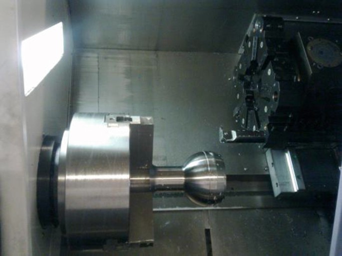
NC rough turning

-
(2)
NC precision turning
In order to ensure the shape and position accuracy of the spherical head supporting part. Adopt special turning tooling, use the inner hole Ф42JS8 installing lining and oil seal hole Ф54H8 limit the workpiece, NC turning the whole excircle surface at one time, so can reduce limiting and clamping, ensure the coaxiality between excircle and inner hole, and ensure the positional accuracy between each cylindrical.
-
(1)
Using the mandrel limit, precision turning all the excircle, keep machining allowance for induction heating, each side keep 0.3 mm (see Fig. 47.17);
Fig. 47.17 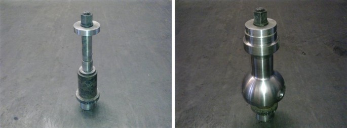
NC precision turning mandrel
-
(3)
Heat treatment-surface induction heating

To ensure the follow content by design and manufacture special open induction coil to heat the middle of axis neck (see Fig. 47.18).

Induction hardening
-
(1)
Have equal depth of effective hardened layer in the middle.
-
(2)
The depth of effective hardened layer transit gradiently both in the middle of axis neck and two transition fillets beside.
-
(4)
Boring internal hole
Use the right excircle and end face to limit the workpiece, boring hole Ф42JS8 installing lining and oil seal hole Ф54H8.
-
(5)
NC hard turning excircle
Use the precision turning mandrel to locate, precision turning all excircle to drawing size, keep 0.004–0.006 mm rolling allowance in middle axis neck.
-
(6)
Surface rolling
Rolling the middle axis neck and two transition fillets beside.
-
(7)
Milling spherical head end face-vertical machining center
Use the right excircle surface and end face to locate, milling spherical head end face.
-
(8)
Horizontal machining centre
Use the right excircle surface and end face to locate, drilling, boring the main pin hole, milling the end face, chamfer (see Fig. 47.19).

The spherical head supporting finished part
47.4 The Test Results and Conclusions of Spherical Head Supporting Part
-
(1)
The vertical bending and stiffness test of the shell of front drive axle (see Fig. 47.20)
Fig. 47.20 
The result of vertical bending and stiffness test of the shell of front drive axle

The load and deformation curve at triple load
-
(2)
The test of vertical bending fatigue life of front drive axle (see Figs. 47.21 and 47.22)
Fig. 47.21 
The result of vertical bending fatigue life test of front drive axle
Fig. 47.22 
The broken sample of A1


Note: A2 sample’s fatigue life reach up to 635,000 times, the sample is still didn’t break and the test was stop.
By installing in the front drive axle and bench testing, the spherical head supporting part’s function, strength, stiffness of supporting structure, reliability, fully meet the requirements of bench test, high safety coefficient, reliable, and fully meet the demand of the vehicle matching.
-
(3)
Conclusion
Through the trial-manufacturing of the spherical head supporting part, verified the machining processability, and provide reference for the quantity production. Increase awareness of special structure part’s forging, hard turning and trundle processing. Gather experience for both choicing machining tools and selecting cutting parameters of hard turning and trundle processing.
References
Liu J (2011) Car parts forging technology. Beijing Institute of Technology, Beijing, pp 8–23
Sun F (2006) MINFRE. In Machining technology, vol 2. China Machine Press, Beijing, 12 (Chapter 1, p. 88, Chapter 10, p. 55)
Author information
Authors and Affiliations
Corresponding author
Editor information
Editors and Affiliations
Rights and permissions
Copyright information
© 2017 Springer Nature Singapore Pte Ltd.
About this paper
Cite this paper
Zhao, S., Zhai, L., Song, B., Cui, K., Li, Y., Yu, B. (2017). Analysis of Manufacturing Technology for the Spherical Head Supporting Part. In: Proceedings of SAE-China Congress 2016: Selected Papers. SAE-China 2016. Lecture Notes in Electrical Engineering, vol 418. Springer, Singapore. https://doi.org/10.1007/978-981-10-3527-2_47
Download citation
DOI: https://doi.org/10.1007/978-981-10-3527-2_47
Published:
Publisher Name: Springer, Singapore
Print ISBN: 978-981-10-3526-5
Online ISBN: 978-981-10-3527-2
eBook Packages: EngineeringEngineering (R0)