
Abstract
In recent decades, the number of robotic standards has increased, and this progress has encouraged the integration of service robots and growth in the number of robotic devices with various communication protocols used in the smart home. In this chapter, we study different standards that could be used for the integration of mobile robots and unmanned vehicles in the digital home. As will be seen, the origins of these standards are twofold. On the one hand, standards have been developed in a military context such as JAUS or 4D/RCS, which is logical given that the control and coordination of autonomous vehicles has many potential applications in this field. On the other hand, standards have been developed in a computer science context, where interoperability between the different agents that may interact in a networked environment is a major problem.
Access provided by Autonomous University of Puebla. Download chapter PDF
Keywords
These keywords were added by machine and not by the authors. This process is experimental and the keywords may be updated as the learning algorithm improves.
4.1 Introduction
During the early years of computing science, only large organizations such as NASA or the US government could afford to have computers. At that time, no one would have ever imagined the astonishing evolution of computers together with the continuous price drop in consumer electronics. Nowadays, there is at least one computer in almost every home in developed countries, with enough computational power to ridicule the first computer systems. Advances due to the evolution of computers are the first breakthrough in the field of the digital home.
The next revolution in the smart home is expected to come from the world of robotics. At present, the use of robotics is limited to industrial areas, although service robots that assist us in routine tasks such as cleaning the house, mowing the lawn or even preparing meals are becoming common. Nevertheless, different problems have to be solved before service robots become as popular as computers. In particular, interoperability between the different systems that may exist in future homes is an ongoing issue.
The idea that the reader must have in mind during this chapter is interoperability. Interoperability is the key component to solving the smart home jigsaw puzzle. Thus, in this chapter, we will place special emphasis on the interoperability aspects of the different standards. In addition, different research projects on the interoperability and control of robotic systems and unmanned vehicles will be surveyed. Behind all these standards and projects, there are stories of success and failure, and many valuable lessons about the complex world of interoperability. At this point, it is difficult to know if any of these alternatives will prevail and become a consolidated standard for the integration of robots in the digital home. However, what we know for sure is that any succeeding standard will have learnt from all that will be presented here.
4.2 Military Standards
4.2.1 Joint Architecture for Unmanned Systems (JAUS)
The JAUS standard was developed for the US Defense Department (English 2007) by the JAUS Work Group, which is composed of research groups from the government (US Army ARMDEC), industry (SSC San Diego, WINTEC Inc., iRobot) and academia (Virginia Tech, University of Florida). JAUS was defined as an open and scalable standard that would meet the needs related to the communication of unmanned systems regardless of the platform used. The development of JAUS has tried to meet the following six goals (Wade 2006):
-
1.
Independence of the vehicle’s platform;
-
2.
Isolation of the mission;
-
3.
Hardware independence;
-
4.
Independence from the technology;
-
5.
Independence from the operation; and
-
6.
Independence from the connection used.
The JAUS architecture is composed of three levels:
-
Level 1 – Inter subsystem: The purpose of this level is to support interoperability between subsystems. It is responsible for specifying requirements between the subsystems (Robot to Robot, Robot to Controller, Controller to Controller).
-
Level 2 – Inter nodal: The purpose of this level is to support the interoperability between nodes. To this end, it specifies requirements between the subsystems (interoperability between data loads or between the on-board control and data loads).
-
Level 3 – Inter components: The purpose of this level is to provide a reusable software source. It specifies requirements for each component (component by component, such as sensors and motors).
In 2004, a process of transition from the JAUS Work Group to the Society of Automotive Engineers (SAE 2010) started. This developed the standard through the AS-4 (Technical Committee on Unmanned Systems) (SAE 2006). The following norms migrated from JAUS to a framework based on the following services:
-
JAUS Transport Standard, AS5669 (SAE-TS 2009). This is in charge of defining the creation of packets with the destination and source addresses and TCP and IP headers and links.
-
JAUS Core Service Set, AS5710 (SAE-CSS 2010). This is responsible for providing the means for the software entities in an unmanned system to communicate and coordinate among their activities.
-
JAUS Mobility Service Set, AS6009 (SAE-MSS 2009). This is in charge of making the migration from the first drivers to the new development platform of the AS-4.
Today, the main application of JAUS is focused on the use of unmanned civilian and military vehicles.
4.2.1.1 Application of Military Unmanned Vehicles
A major center for development of military unmanned vehicles exists at the SPAWAR Systems Center (SSC) in San Diego (California). There, a JAUS work team focuses on the development of surveillance systems, such as MDARS (Mobile Detection Assessment Response System), which are used in autonomous vehicles for military bases with restricted access.
The US Defense Department uses MDARS to meet security and surveillance needs in hostile environments for humans. In this way, it provides an integrated solution, where unit patrol vehicles are controlled just by a single control operator. Moreover, SSC has developed a distributed processing system called Multiple Resource Host Architecture (Everett et al. 2000) which, along with MDARS, was tested by the JAUS work team in December 2003 to demonstrate the level of interoperability between control operator units (COUs) and unmanned systems (Nguyen 2005). In this experiment, COUs were equipped with a screen capable of displaying the statuses of each patrol vehicle, and thereby they controlled each one of the unmanned systems (Carroll et al. 2004).
These experiments show how the JAUS architecture provides interoperability for the remote control of unmanned systems while fulfilling the objectives mentioned in the general characteristics section.
4.2.1.2 Application of Civil Unmanned Vehicles
In 2004, Virginia Tech launched a project to implement simultaneously the JAUS standard in the following seven unmanned vehicles:
-
1.
MATILDA
This was the first interoperable vehicle designed by Virginia Tech in 2002. It was designed as an evaluation, development and demonstration platform of the JAUS standard. It had to fulfill some functional requirements:
-
It had to be teleoperable through a COU;
-
It had to be capable of driving autonomously via GPS commanded by a COU;
-
It had to interact with other subsystems of JAUS (either vehicle or COU);
-
It had to accept JAUS workloads from other devices;
-
It had to allow an easy modification and/or addition of intelligent software; and
-
It had to ease the demonstration, evaluation and testing of the JAUS standard.
-
-
2.
JOHNNY-5
This was developed in 2004 to participate in the AUVSI Intelligent Ground Vehicle Competition in 2005. Owing to its robustness and its capability to navigate via GPS, it quickly replaced MATILDA. The main problems of this model were the failures in the camera interface and the starting force on the wheels.
-
3.
CADILLAC SRX
Grant Gothing and Jesse Hurdus, researchers from Virginia Tech, managed to implement the JAUS standard on the Cadillac SRX, creating the first luxury unmanned vehicle in the world (Gothing and Hurdus 2006). The challenge of this model depended on development of a JAUS-based vehicle able to use potential field methods (Koren and Borenstein 1991) for navigation. The result was the creation of a software topology, based on operational subsystems, nodes and components (see Fig. 4.1).
Fig. 4.1 
JAUS topology (University of Seville 2010)
However, when they launched this vehicle in the Blind Driver competition (Blind Driver Challenge 2010) they detected some issues that could be improved (Faruque 2006). For example, every driver had to know the turn angle of the vehicle and, according to the control messages of the JAUS specification, only one controller per component was allowed.
-
4.
GEMINI
Gemini was developed as an extension of Johnny-5. The idea was to create an articulated robot with four wheels. It won the JAUS Award at the AUVSI Intelligent Ground Vehicle Competition in 2006 because of its refined design, the long life of its batteries (5 h), its innovative mobility and the ability to deal with bigger workloads under the JAUS architecture.
-
5.
HELIUM RED (Unmanned Ground Vehicle; UGV) and THE RMAX (UAV)
HeLiUm RED (HElicopter LIfted UnManned Reconnaissance and Exploration Drone) redefines the traditional notion of collaboration between UAVs and UGVs (RMAX-HELIUM THE RED). This small unmanned vehicle is light enough to be carried by the VT Yamaha RMAX UAV. Initially, the JAUS standard was implemented to simplify communication with the vehicle; however, vehicles are usually treated as subsystems of the JAUS architecture, but in the project HELIUM RED, the UGV operates as a single node.
-
6.
ROCKY
This is another example of the vehicles used by Virginia Tech in the DARPA Grand Challenge. The JAUS implementation in Rocky has taken place in two stages:
-
Teleoperability: Through the primitive driver, they could make sure that the vehicle was teleoperated making use of the COU, but nowadays with the use of Global Position/Speed Sensors, the COU, speed and position can be kept on track and transmitted through a connection service.
-
Portability of the basic code from Cadillac SRX directly to Rocky. This feature can be seen as a demonstration of the reusability existing when developing autonomous vehicles under the JAUS architecture.
Owing to these achievements, Virginia Tech established, as functional requirements, that their prototypes had to be interoperable with other JAUS subsystems (applied to both COUs and vehicles). Throughout this research, they realized the need to integrate some specifications in the JAUS Service Specification standard that would make use of messages in charge of waiting for a response that will allow the COU and the vehicles to make behavior decisions for a better interaction between them.
With respect to the development of unmanned vehicles, the company TORC started the ByWire XGV Project (TORC 2010). This project is being developed over a Ford Escape Hybrid using the JAUS standard as a platform to interact with the different parts of the car (steering, throttle, brakes and gear system). The vehicle has an Ethernet interface installed in a central console that allows for remote control of the vehicle by a COU, making use of the SAE AS-4 (JAUS) architecture. The use of the JAUS standard makes sure that ByWire XGV is compatible with any other platform developed on JAUS. It is important to note that the ByWire XGV has maintained speeds of 160 km/h. The DARPA Urban Challenge (DARPA 2007) checks the utility of unmanned vehicles in traffic environments and assesses how they stick to conventional rules of the road. This is a challenge for participants to ensure that unmanned vehicles can perform complex movements such as parking or taking navigational decisions at intersections. In 2005, the DARPA Grand Challenge competition, the University of Florida and Virginia Tech competed with their unmanned vehicle projects based on JAUS.
Applied Research Inc., Virginia Tech, University of Florida, iRobot and the US Air Force Research Lab showed the importance of interoperability in robotics in an experiment (Clark 2005a, b). To this end, each consortium member made their COU able to interact with all robots and control all loads. The benefits of the JAUS standard were successfully proven after showing the independence of the technology used in unmanned vehicles and robots.
Baity (2005), talking about the future of JAUS, mentions the need to focus on development of software. This author says that it is a primary point to take into account to minimize problems in the progress of UGVs.
-

4.2.2 Other Military Standards
4.2.2.1 4D/RCS (Real-Time Control Systems)
The 4D/RCS architecture provides a reference model for military unmanned vehicles. 4D/RCS is a method of designing, integrating and testing intelligent systems software for vehicles that have a certain degree of autonomy (Albus et al. 2002a). It is an autonomous intelligent control system architecture for vehicles that can be either teleoperated or fully autonomous.
4D/RCS (Kim et al. 2002) specifies the way in which software components are distributed and interconnected, and that is the reason why it became a model for military unmanned vehicles. The importance of this standard lies in the way in which unmanned vehicles must manage situations in hostile environments to complete their missions. As a result of the above features, the 4D/RCS fulfills perfectly the specific needs of the Department of Defense and US Army standards (Albus et al. 2002 b).
4D/RCS architecture was based on the assumption that different knowledge representation techniques may offer greater advantages. The aim was to cover all of them to create a real-time control system for objects that move in the real world (Schlenoff et al. 2006).
The Demo III UGB Program (Shoemaker and Bornstein 1998) developed and demonstrated advances in control of unmanned systems, especially small UGVs under supervised control. That is where the 4D/RCS architecture and its characteristics arose. This protocol allows intelligent vehicles to adapt to a changing world, to extract deeper information from a dynamic world and to merge such information with previously available information to improve a vehicle’s performance.
The intelligent control of a 4D/RCS system is based on three layers of abstraction:
-
A conceptual framework. This is the highest layer of abstraction and covers the full range of operations that involve intelligent vehicles, from a simple actuator for some milliseconds to lots of vehicles during long periods of time.
-
A reference model architecture. This defines a hierarchical control structure and at each level functional processes are included.
-
Engineering guidelines. These are the lowest layer of abstraction in intelligent control. They define how to design intelligent vehicles to work in groups with other intelligent vehicles.
4.2.2.2 NATO STANAG 4586
In 1998, a NATO expert team, composed of members of government and industry (CDL Systems 2010), started working on the development of the standard STANAG 4586 (Compliant Ground Control System for UAV) (Defense Update 2007), which was ratified by NATO in 2002 for the communication and interoperability of its UAV.
The search for interoperability between unmanned systems is essential when meeting objectives in military terms. The line of development should be focused on interoperability between land systems, aerial systems and elements of control, command, communication, computer and intelligence (C4I) (STANAG 2004).
STANAG 4586 was developed as an interface control definition capable of defining a common number of data packets for two new interfaces (CDL Systems 2010):
-
A data link interface among ground control stations and aerial vehicles; and
-
A command and control interface among ground control stations and C4I systems.
According to Cummings et al. (2006), STANAG 4586 is the only standard that promotes interoperability in control networks of UAVs. There are five interoperability levels defined in this standard (Defense Update 2007):
-
Level 1: Reception/transmission of data packets related to UAV.
-
Level 2: Received live data about intelligence, surveillance and reconnaissance.
-
Level 3: Control and monitoring of data packets of UAVs in addition to the reception of intelligence, surveillance and reconnaissance and other data.
-
Level 4: Control and monitoring of UAV, except from launch and recovery.
-
Level 5: Control and monitoring of UAV including launch and recovery.
STANAG 4586 supports Electro-Optical/Infrared, Synthetic Aperture Radar, communication transmission and data link interface resources.
4.3 Computer Science Standards
4.3.1 CORBA
CORBA is a standard that provides a platform for the development of distributed systems. It allows an easy RMI under an object-oriented paradigm. CORBA is defined by the Object Management Group (OMG), which defines APIs, communication protocols and all necessary items to ensure interoperability between different applications running on different platforms. CORBA uses an IDL to specify the interfaces through their functionality. This is a way to indicate how CORBA data types must be used in implementations of client and server.
All this means that CORBA is a kind of middleware (platform of distributed services, independent of the operating system) that guarantees success in the transit of data across different platforms and applications. It is applied in RTS and is efficient enough for any kind of problem. The main features of this standard are:
-
It is a distributed object standard.
-
It specifies the architecture the system should have, is flexible and heterogeneous.
-
Interoperability.
-
Scalability.
-
Transparency, facilitating client–object communication (Vinoski 1997).
-
Naming service.
-
It sets a minimum object model.
-
Each object implements an interface.
-
The definition of interfaces is made through the IDL, making it independent of the programming language.
-
The reuse in software is achieved through interface inheritance.
-
Multiple inheritance.
-
The details of an object’s implementation cannot be accessed.
-
4.3.1.1 Components
-
The Object Request Broker (ORB) is the CORBA object manager and is part of its core. It allows for the invocation of static and dynamic objects. It can operate without the services and facilities provided by CORBA. It handles the invocation and search for remote objects using dynamic methods for the invocation. It is responsible for giving back the object attributes of the object accessed through the IDL of the object (Vinoski 1997). Locally, it also collects information on the objects to pass to other ORBs and handles local computer security (Fig. 4.2).
Fig. 4.2 
CORBA architecture (University of Seville 2010)
-
IDL, Language for defining interfaces. Since it is a declarative language and not a programming language, it defines interfaces independent of the implementations of objects.
-
Dynamic Invocation Interface (DII). Generic Stub. Client side.
-
Dynamic Skeleton Interface (DSI). Generic skeleton. Server Side.
-
Both DII and DSI are based on the interface repository, which is a CORBA object that contains information on the object’s interfaces and their types. It allows applications to access this information in a static or a dynamic way. The main advantage is the support given to the dynamic calls.
-
The implementation repository is required when the objects are persistent. Most general purpose ORBs provide a repository of implementations that supports indirect connections for persistent references. This characteristic solves the problem of direct connections for persistent references. It has also a bad point; it slightly reduces the good working of the first invocation from client to server. It also offers various modes for the automatic activation of server objects (Henning and Vinoski 1999).
-
The object adapter is the bridge between the ORB and CORBA object implementations. This allows it to make requests to an object without knowing its interface, since the object adapter adapts the object’s interface to that expected from the object making the request.
-
Communication protocols between ORBs. CORBA is based on the protocols GIOP (General Inter-ORB Protocol) and the standard protocol IIOP (Internet Inter-ORB Protocol). GIOP specifies the types of messages and the format to transport requests between ORBs. IIOP specifies the way TCP/IP is implemented over GIOP. Thanks to these protocols, ORB can be integrated even if it comes from different developers.

4.3.1.2 Services
There is a large set of standard services offered by CORBA (OMG 1998). These services are added to the ORB interface to complete it; however, they are optional. The most important include:
-
Concurrency Service. Mediates concurrent access to an object such that the consistency of the object is not compromised when accessed by concurrently executing processes.
-
Event Service. This defines two roles for objects: the supplier and the consumer. Consumers process information in the events that are produced.
-
Naming Service. This is the main mechanism for objects that will be invoked by most customers from an ORB-based system.
-
Persistent State Service. Replaces the persistent object service. These are interfaces that provide persistent information, namely data objects stored in databases.
-
Property Service. Can attach dynamic properties to objects outside the static IDL-type system.
-
Security Service. The security service of CORBA provides various security policies to cater for different needs that lead to a secure architecture. CORBA’s security can be used in a wide range of systems. It also allows the reuse of its own security protocols. These include:
-
Authentication and identification of objects or users (i.e. verifying that they are who they seem).
-
Access control and authorization.
-
Security audits.
-
Secure communication between objects.
-
Non-repudiation policy
-
The CORBA security service is included in the safety process of OMG. Among the OMG security specifications, we can find:
-
At an API level:
-
ATLAS (Authorization Token Layer Acquisition Service)
-
RAD (Resource Access Decision Facility)
-
-
In CORBA’s infrastructure:
-
CSIv2 (Common Secure Interoperability, version 2)
-
CORBA Security Service
-
-
Time Service. Allows an object to ascertain the time along with an estimated error associated to it.
-
Trading Object Service. Facilitates the search for objects, services, features, functionalities and so on.
4.3.1.3 Application Examples
Some frameworks exploit the features of CORBA for telerobotic systems, whereas some applications may be based on the manipulation of complex systems remotely (Bottazzi et al. 2002).
CORBA is commonly used in telecommunication robots in real time as well as to keep track on them. At the University of Auckland, researchers tested the LEGO Mindstorm and Khepera models to demonstrate the reliability of a design for the distributed control of robots using CORBA (Woo et al. 2003).
The Institute for Computer Design and Fault Tolerance at the University of Karlsruhe in Germany presented a distributed software architecture based on CORBA for the autonomous service robot Albert2. The development was focused on the modularity and integration of learning aspects (Knoop et al. 2004).
The research group there proposed a system for controlling a humanoid robot based on CORBA. Using this architecture in a distributed environment such as a local network, it is possible that various humanoid robots all over the world can share their own modules via the Internet (Takeda et al. 2001).
CORBA has been used to integrate a distributed system of multiple mobile robots in a simulated environment that offers the possibility of a collaborative control (Zhang et al. 2009).
4.3.2 UPnP
UPnP is a set of protocols (Jeronimo and Weast 2003) or an architecture proposed by Microsoft and promulgated by the UPnP Forum (UPnP Forum 2010). The main goals of UPnP are to simplify the implementation of networks at home and in corporate environments and to connect devices automatically to the network without user intervention. UPnP allows devices to connect perfectly and thereby simplifies network implementation at home (e.g. data exchange, communications and entertainment) and in corporate environments. It provides a distributed and open networking architecture based on already existing protocols and specifications, such as UDP, SSDP, SOAP or XML (Bray et al. 2008). In addition, it is supported by IP as illustrated in Fig. 4.3. Owing to its independence from any particular vendor, operating system and programming language, APIs connected to a network are able to control, negotiate and exchange information and data easily and transparently to the user. UPnP is independent of the physical medium, and it can work over phone lines, power lines, the Ethernet, RF, IrDA and IEEE 1394.

UPnP architecture (de la Pinta et al. 2011)
UPnP enhances the concept of a digital home platform in which all household devices should work together. It aims to control each device in the smart home, from consumer electronics to robots, through home appliances using wired or wireless networks. However, up to now, UPnP has not been widely used to manufacture such devices, and it has most commonly been used in simpler systems such as blinds, turning on lights or alarms.
The main feature of this protocol is that there is no need to configure anything when a device is connected to the network. Device services will be automatically available to be used for other entities on the network. This is the main idea in UPnP: each device (a robot, a router, etc.) is available for every entity on a LAN. To offer its services, the device publishes them using a message-passing protocol. UPnP is able to detect when a new device is added to the network. Devices receive an IP address from the network or they assign their own IP (Auto-IP) if a DHCP server does not exist. They then publish this to the network and every device connected to it in order to provide all interesting information such as logic name, developer, model and serial number or the services they offer. This way, the user does not have to worry about complex configurations; he or she just has to add the device to the network.
To understand how UPnP works, we need to describe the components existing on the network and the required stages, including the protocols, to reach interoperability between all UPnP devices.
4.3.2.1 Components
A UPnP network has three main components: devices, services and control points. Components are described below as based on Jeronimo (2004) and the information obtained from Members of the UPnP Forum (2008):
-
1.
Devices
UPnP devices are logical containers for a service or set of services, and sometimes for other devices (embedded devices). Embedded devices can be discovered and used independent of the main container. Each UPnP device may offer any number of services. By itself, a device just provides a self-description of its information in an XML device description file, and a device’s services are those that provide real functionality and execute the actions.
-
2.
Services
Services provide real functionality and can invoke actions. Each service may contain any number of actions. Each action has a name and an optional set of input and output parameters. A service has an identifier (URI) that uniquely identifies it among all of services. It may keep variables that represent the current state of the service. These state variables may trigger events if they are defined as evented.
-
3.
Control points
A control point is a network entity that invokes the functionality of a device. It is capable of discovering and controlling other devices. In client/server terms, the control point will be the client and the server role is assumed by the device. Once the device is found, the control point is capable of:
-
Getting the device description and a list of services.
-
Getting the service’s descriptions.
-
Invoking actions to control the service.
-
Subscribing to the service. When a service’s status changes, the device sends an event to the control points subscribed to the service.
-
4.3.2.2 Protocols
This section provides a brief description of the UPnP protocols (see Fig. 4.3) used in these networks:
-
TCP/IP: This is the connection-oriented communication protocol for the Internet and other similar networks. It is based on the idea of an IP address; in other words, it assigns an IP address to each computer or device connected to the network. TCP/IP provides the basis upon which to build a UPnP network.
-
UDP/IP: This is a connectionless protocol that unlike TCP/IP provides a direct way to send and receive datagrams over an IP network. It supports the HTTPU and HTTPMU protocols described next.
-
HTTP/HTTPU/HTTPMU: These protocols are essential for building UPnP entities. HTTPU and HTTPMU are the unicast and multicast variants of HTTP. These variants are defined to deliver messages on top of UDP/IP; on the contrary, HTTP works over TCP/IP.
-
SSDP: This is a protocol that can search for UPnP devices and announce devices and services. Searches and announces used to be made by sending a multicast SSDP message over HTTPMU; however, this may be sent in a unicast message now. When a device receives a search message, it checks the search criteria and if it matches, it will respond with a unicast SSDP message over HTTPU, using the statement “200 OK,” which indicates that the request was successful. A SSDP packet is just an HTTP message with the statement “NOTIFY” (to announce) or “M-SEARCH” (to search).
-
SOAP: This provides a standard mechanism for packaging messages and it defines how two objects in different processes can communicate by exchanging XML files. Each control request is a SOAP message that contains the action invoked and all requested parameters. The reply is another SOAP message that contains the results of the action or the errors as appropriate.
-
GENA: This defines an HTTP notification architecture that allows transfer notifications between HTTP resources.
-
XML: This organizes, stores and exchanges information, and its main function is to describe data. It is used in UPnP for device and service descriptions, control messages and events.
-
HTML: This is a markup language that uses a set of markup symbols or codes to structure text and multimedia documents and to set up hypertext links between documents.
4.3.2.3 UPnP Operation
To describe the way that the protocol operates, we need to show the six basic steps in a UPnP network: Addressing, Discovery, Description, Control, Eventing and Presentation. Addressing may be considered step zero of UPnP networking. This book presents a simplified version of how UPnP operates. However, these steps are detailed in the UPnP Device Architecture document (Members of the UPnP Forum 2008):
-
1.
Addressing
Devices and control points must obtain an IP address before they can join to a UPnP network; therefore, when they are first connected to the network they must search for a DHCP server to get an IP address or use Auto-IP to obtain an address. UPnP entities may retrieve an IP address from a DHCP server; to that effect, both devices and control points must have a DHCP client. If the network does not have a DHCP server, devices and control points must use Auto-IP to get the IP address. Through this mechanism, the device takes a random address in a range established by the ICANN/IANA. Once the address has been allocated, the entity checks it using the ARP protocol, and if it is being used on the network the device will get another IP address.
-
2.
Discovery
This step defines how a device announces its presence and how a control point discovers devices using the SSDP (Fig. 4.4). The Discovery stage allows control points to find devices and services and to obtain information about them.
Fig. 4.4 
Discovery (University of Seville 2010)
-
Advertisement. Once devices are added to the network, they multicast messages to announce their embedded devices and services to control points through NOTIFY packets. These messages do not require a reply and are resent periodically when devices renew their advertisements. Through these messages, control points may retrieve the descriptions devices and then may control devices and retrieve the descriptions of services to manage these services, invoking actions and subscribing to events.
-
Search. This procedure allows control points to search for devices on the network. Control points may search for specific devices or services through M-SEARCH messages. Responses from devices are needed, and these contain discovery messages similar to the advertisement ones; however, the responses are unicast because devices know the control point address.
-
-
3.
Description
After the Discovery step, the control point retrieves the information from the discovery message, i.e., a universally unique identifier and a URL of the device’s UPnP description. The Description step consists of retrieving the description of the device and its capabilities (service description) from this URL. The descriptions of the devices and their services are stored in XML documents. A device description contains device information, a list of the services provided by the device and a list of their embedded devices. A service description includes detailed information about the device’s service, the actions provided by the service, as well as input parameters and output state variables. To get the description files (see Fig. 4.5), a control point sends an HTTP request using the GET method to the URL contained in the discovery message that had previously been received by the device. When it receives the request, it replies with an HTTP message that contains the device’s description in the message’s body.
Fig. 4.5 
Description (University of Seville 2010)
-
4.
Control
This is the step in which the control points invoke actions on the devices’ services. Once a control point has all the information about a device and its services through their descriptions, it will be able to control this device by invoking actions. The Control step is based on the SOAP, which uses XML and HTTP to provide web messaging and RPC. To invoke a specific action, the control point must send a SOAP request using the POST method to the device’s service. Then, the device will respond with the results or the errors obtained as a consequence of the invocation. This stage is illustrated in Fig. 4.6.
Fig. 4.6 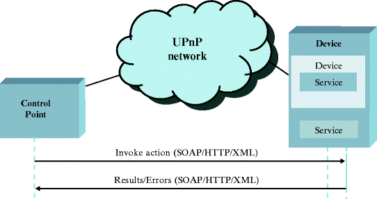
Control (University of Seville 2010)
-
5.
Eventing
Eventing can notify a control point when the state of a device changes. As explained above, a service description contains a list of variables that models the state of the service. If any of these variables is configured to report an event (evented variable), the service publishes updates when any of these variables are modified.
Eventing uses a publisher/subscriber model in which the control points can subscribe to events sent by a service. The services publish event notifications to subscribers. An event is a message sent from a service to the subscribed control points. The events inform the subscribed control points about the state changes in the services.
A control point that wants to be notified about the changes in the variable’s state subscribes to an event source by sending a subscription request to the URL of the events, which is contained in the corresponding device description. If a service accepts the subscription request, it responds with a SID and the duration of the subscription. The SID allows the control point to refer to the subscription in subsequent requests to the service, such as renewing or cancelling the subscription (Jeronimo 2004). Eventing protocol is a GENA and is used over the TCP layer, which guarantees message delivery to the subscriber. Figure 4.7 presents a diagram of this process.
Fig. 4.7 
Eventing (University of Seville 2010)
-
6.
Presentation
Presentation is considered as an optional step. A control point may monitor a device or check its status through the presentation of a webpage in HTML. If a device has a presentation page, control points may load presentation pages in a browser and these allow users to check and control the device. To retrieve a presentation page, the control point issues an HTTP GET request to the presentation URL and the device returns a presentation page (Microsoft) (see Fig. 4.8).
Fig. 4.8 
Presentation (University of Seville 2010)
It is also interesting to review UPnP applications developed in recent years to understand the interoperability provided by this architecture. For example, Maestre and Camacho (2009) state that different consumer electronic devices have been developed using UPnP architecture. De la Pinta et al. (2011) show that the Roomba robot has been successfully integrated into a UPnP framework. In addition, UPnP AV devices have been integrated into an OSGi platform (Kang et al. 2005). Another example of UPnP interoperability is the success of the DLNA protocol in multimedia services, which is derived from the UPnP architecture.


4.3.3 Jini
Jini is a service-oriented architecture developed by Sun Microsystems that provides an infrastructure for defining, publishing and searching for services on a network. Service Discovery (similar to UPnP service) is the main feature in the Jini technology, both in multicast mode and search mode for specific services. Jini uses the multiplatform feature from the Java platform to provide universal services, and it registers each one of them as serialized objects (service proxy) with its own interfaces. A Jini architecture diagram is shown in Fig. 4.9.

Jini architecture diagram (University of Seville 2010)
The main aims of this platform are discussed in Arnold (1999), which exposes its immediate services availability, the hardware abstraction, the service-based architecture and the simplicity. Jini is an easy protocol (Morgan 2000) as explained in Fig. 4.10.

Jini events (University of Seville 2010)
-
When a device is connected, it looks for a lookup service (Discovery) with which to register.
-
When a service provider locates a lookup service, it joins to it (Join). The service uploads a service proxy that a client would need to use its services, and the lookup service stores it.
-
When a client needs to locate and invoke a service, it asks the service for the lookup service, and it gives back the service proxy mentioned above.
-
Then, the client is able to interact with the service provider (during an specific time, in a shared way or in a exclusive one) through the proxy.
The purpose of the Jini architecture is to organize devices and software into groups inside a distributed and dynamic system. This simplifies the access, management and maintenance of each service offered by service providers. Some interesting concepts in a Jini system are presented below:
-
1.
Services
A Jini system consists of a set of services that can be used to perform a particular task. A service is an entity that can be used by one person, one program or another service. It may be a calculation, saved data, a communication channel with another user, a software filter, a hardware device or another user. Services communicate with each other using a service protocol (set of interfaces written in Java language).
-
2.
Lookup Service
Services are found through a lookup service. This is the central mechanism for the system and provides a mapping service that indicates the functionality provided by the services. A service is added to a lookup service using the discovery and join protocols. The service locates an appropriate lookup service (using the discovery protocol) and then joins to it (using the join protocol).
-
3.
Java RMI
This is a mechanism provided by Java to invoke remote methods. RMI is a Java extension of RPC. It provides remote communication between programs written in the Java programming language. The RMI subsystem also implements reference counting-based distributed garbage collection to provide memory management facilities for remote server objects.
RMI allows not only data to pass from one object to another through the network, but also whole objects to be sent and received, including their codes. Much of the simplicity of the Jini system is because of this ability to move code through the network, encapsulated in an object.
-
4.
Security
The Jini security model is based on the concepts of a master list and an access control list. Jini services are accessed by an entity – the principal – that generally refers to a particular user in the system. The access of an object to a service depends on the contents of the access control list associated with the object.
-
5.
Leasing
A lease grants access to a service for a certain period of time. Each lease contract is negotiated between the service user and provider as part of the protocol service, and it is released if the contract is not renewed.
-
6.
Transactions
A transaction can group a set of atomic distributed operations into a single unit. If one or more operations fail, the transaction is aborted and no partial results are written.
-
7.
Events
Jini supports distributed events. Objects may register to events in other objects. When an event occurs, a notification is sent to the objects that have been registered.
4.3.4 Web Services (WS)
WS is a technology that allows websites to use distributed applications and offers features such as access to the information and functionalities of any platform. At first, they were created to meet the need to standardize communication between different platforms and programming languages because earlier attempts such as CORBA had little success. In the case of CORBA, this was because there are certain limitations for more complex applications that require a security control or transaction management.
WS provide a standard means of interoperating between different software applications, running on a variety of platforms and frameworks. WS are functions or procedures that can be accessed via the web. Regardless of the programming language of the service and its platform, they enable the exchange of data and provide services between different applications.
Such a degree of interoperability is only possible using open protocols. WS are mainly used with HTTP because this is widely used and is rarely blocked by firewalls. WS are a set of protocols and standards used to exchange data between applications, and they are used on important websites for tasks such as e-commerce, web browsers and computer services by companies such as Google, eBay or Amazon. The W3C is responsible for managing the specifications. The main features of WS technology and its advantages and disadvantages are listed below:
-
It is supported by any platform and any programming language.
-
It is a W3C standard.
-
It provides functionality to websites.
-
It uses HTTP to transport data.
-
It uses standard elements for each of its components (SOAP, UDDI, Web Services Definition Language (WSDL) and XML).
-
-
One of the main advantages of WS is that they allow applications to communicate efficiently, regardless of the platforms used, offering greater interoperability. WS use standards and text-based protocols, which allows a better understanding and easier access to the data exchanged. They also use HTTP to allow the information to pass through firewalls without major complications. This fact together with the use of XML promotes interoperability.
-
However, WS are much less efficient than are CORBA or RMI because they make use of formats based on text, such as XML, which are not the best options to process tasks. Nevertheless, new WS standards may define more optimized protocols. Also they are not as developed as standards such as CORBA. Both HTTP and XML have a high run-time cost compared with other distributed applications approaches. Skipping the firewall security can also be seen as a drawback.
-
4.3.4.1 Components
WS use text-based standards and protocols, and this involves the components listed below. Figure 4.11 shows the diagram of the interactions between the entities and flows of the incoming and outgoing data of each component.

WS communication architecture (University of Seville 2010)
-
1.
WSDL
It is desirable that WS have information on the operations and data types involved. For this reason, WSDL is used. This is a standard adopted by the W3C that defines the public interface of WS. It is structured as follows:
-
Ports (<portType>): these describe the operations provided by WS. Its function is similar to an object-oriented class.
-
Messages (<message>): these define the data involved in an operation, where each message can have one or more parts. It is considered one of the parameters used in object-oriented programming.
-
Types (<types>): these define the data types involved in WS, using XML Schema, an XML language that accurately describes the structures and constraints of the XML file. It has been in the W3C since 2001.
-
Links (<binding>): these describe the message formats and the protocols for each one of the ports.
-
Operations (<operations>): these can be one-way, request-response (makes a request and waits for a response), request-response (receives a request and makes a response) or notice.
-
Services: these define a set of web service ports.
-
-
2.
UDDI
To register and publish WSDL we use Universal Description, Discovery and Integration (UDDI). This is a standard developed for the publication and registration of WS. Its way of working is similar to a database and has two different parts:
-
Registration of business:
-
White Pages (Overview)
-
Yellow Pages (categories of services)
-
Green Pages (business rules)
-
-
Registration of services
-
-
3.
SOAP
In addition, there was a need to define the way of exchanging data between different processes on different machines. For this task, we use the SOAP, which defines the format of the messages to send. It is independent of the transport protocol. The elements of a SOAP message are (Daconta et al. 2003):
-
Encapsulation of the message.
-
Description of the data coding.
-
Body, which contains the specific message of the application.
-
4.3.4.2 Applications
Websites ask WS for a series of functions. They are currently used in almost all websites and they provide most logic to the website. Another possible application of WS is for the control of robots. WS are used to control robots from anywhere in the world via the Internet through a user interface, which will provide the services offered by the robot as well as its status (Levine and Vickers 2001).
4.3.5 Semantic Web Services (SWS)
SWS were derived from the combination of WS with the emergence of the semantic web (Fig. 4.12). Tim Berners-Lee created the semantic web states that the “Semantic Web is not a separate web but an extension of the current one, in which information is given well-defined meaning, better enabling computers and people to work in cooperation” (Berners-Lee et al. 2001). WS meet the requirement of a specified syntax; however, they have a lack of semantics so they cannot resolve ambiguities. This is solved by using SWS, optimizing this way the reuse of WS and creating smarter websites, resulting in the concept of Web 3.0. This simplifies the sharing and integration of web resources.

The emergence of SWS (University of Seville 2010)
To represent knowledge, ontologies that structure information, resources or services based on the meaning of words emerge. This allows computers to interpret and process this information to work automatically.
The languages of high-level ontologies are backed by a formal logic, which makes sure that the ontology can be interpreted by the machines. This means that the computer and its software can interpret the semantics of the model without direct human intervention. The ontological software rises to the level of human conceptual knowledge; humans do not have to descend to the machine’s levels (Daconta et al. 2003).
SWS are an important line of the semantic web, which aim to describe not only information but also WS’s functionality ontologies and procedures: its inputs, outputs, conditions for implementation, effects produced or steps followed. These machine-processable descriptions will automate the discovery, composition and implementation of services, as well as the communication among them. The semantic web has emerged to provide the syntactic web with semantic intelligence and has the following main features:
-
Automatic data interpretation.
-
Ontologies as data models.
-
Discovery, selection and automatic service composition.
-
Service implementation through the web.
4.3.5.1 Required Functionalities
-
Publication of service descriptions.
-
Services discovery.
-
Service selection.
-
Composition of services.
-
Resolution of problems caused.
-
Implementation of automated services.
-
Monitoring of implementation.
-
Compensation.
-
Substitution of services for similar ones.
-
Verification of implementation.
4.3.5.2 Main Technologies
-
Web Ontology Language (OWL-S). This is an ontology based on OWL, which is a markup language for publishing and sharing data using ontologies. It was created by DARPA (2007), which is part of the US Department of Defense, where they automate tasks such as the discovery, invocation and composition of WS.
-
Web Service Modeling Ontology (WSMO). This is a conceptual model for the relevant aspects of SWS and it belongs to the European Semantic Systems Initiative. The WSMO working group includes the technology of Web Service Modeling Language, which formalizes the WS that model the ontology (Lara et al. 2004). Its main components are:
-
Goals. These are the customer’s aims when they access the web service.
-
Ontologies. A formal description of the semantics used by all components.
-
Mediator. These are connectors that provide interoperability among different ontologies.
-
WS. These can include the functional and usage descriptions of WS.
-
OWL-S has a weak point in the architecture because it is undefined. It also has little development in comparison with WSMO. Its difficulty is also higher and less intuitive than WSMO is. However, its groundings of use are well developed. However, WSMO is not mature in key areas of use. It has a robust and flexible architecture for the consumer in contrast to OWL-S. It has defined important aspects such as languages and mediation. There are also plans to automate the creation of WS based on WSMO to semi-automate this process, thereby saving money, time and resources; the same as in the IRS III project.
-
4.3.6 RMI
RMI emerged from the need to communicate among different objects, and it is implemented on different machines as happens on distributed systems. Therefore, this technology is a remote invocation of Java objects. The initial version of Java RMI required a JVM in both the origin and destination machines (Cheng-Wei et al. 2004).
After the RMI-IIOP was developed, it was added to the RMI, providing it with the best features of CORBA. RMI is pure Java and since it does not support other languages, CORBA emerged. The adaptation to a distributed system has not prevented the continued development of RMI as a secure system. The main characteristics of RMI are:
-
Simple, easy to write and easy to maintain.
-
Transparency, because the distribution of objects and parameters passing is transparent to the programmer.
-
Pass an object by value (as parameters of methods).
-
The definition of interfaces is done directly in Java.
-
Implementation in Java.
-
Independence of the communication protocol.
-
Separation between interface–client and implementation–server.
-
Naming service.
4.3.6.1 Architecture
RMI is a layer architecture made of a stub/skeleton layer, a remote reference layer and a transport layer. The programmer only interacts with the application layer. The RMI system manages the three previous layers (see Fig. 4.13), which could be replaced by others with the same function without altering the rest.

RMI architecture (University of Seville 2010)
4.3.6.2 Components
-
1.
IIOP
RMI allows the programming of CORBA servers and applications via the RMI API. It is possible to work entirely in the Java programming language using the Java Remote Method Protocol as a transport or to work with any other CORBA implementation using IIOP Java RMI over IIOP.
RMI-IIOP is designed for developers who program in Java and want to use the RMI interfaces using IIOP as the transport layer. The RMI-IIOP interoperability with CORBA objects implemented in other languages is available only if all the remote interfaces have been previously defined as Java RMI interfaces (Oracle 2010).
4.3.6.3 Application
At the University of Bielefeld, Germany, one research group has integrated memory-based software for the development of autonomous robots. This is an approach to an architecture of autonomous mobile robots operating in human environments. It replaced the use of data on a closed chain based on the long- and short-term memory. RMI was used for the exchange of critical information, such as the module that controls the hardware. RMI also allows the system to estimate when the configuration has been completed. The system can then send information on the result of the configuration (Spexard et al. 2008).
Westhoff et al. (2004) focuses on task-level programming and monitoring robots in their daily operations. It is not a framework limited to robots and it could be used in other distributed environments. During its development, the authors took advantage of technologies available in Java, such as Jini, RMI and Java Native Interface. Woo et al. (2003) supported Java RMI over Bluetooth, GPRS and WLAN technologies. As a conclusion of this, the good work of Java RMI was tested in heterogeneous wireless environments, allowing parallel and distributed control.
In a study by researchers at the Information and Communications University in Korea, RMI is used to access external ontologies in the development of a self-expandable software. This kind of software is useful for intelligent robots for two reasons. First, they study their environments and then they decide their appropriate behavior based on what they have learnt about their surroundings.
DEVS/RMI is a distributed, self-adaptive and reconfigurable simulation environment for engineering studies. It is based on the standard implementation of DEVS, in which Java RMI supports the synchronization of local and remote objects. It is designed for the intensive testing of programs, and this is the reason for it supporting dynamic models (Zhang et al. 2005).
4.3.7 Other Computer Science Standards
4.3.7.1 DH Compliant
DH Compliant (DH Compliant 2010) is a system providing interoperability between all devices existing in a home network. It is based on the UPnP architecture and is currently under development by the University of Oviedo, the University of Seville and a consortium of companies composed of Ingenium (Ingenium 2010), Domotica Davinci (Domotica Davinci 2010), MoviRobotics (MoviRobotics 2010), (Applied Research Associates) (ARA 2010) and the Cartif Foundation (Cartif 2010). The main goal of DH Compliant architecture (Fig. 4.14) is to integrate consumer electronics devices, robots, sensors and other interesting components that may be useful in a home automation framework.

DH Compliant architecture (University of Oviedo 2010)
The aim of the DH Compliant system is development and implementation that allows the integration of service robots within the digital home. This architecture will provide interactions between robots and digital homes to make life easier, more secure and more comfortable. This protocol integrates the intelligence of a UPnP control point and the functionality of a UPnP device in a single DHC device. This entity network is managed by other entities that provide new services such as the localization service, energy-saving service and the service for collaborative tasks between robots.
4.3.7.2 OSGi
OSGi (OSGi Alliance 2003) is a module system for the Java environment that implements a components model, which needs JVMs. OSGi is based on a layer model that includes, among others, a bundles layer that provides the applications and components as packages (i.e. jar files), a services layer that provides communication between bundles through Java objects, and modules and security layers.
OSGi may be a good alternative for the development of complex systems because of its versatility and cross-platform feature (one JVM in each network node would be necessary to run the application). Any framework that implements the OSGi standard must provide applications modularity to decompose the application into small packages. Each package is a collection class (jar and settings files). The framework is conceptually divided into the following areas:
-
Bundles. This is a set of Java classes and additional resources.
-
Services. This connects bundles dynamically. There is also an API for services management.
-
Lifecycle. This is the API to manage the lifecycle and it spans install, start, stop, update and uninstall.
-
Modules. This defines how bundles import and export code.
-
Security. This limits bundles’ functionality to predefined capabilities.
-
Execution environment. This defines what methods and classes are available on a specific platform.
Some examples of OSGi uses can be found in the literature. Gu et al. (2004) discussed an intelligent system (SOCAM) based on ontologies integrated with OSGi to build a system that can deliver and manage context-aware services in a smart-home environment. Meanwhile, Kang et al. (2005) fuse UPnP AV, which is used to provide media services, with OSGi, which manages each UPnP entity as a bundle.
References
Albus J, Huang H, Messina E (2002) 4D/RCS A reference model architecture for unmanned vehicle systems, version 2.0, NISTIR 6910, National Institute of Standards and Technology, Gaithersburg, MD
Albus J, Murphy K, Lacaze A, Legowik S, Balakirsky S, Hong T, Shneier M, Messina E (2002) 4D/RCS sensory processing and world modeling on the Demo III experimental unmanned ground vehicles. In: Proceedings of the 2002 IEEE international symposium on intelligent control, pp 885–890. doi: 10.1109/ISIC.2002.1157879
Arnold K (1999) The Jini architecture: dynamic services in a flexible network. In: Proceedings of the 36th annual ACM/IEEE design automation conference, pp 157–162. doi: 10.1145/309847.309906
Cheng-Wei Chen, Chung-Kai Chen, Jyh-Cheng Chen, Chien-Tan Ko, Jenq-Kuen Lee, Hong-Wei Lin, Wang-Jer Wu (2004) Java RMI over heterogeneous wireless networks. IEEE Int Conference Commun (ICC) 3:1391–1395. doi:10.1109/ICC.2004.1312740 DOI:dx.doi.org
Gu T, Pung HK, Zhang DQ (2004) Toward an OSGi-based infrastructure for context-aware applications. IEEE Pervasive Comput 3(4):66–74. doi:10.1109/MPRV.2004.19
Kang DO, Kang K, Choi S, Lee J (2005) UPnP AV architectural multimedia system with a home gateway powered by the OSGi platform. IEEE Trans Consum Electron 51(1):87–93. doi:10.1109/TCE.2005.1405704
Kim D, Lee J, Kwon WH, Yuh IK (2002) Design and implementation of home network systems using UPnP middleware for networked appliances. IEEE Trans Consum Electron 48:963. doi:10.1109/TCE.2003.1196427
Knoop S, Vacek S, Zöllner R, Au C, Dillmann R (2004) A CORBA-based distributed software architecture for control of service robots. Proc Int Conf Intell Robots Syst 4:3656–3661. doi:10.1109/IROS.2004.1389983 DOI:dx.doi.org
Koren Y, Borenstein J (1991) Potential field methods and their inherent limitations for mobile robot navigation. IEEE Int Conf Robot Automation 2:1398–1404. doi:10.1109/ROBOT.1991.131810
Lara R, Roman D, Polleres A, Fensel D (2004) A conceptual comparison of WSMO and OWL-S, vol 3250. Springer, pp 254–269. doi: 10.1007/978-3-540-30209-4_19
Morgan S (2000) Jini to the rescue [computer network interconnection technology]. IEEE Spectr 37(4):44–49. doi:10.1109/6.833027
Shoemaker CM, Bornstein JA (1998) The Demo III UGV program: a testbed for autonomous navigation research. In: Intelligent control (ISIC).In: Proceedings held jointly with IEEE international symposium on computational intelligence in robotics and automation (CIRA), Houghton, intelligent systems and semiotics (ISAS), Gaithersburg, pp 644–652. doi: 10.1109/ISIC.1998.713784, doi:dx.doi.org
Takeda K, Nasu Y, Capi G, Yamano M, Barolli L, Mitobe K (2001) A CORBA-based approach for humanoid robot control. Ind Robot Int J 28(3):242–250. doi:10.1108/01439910110389407 DOI:dx.doi.org
Vinoski S (1997) CORBA: integrating diverse applications within distributed heterogeneous environments. IEEE Commun Mag 35:46–55. doi:10.1109/35.565655 DOI:dx.doi.org
Westhoff D, Scherer T, Stanek, H, Zhang J, Knoll A (2004) A flexible framework for task-oriented programming of service robots. IN VDI BERICHTE, 1841. doi: 10.1109/ICIA.2005.1635052
Woo E, MacDonald BA, Trepanier F (2003) Distributed mobile robot application infrastructure. In: Proceedings of international conference on intelligent robots and systems, Las Vegas, vol 2, pp 1475–1480. doi: 10.1109/IROS.2003.1248852 DOI:dx.doi.org
Zhang Z, Cao Q, Zhang L, Lo C (2009) A CORBA-based cooperative mobile robot system. Ind Robot Int J 36(1):36–44. doi:10.1108/01439910910924657
Bottazzi S, Caselli S, Reggiani M, Amoretti M (2002) A software framework based on real-time CORBA for telerobotic systems. In: IEEE international conference on intelligent robots and systems, Lausanne, pp 3011–3017
Daconta MC, Obrst LJ, Smith KT (2003) The semantic web: a guide to the future of XML, Web services, and knowledge management. Wiley, Indianapolis
English W (2007) Joint Architecture for Unmanned Systems (JAUGS). Reference architecture specification, Vol II, version 3.3
Everett HR, Laird RT, Carroll DM, Gilbreath GA, Heath-Pastore TA, Inderieden RS, Tran T, Spexard TP, Siepmann FHK, Sagerer G (2008) Memory-based software integration for development in autonomous robotics. In: Burgard W, Dillmann R, Plagemann C, Vahrenkamp N (eds) Intelligent autonomous systems 10: IAS-10. IOS Press, Amsterdam
Gothing G, Hurdus J (2006) Implementation of JAUS on a cadillac SRX using a potential fields architecture. AUVSI
Henning M, Vinoski S (1999) Advanced CORBA programming with C++. Addison-Wesley Professional, Reading, MA
Jeronimo M, Weast J (2003) UPnP design by example. A software developers guide to universal plug and play. Intel Press, Hillsboro
OSGi Alliance (2003) OSGi service platform: the OSGi alliance. IOS Press, Ohmsh
ARA (Applied Research Associates). http://www.ara.com/. Accessed 2 Dec 2010
Blind Driver Challenge (2010). National Federation of the Blind. http://www.blinddriverchallenge.org/bdcg/Default.asp. Accessed 3 Dec 2010
Bray T, Paoli J, Sperberg-McQueen CM, Maler E, Yergeau F (2008) Extensible markup language (XML) 1.0, 5th edn. W3C Recommendation 26. http://www.w3.org/TR/2008/REC-xml-20081126/. Accessed 2 Dec 2010
Carroll DM, Mikell K, Denewiler T (2004) Unmanned ground vehicles for integrated force protection. In: SPIE Proceedings of the 5422Cartif. http://www.cartif.com/. Accessed 2 Dec 2010
Cartif (2010) Fundación CARTIF – Centro Tecnológico Cartif. http://www.cartif.com/index.php/es/quienes-somos/centro-tecnologico-cartif.html. Accessed 1 Dec 2010
CDL Systems, NATO STANAG 4586 (2010) http://www.cdlsystems.com/index.php/stanag4586. Accessed 3 Dec 2010
Clark MN (2005a) JAUS implementation: robots gather for successful interoperability experiment. IEEE Rob Autom Mag. www.openjaus.com/. Accessed 2 Dec 2010
Clark MN (2005b) JAUS compliant systems offers interoperability across multiple and diverse robot platforms, unmanned systems North America conference, Baltimore, MD. www.openjaus.com/. Accessed 2 Dec 2010
DARPA (2007) DARPA urban challenge. http://www.darpa.mil/grandchallenge/index.asp. Accessed 3 Dec 2010
De la Pinta JR, Maestre JM, Camacho EF, Alonso IG (2011) Robots in the smart home: a project towards interoperability. International Journal of Ad Hoc and Ubiquitous Computing (IJAHUC) Special issue on The smart digital home, (forthcoming)
Defense Update (2007) STANAG 4586 – NATO complient ground control system for UAV. International, Online Defense Magazine. http://defense-update.com/products/s/stanag_4586.htm. Accessed 3 Dec 2010
DH Compliant (2010) http://www.dhcompliant.com/. Accessed 2 Dec 2010
Domotica Davinci (2010) http://www.domoticadavinci.com/. Accessed 2 Dec 2010
Ingenium (2010) http://www.ingeniumsl.com/website/es/index.html. Accessed 2 Dec 2010
Jeronimo M (2004a) It just works: UPnP in the digital home. http://www.artima.com/spontaneous/upnp_digihome.html. Accessed 12 Dec 2010
Jeronimo M (2004b) It just works: UPnP in the digital home. J Spont Net. http://www.artima.com/spontaneous/upnp_digihome.html. Accessed 2 Dec 2010
Maestre JM, Camacho EF (2009) Smart home interoperability: the domoesi project approach. Int J Smart Home 3(3):31–44
Members of the UPnP Forum (2008) UPnP device architecture 1.1. http://www.upnp.org/specs/arch/UPnP-arch-DeviceArchitecture-v1.1.pdf. Accessed 2 Dec 2010
MoviRobotics (2010) http://www.movirobotics.com/. Accessed 2 Dec 2010
Nato Stanag 4586 (2007) Standard interfaces of Uav control system (Ucs) for Nato Uav interoperability
Nguyen HG (2005) Overview and highlights of robotics research and development at the space and naval warfare systems Center, San Diego. SPAWAR systems center. http://handle.dtic.mil/100.2/ADA433768. Accessed 1 Dec 2010
OMG (Object Management Group) (1998) CORBAservices: common object services specification. http://www.ing.iac.es/~docs/external/corba/CorbaServices.pdf. Accessed 2 Dec 2010
Oracle (2010) When should I use RMI-IIOP? http://java.sun.com/j2se/1.5.0/docs/guide/rmi-iiop/rmiiiopUsing.html. Accessed 2 Dec 2010
SAE (2010) Society of Automotive Engineers. http://www.sae.org/. Accessed 2 Dec 2010
SAE, JAUS History and Domain Model (2006) Architecture framework committee. http://www.sae.org/. Accessed 2 Dec 2010
SAE, JAUS Mobility Service Set (2009) Information Modeling and Definition Committee. http://www.sae.org/. Accessed 3 Dec 2010
SAE, JAUS/SDP Transport Specification (2009) Network Environmental Committee. http://www.sae.org/. Accessed 5 Dec 2010
Schlenoff C, Albus J, Messina E, Barbera AJ, Madhavan R (2006) Using 4D/RCS toaAddress AI knowledge integration. AI Magazine, 27
TORC. ByWire XGV (2010) – Hybrid escape drive-by-wire platform. http://www.torctech.com/. Accessed 3 Dec 2010
University of Oviedo. Infobotica Research Group (2010) DhCompliant stack architecture v0.4. http://156.35.46.38/data/files/Architecture/DHCompliantArchitecture0433.pdf. Accessed 3 Dec 2010
University of Seville (2010) Interoperability diagrams (technical report). http://nyquist.us.es/dhcompliant/Interoperability_diagrams.pdf. Accessed 3 Dec 2010
UPnP Forum. http://www.upnp.org/. Accessed 2 Dec 2010
Wade RL (2006) Joint architecture for unmanned systems. Aviation and missile research, development and engineering Center (AMRDEC). http://www.dtic.mil/ndia/2006targets/Wade.pdf. Accessed 3 Dec 2010
Zhang M, Zeigler BP, Hammonds P (2005) DEVS/RMI-An auto-adaptive and reconfigurable distributed simulation environment for engineering studies. ITEA J. http://citeseerx.ist.psu.edu/viewdoc/summary?doi=?doi=10.1.1.137.5872. Accessed 30 Nov 2010
Baity S (2005) Development of a next-generation experimentation robotic vehicle (NERV) that supports intelligent and autonomous systems research. Master of Science thesis, Mechanical Engineering, Virginia Tech, Virginia
Cummings ML, Kirschbaum AR, Sulmistras A, Platts JT (2006) STANAG 4586 human supervisory control implications, Air and Weapon Systems Department, Dstl Farnborough & the Office of Naval Research
Faruque RR (2006) A JAUS toolkit for LabVIEW, and a series of implementation case studies with recommendations to the SAE AS-4 Standards Committee. Master of Science thesis, Mechanical Engineering, Virginia Tech, Virginia
Levine J, Vickers L (2001) Robots controlled through web services: a technogenesis summer research
Author information
Authors and Affiliations
Corresponding author
Rights and permissions
Copyright information
© 2011 Springer Science+Business Media B.V.
About this chapter
Cite this chapter
Alcalá, M.R.F., Maestre, J.M., de la Pinta, J.R. (2011). Integration of Service Robots in the Smart Home. In: Service Robotics within the Digital Home. Intelligent Systems, Control and Automation: Science and Engineering, vol 53. Springer, Dordrecht. https://doi.org/10.1007/978-94-007-1491-5_4
Download citation
DOI: https://doi.org/10.1007/978-94-007-1491-5_4
Published:
Publisher Name: Springer, Dordrecht
Print ISBN: 978-94-007-1490-8
Online ISBN: 978-94-007-1491-5
eBook Packages: EngineeringEngineering (R0)