
Abstract
Construction of dams and reservoirs in karst is historically known as a very risky task. Inspite of very detailed geophysical investigations and repeated sealing treatments, the possibility for dam failure cannot be eliminated. In the karst environment, with its highly random distribution of dissolution features, some uncertainties always remain. The final determination of the adequacy of sealing measures comes after the first reservoir impoundment or even later. In many worldwide examples, watertightness treatment during dam construction was only partially successful, with some remedial work after impoundment being quite common. However, in some cases, the problem is simply too complicated and cannot be overcome. Special approaches have to be undertaken in order to prevent seepage from reservoirs. The key elements are a good geological map and proper geophysical investigations. These investigations are key prerequisites of dam construction in karst and cutting costs through restricting them usually results in increasing the chance of project failure. To deal with karst successfully, innovation, engineering practice, execution feasibility, and commercial understanding have to be undertaken. Grouting alone is definitely not adequate in the case of large karst conduits. Special treatment of large caverns and flexibility during grout curtain execution, including modifications and adaptations on the basis of the geological findings, should be the standard procedure for dam construction in karst to minimize risk. Such an approach is the basic worldwide rule in the fight against leakage from dam sites and reservoir abutments.
Access provided by Autonomous University of Puebla. Download chapter PDF
Keywords
These keywords were added by machine and not by the authors. This process is experimental and the keywords may be updated as the learning algorithm improves.
1 Introduction
In many karst regions of the world, the only resource available for economic development was the large groundwater aquifer. Because of that, karst terranes have been modified and adapted through a range of human activities to meet such needs as drinking water, flood control, irrigation, and hydroelectric power. The subsequent development of karst groundwater and rudimentary investigations of this resource date back several millennia to old Greek, Persian, and Chinese times. However, construction of large dams and reservoirs in karstified rocks is relatively new. The large projects started during the first part of twentieth century, but the intensive construction period started after World War II.
The right geological conditions are the basis for the construction of safe dam structures and watertight reservoirs. Due to the specific and complex nature of karst, it is not easy to select sites for dams or reservoirs that would be acceptable, without additional remedial measures. Successful solutions require serious and complex geological, hydrogeological, and geotechnical investigation programs and close cooperation of a wide spectrum of scientists and engineers. Each karst region is unique, and changes in the physical landscape can be unpredictable and can occur very rapidly. It has been found that some methods already applied to other geological environments had to be modified for karst settings. Finding new and better investigation methods in geology, hydrology, and geophysics was of great importance.
During dam, reservoir, and tunnel construction, unique problems are posed by the presence of caverns. The most frequent technical difficulties are water leakage at dam sites and from reservoirs, and breaching by water and mud during tunneling and other underground excavations. Natural or induced subsidences are also frequent failures related to characteristic structures in karst (Sharp 1997; Romanov et al. 2003; Beck 2004; Criss et al. 2008).
Because of the nature of karst, it is not easy to select the dam site location that would be acceptable for construction without serious, large-scale underground or surface impermeabilization. The common underground structures are grout curtain, plugging of karst caverns and channels, and construction of different cut-offs. The common geotechnical methods at the surface are compaction of the bottom surface, shotcrete, grouting, geosynthetics, plugging, and cylindrical dams or dikes to isolate large swallowholes.
Construction of dams in evaporates is a particularly risky task because solution rates are orders of magnitude higher compared to other carbonates. A number of dam failures in evaporates has resulted in large-scale mortality and great financial loses. Technology of watertightness remedial works in evaporates is still rudimentary compared to other karstified limestone and dolomites.
2 Overview of Dam and Reservoirs Construction in Karst
Inadequate selection of the construction site results in either a structural failure causing the project to be abandoned or leads to long, unpredictable remediation works. From the experiences at the very beginning of dam construction in karst during the first part of twentieth century, karstified rock has been considered unsuitable for these kinds of projects. Dried reservoirs or reservoirs with unacceptably high leakage confirm that opinion: McMilan Dam (USA, 1893), Hales Bar Dam (USA, 1913), Camarasa Dam (Spain, 1920), Montejaque Dam and Reservoir (Spain, 1920), Great Falls Dam (USA, 1925), Fodda Dam (Morocco, 1928), Vrtac Reservoir (Montenegro, 1952), May Dam (Turkey, 1959), Cevizli and Keban Dam (Turkey, 1979/80), Lar Dam (Iran, 1978), Kalecik Dam (Turkey, 2001). These examples have led to the opinion that reservoirs in karst may fail to fill, despite an extensive investigation program and sealing treatment. Since the risk due to karstification could not be eliminated, the Darwin Project in Tasmania was abandoned in 1920. However, after several phases of long-term investigations (1950, 1983, 1986, 1989), construction was finished and reservoir filled in 1992 (Giudici 1999). Another dam project in Tasmania, the Lower Gordon Dam, was aborted due to legal and environmental reasons in 1983. This dam would have flooded caves of great archeological importance (Kiernan 1988).
After World War II started an era of intensive dam construction in karst environments (Ford and Williams 2007). Many dam projects have been successfully developed in countries with large karst regions, mostly at Dinarides, Helenides, Taurides, Zagros, and China. Nevertheless, the road to those successes was, in some cases, paved with failures. New investigation techniques and new sealing technologies were developed and applied in different karst projects. Large-scale underground or surface impermeabilization techniques were applied. Long and deep grout curtains were constructed, including plugging of underground caverns and channels. In the case of surface sealing, the most common geotechnical methods were clayey blankets, shotcrete blankets, different kinds of geotextiles, and surface grouting.
However, in the case of dam and reservoir construction in karst, the risk component cannot be eliminated in spite of detailed and long-term investigations. The risk can be minimized to an acceptable level, but never absolutely eliminated. Consequently, proper risk reduction strategy is important during all phases of dam and reservoir construction. Changes caused by dam and reservoir construction impact ecological, infrastructure, social, and political systems. Some of these impacts are positive and predictable, but they can be also negative and unpredictable. This text is focuses on engineering problems.
3 Role of Geological and Geomorphological Conditions
Carbonate rocks and evaporates are prone to the intensive fluvial erosion and chemical dissolution at the same time. Many gorges and deep canyons are developed in those rock masses. From the geomorphological, geological engineering, and geotechnical viewpoint, limestone gorges are perfect for dam construction, particularly for concrete dams. However, in many cases, karst processes deteriorate hydrogeological properties of those rock masses.
Intensity and depth of karstification depends on different geological properties and processes: lithology, structural composition, tectonic (particularly recent) movement, density of discontinuities, position of important erosion base levels, corrosion (dissolution), and hydraulic action (Milanović 1981). Karst is a product of processes that operate on continental land masses, especially when the land masses are uplifted above sea level. In the most complex cases, karstification occurred in discontinuous phases of bedrock uplift or submersion caused by epirogenic and orogenic movements. For instance, the Dinaric geosyncline karst was formed over various discontinuous periods, generating a combination of the recent karst and stratigraphically different paleokarsts.
Two different types of karst porosity are most common:
-
1.
Vuggy porosity found in limestone bedrock. Some of these vugs are interconnected, but most are isolated. The hydrogeological role of vuggy porosity is secondary, hence it can be easily grouted.
-
2.
Classical karst porosity, represented by open solution channels, discontinuities enlarged by solution, and caverns developed along the faults, joints, and beddings, which create a well-connected network of conduits. This network represents the highest potential for leakage pathways.
According to generalized geomorphological and geological properties, deep and narrow canyons usually feature shallower karstification than wide river valleys or karst depressions (poljes). The deepest erosion base levels in narrow canyons usually correspond to riverbeds, which are manifestations of the surrounding karst aquifer and its water table, e.g., Piva Dam (Montenegro), Tange Duk (Iran), and Grančarevo Dam (Bosnia-Herzegovina, hereafter B-H). The same conclusion has been drawn by Chinese karstologists. However, this is not a hard and fast rule as there are some very narrow dam sites, such as the Abol Abas (Iran), where the groundwater level (GWL) is 50 or more meters beneath the bottom of the dam site. A deeper water table allows greater karstification between the GWL and the surface of the bedrock, causing engineers to design a more comprehensive grout curtain below the dam, increasing costs and time of construction.
Below the wide karst river valleys, situated at high elevation, deep karstification can be expected. The hanging rivers along these valleys are mostly temporary. Depending on the position of the surrounding erosion base levels, the carbonate rock mass can be karstified well below the valley floor, such as Keban (Turkey) and Lar (Iran).
Dam sites located at the upstream section of river bends need greater exploration than those in the straight part of the river valley. During the karst aquifer evolution, the section of river valley downstream from a bend plays a role of local base level of erosion. Gradients between upstream and downstream river sections are much steeper than along the riverbed. If monocline limestone structures occur between the upstream and downstream river sections, then underground hydrogeological connections through the karst channels are to be expected, e.g., Keban (Turkey), Salakovac (B-H), Karun III (Iran) and Dokan (Iraq).
On a regional scale, structural relationships have an important role in forming the hydrogeological properties in a karst region. If an anticline structure exists between the reservoir and the lower erosion base level, the possibility for karstification perpendicular to the structure is considerably reduced. Of particular importance is the reservoir watertightness, which for many dam sites and reservoirs is based on the hydrogeological role of large anticlines, e.g., Karun III and Salman Farsi Dams (Iran), Bileća Reservoir (B-H). If the folding structures are extensively compressed by tectonic forces with prevailing horizontal stress, then the anticline cores will be resistant to karst processes. The karst channels are mostly developed in the direction of axial planes rather than perpendicular to them. An example of the hydrogeological role of such geological settings is the “Lastva anticline,” which has a core predominantly of dolomite (Fig. 3.1). This structure acted as a hydrogeological barrier between reservoir and lower erosion base levels. The huge “Bileća Reservoir” in B-H, situated completely on karstified limestone, operates without leakage because of positive hydrogeological role of this type of geological structure (Milanović 2006).

Right abutment of “Bileća” reservoir and position of lastva anticline, B-H; 1 Limestone; 2 Dolomite; 3 Large spring; 4 Small permanent spring; 5 Temporary spring; 6 Ponor; 7 Karst shaft; 8 Borehole; 9 Anticline; 10 Regional fault; and 11 General direction of underground flows
In contrast, large karst depressions (poljes) are hydrogeologically complex places for reservoir construction. Long zones with concentrated infiltration points (ponors and estavelles) with swallowing capacities ranging from a few m3/s to 100 m3/s are common hydrogeological features along the border of poljes. During the dry season, the water table is deep beneath the bottom of a possible reservoir. If estavelles are prevailing hydrogeological features, the problem of artificial impermeabilization is more complex than in the case of only ponors. In the case of estavelles associated with huge uplift, building watertight structures are problematic. Active uplift can easily demolish these structures or create new openings in the protected estavelles.
Huge caverns and a deep GWL below the dam foundation and bottom of reservoirs are common in karst. Some examples are listed below:
-
(a)
In the case of Keban Dam (Turkey), the largest cavity, called the Crab Cavity, was discovered at a depth of 320 m below the crest level. This cave was filled with 64,000 m3 of concrete and injection solids.
-
(b)
The lowest GWL is 200 m below the Mornos Reservoir storage level (Greece).
-
(c)
Below the Lar Dam site (Iran), a large cavern, 27 m high and 68 m wide, was discovered at a depth of 210 m below the riverbed. The volume of the cavern was determined to exceed 90,000 m3. A few other caverns have been discovered at the depth of 250–430 m below the riverbed.
-
(d)
In the case of Perdika Reservoir (Greece) the GWL was about 70 m below the reservoir bottom, in the karstified bedrock.
-
(e)
Numerous large water-bearing karst channels were detected ∼180 m beneath the river level at Canelles Dam site (Spain).
-
(f)
At Wujiangdu Dam site (China), many karst cavities, particularly in the left bank, are found down to the depth of about 250 m beneath the riverbed.
-
(g)
Part of Akkopru Reservoir in Turkey is located on highly karstified limestone with number of vertical shafts. GWL in this part is about 100 m below the reservoir bottom.
-
(h)
The water table below the Hutovo Reservoir in B-H, in drought conditions, is more than 100 m deep. With abrupt rising of the water levels, the air current from piezometers can reach a velocity of 15 m/s.
-
(i)
Large karst caverns were detected at depth of more than 100 m below the Chichik Dam site (Uzbekistan).
In some cases, reservoir construction in closed karst depressions was abandoned after extensive subsurface investigations or its designation was changed. Due to huge leakage through the number of estavelles from the Vrtac Reservoir in Montenegro, the reservoir’s role has been redesigned for temporary retention rather than a permanent water reservoir (Milanović 2010). Because of karstified limestone at one section of Aliakmon River (Elati basin), the Ilarion Dam project (Greece) was suspended. Detailed investigations and analysis have resulted in the relocation of some projects such as the Miatlinskaya Dam (Russia) and the Havasan Dam (Iran) (Milanović 2010). The seepage problems with Hales Bar Dam (USA) started immediately after the first filling (1905). Unable to overcome this problem, the dam was demolished in 1968 and replaced with Nickajak Dam, 10 km downstream (Bruce 2003).
One of the most complex problems related to the geology of some dam sites and reservoirs is karstification created by the simultaneous influence of phreatic and thermal waters, e.g., Višegrad Dam (Bosnia), Salman Farsi and Karun IV Dams (Iran), Pengshui Dam (China), Chichik Dam (Uzbekistan), and Hamam Grouz (Algeria). Sources of the heat for these thermal waters are usually very deep and detection of its position is a complicated task. Consequently, the location of karst features created by thermal water also needs complex investigations, particularly deep boreholes for thermal measurements (for more information, see Ballard et al. 1983 and Fazeli 2007). For successful grout curtain design, particularly its inclination and depth, the exact determination of the location of karst channels produced by the upward hot water flows is essential.
In China, construction of a number of underground dams and reservoirs has taken place. Lu (1986) and Yuan (1999) show that these dams have storage capacities between 1 × 10⁵ and 1 × 10⁷ m3. One of the largest underground reservoirs was built on the Linlangdong underground river in Qiubei, Yunnan Province, by constructing a 15 m high underground dam (1955-1960) with an underground flow discharge varying from 23.8 to 100 m3/s. Underground dams have also been constructed for Yuhong Power Plant (Hunan), Beilou Power Plant (Quangsi), and Wulichong Reservoir (Yunnan Province). Several underground dams have also been constructed in the limestone in Japan (Okinawa and Miyako Islands).
One of the largest underground projects is the Ombla Underground Dam and Reservoir (Croatia), which takes discharge (Q) from the Ombla Spring (mean Q = 24.4 m3/s). At the dam, deep flysch sediments act as a hydrogeological barrier and get progressively higher on each side of the spring, forming a “V” cross-sectional profile. All structures (dam, reservoir, and power plant) are situated underground. The dam’s grout curtain, including cut-off structures and concrete plugs, has been tightly connected to the impervious flysch sediments. The crest elevation of the arch-like underground dam is 100 m above sea level with a grout curtain 150–200 m below sea level. Underground storage water volume ranges between 10 × 106 m3 and 12 × 106 m3.
One of specific characteristics of reservoirs in karst is large storage deep within the reservoir banks. This storage is the active part of the reservoir. Based on calculation of Gunay et al. (1985) the bank storage rate was determined to be 35–40% of water stored in the Oymapunar Reservoir (Turkey). In the case of Bileća Reservoir (B-H), the bank storage was estimated to be 10–15% of water stored in the reservoir.
Due to dam construction in karst, large and permanent karst springs have been affected by the new regional, higher hydraulic head created by the reservoir. In those cases, it was important to understand whether any leakage may occur. Dumanli Spring (Q = 25 to >100 m3/s) was flooded by 120 m from the Oymapinar Reservoir (Turkey; Trebišnjica Spring (Q av = 80 m3/s) had an increase in the hydraulic head of 75 m from the Bileća Reservoir (B-H); Pivsko Oko Spring (Q av = 25.5 m3/s) was flooded by a 70 m water column of the Piva Reservoir (Montenegro). After impounding and many years of operation of these aforementioned reservoirs, no negative influence of the spring submergence was observed, especially with regard to water losses from reservoirs.
4 Investigation Methods in Karst
A good geological map, including hydrogeological, geostructural, and geomorphological analysis, represents the basis for dam and reservoir construction in any geological environment including karst. The key investigation targets in karst are watershed zones, the evolution process of karst aquifer, depth of the base of karstification, location of karst conduits, and the groundwater regime. The most common methods applied in dam construction in karst are specific hydrogeology/hydrology, tracer tests, geomorphological analysis, specific geophysical investigations, speleology and dissolution tests in the case of evaporates.
Hydrogeological and hydrological investigations are closely connected due to the very complex relationship between surface water and groundwater (Milanović 1981; Bonacci 1978). Depending upon the hydrogeological composition, hydrological conditions, and karst aquifer evolution, there can be considerable variation in connections between surface and underground waters. The relationship depends on the capacity of underground and surface systems to convey water. Hydraulic pressures, gradients, and friction also significantly influence the connection from the surface waters to groundwater circulation.
Tracer tests are frequently used at the regional scale to delineate the difference between the hydrogeologic and topographic watersheds. Watersheds with very distinct and permanent boundaries are rare in karst. For this reason, tracer tests in different hydrological stages are strongly recommended. For regional tracer tests, the most commonly used dyes are fluorescein and Rhodamin B, lycopodium spores, inorganic salts, and radioactive salts. Short distance tracer tests are applied at the dam site areas and reservoir banks to determine position of concentrated filtration zones, degradation of grout curtains, and velocity of concentrated flows prior to grouting.
Geomorphological analysis is based on the close genetic relationship of geomorphology with karst aquifer evolution. Sinkholes, collapses, dry valleys, and karst poljes are a consequence of karstification and provide unique information related to the geology and hydrogeology of dam sites, reservoirs, and catchments areas. Finding the position and the characteristics of main discontinuities and folding structures are crucial during dam site selection and later for the efficient design of the grout curtain.
Geophysical methods are very important for investigation of those parts of carbonate rocks that are not directly observable. The best results for estimation of the regional zone of the base of karstification are provided by the method of electrical sounding. The charged body method (Milanović 2001, 2004) can be appropriate to determine the route of an active karst conduit away from a ponor or in the catchment area close to a spring. In the case of closely spaced boreholes, the seismic cross-hole method is frequently used. Thermal logging appears as one of the best methods (Milanović 2004) for concentrated underground flow detection (Fig. 3.2).

Ombla underground dam site (Croatia). Thermal measurements indicate the position of major underground flows. (J, K) limestone, (E3) Eocene flysch, 1 Boreholes drilled from surface, 2 Boreholes drilled from gallery, 3 Proposed level of underground reservoir, 4 Gallery, 5 Isotherms, 6 Caverns
Reported thermal logging measurements were used at the Ombla underground dam project (Croatia) (Ravnik and Rajver 1998), Maotiahoe Fourth Dam (China) (Chengjie 1988), Buško Blato Reservoir (B-H) (Borić 1980), Ataturk Dam (Turkey), and Salman Farsi Dam (Iran) (Milanović 2004). Thermal measurements in the karst of France (Drogue 1985) were very useful for underground flow detection, particularly along the grout curtain routes. Besides thermal logging, the following methods can provide useful data for karst environments: caliper, gamma, gama-gama, neutron, flow meter, televiewer, and borehole radar. Experiments with the “geo-bomb” (a specific kind of seismic method) encourage the further development of this particular method (Arandjelović 1976). Recently, good results were provided from magnetic resonance sounding and the transient electromagnetic method (Legchenko et al. 2008).
Speleology is the only investigation method for direct observations in karst underground. In a majority of dam projects in karst, speleological investigation has played an important role. For instance, the examination of large caverns of Sklope Dam (Croatia), Salman Farsi (Iran), Ombla Underground Dam (Croatia), Keban Dam (Turkey), and Marun Dam (Iran) helped with the placement of a number of grout curtain routes (Milanović 2004). The building of numerous underground dams in China and the Buško Blato Reservoir (B-H) were aided by speleological studies. After detailed speleological investigations of a cavernous system at the Bogovina Dam site (Serbia), the proposed height of the dam was lowered by 9 m (Milanović 2005; Milanović et al. 2010) (Fig. 3.3).

Bogovina Dam project revised on the basis of speleological investigations (Milanović 2005)
5 Common Problems and Failures
In many cases, if dam and reservoir sites are selected in a rock mass with suitable geological conditions, leakage is not a problem or can be considerably reduced with properly designed and implemented impermeabilization works. Some of those sites are Ekbatan Dam (Iran), Bileća Reservoir (B-H), Castillon (France), Peruća (Croatia), Altinapa (Turkey), Genisiat (France), Nebana (Tunisia), Berke (Turkey), Rama (B-H), Globočica (FYR Macedonia), Quinson (France), Punta Del Gall (Switzerland), La Angostura (Mexico), Bin al Ouidance (Morocco), Greoux (France) and Santa Guistina (Italy).
However, it is well known that seepage problems, even failures, are common in karst. With respect to the construction of dams and reservoirs in karst, failure or water loss can occur in the form of:
-
1.
Concentrated leakage during the first filling of the reservoir.
-
2.
Slow but constant erosion of the natural fills from joints and caverns, including degradation of grout curtain and consequently constant increasing seepage.
-
3.
Abrupt failure (collapses in reservoir and huge seepage) after many years of successful reservoir operation.
Concentrated leakage during the first filling of reservoir is a problem at more than 50% of reservoirs in karst. Some regrouting or other types of treatment, after first impoundment, are quite common in karst and the designers/contractors need to be prepared for such work. In many cases, additional treatment is successful and the dam/reservoir operates at full capacity. Examples from Milanović (2004) include Great Falls (USA), Tiangiao and Guanting (China), Canelles (Spain), Dokan (Iraq), El Cajon (Honduras), Mavrovo (FYR Macedonia), Marun (Iran). Sometimes after remedial treatments, leakage can be kept at acceptable levels: Keban (Turkey), Camarassa (Spain), Slano (Montenegro), Buško Blato and Hutovo (B-H), Mornos (Greece). However, remedial treatments are not always capable of overcoming the seepage problem: Lar (Iran), Hales Bar (USA), Vrtac (Montenegro), Montejaque and Maria Cristina (Spain), Vrtac (Montenegro), Salakovac (B-H). For more information on these specific examples, see Milanović (2004).
Progressive erosion is also a common problem in engineering projects undertaken in karst. A typical example is the Višegrad Dam on the Drina River (B-H). During initial filling of the reservoir in 1989, several new springs developed downstream of the dam, with combined discharge of 1.3 m3/s. Large quantities of clay in the discharge of these new springs indicated intensive subsurface erosion. The seepage gradually increased to 14.0 m3/s by 2008/09 and the depth of siphon seepage flows also gradually increased from 60 to 110 m (or deeper) below the dam foundation. These values were determined using a number of different techniques including water table investigations, chemical analyses, tracer tests, geostructural analyses, and thermal measurements of water in boreholes. During the last investigation (2009) by divers, a huge karst shaft (3 m in diameter, 45 m deep) was discovered ∼150 m upstream from the dam on the former riverbed.
Increased seepage due to progressive erosion also occurred at the following dams as discussed in Milanović (2004): Great Falls Reservoir (USA), where water loss rose from 0.47 m3/s in 1926 to 12.7 m3/s in 1945; Slano Reservoir (Montenegro), where losses increased from 3.5 m3/s in 1971 up to 4.5–7 m3/s (depending on reservoir level) by 2001 and Gorica Dam (B-H), where there was a seepage from 1.5 m3/s in 1966 to 4.4 m3/s in 2003 (maximum level). Gradual and long-term seepage was registered at the Špilje Dam (FYR Macedonia), Mosul Dam (Iraq), and Wolf Creek Dam (USA).
Abrupt failures due to collapses occurred in the Hamam Grouz Reservoir (Algeria) after 17 years of successful operation, in Mavrovo Reservoir (FYR Macedonia) after 25 years of operation (alluvium collapsing into karstified marbly limestone – Milanović 2004) and in the Slano Reservoir (Montenegro) after 30 years of operation (new ponors created by grouting operations – Milanović 2004). Additional examples of massive leakage either after initial filling of the constructed reservoir or as results of complicated sealing works are presented in Table 3.1.
6 Leakage Prevention in Karst
Concentrated underground flows through channels and caverns represent the main potential risk for reservoirs in karst. Impermeabilization of those flows needs special approaches and technologies at the surface and subsurface.
6.1 Surface Treatment
To reduce water losses from reservoirs and sinking rivers, the following methods are currently applied:
-
Using impervious clay, asphalt, or asphalt-concrete blankets
-
Covering karstified limestone with shotcrete
-
Construction of heavy reinforced concrete slabs
-
Plugging of surface karst channels by self-compacting concrete
-
Using different kinds of geotextile or sandwich-type geotextile/clay liners
-
Surface compacting to protect from sinking zones in the alluvial overburden
-
Enclosing large ponors and estevelles with cylindrical dams
-
Closing estavelles with concrete plugs equipped with nonreturned valves
-
Isolating large ponors (swallowholes) with dikes
-
Plugging large open cracks with grout injections (dental treatment)
-
Protecting impervious blankets with aeration tubes
Blanketing with several layers of compacted clay was used in the case of Altinapa Reservoir (Turkey), Cuber and Majorque (Spain), Tel Yeruham Dam (Israel), Hamam Grouz, Ourkis, and Saf-Saf Reservoirs (Alger), High Mill Dam (Georgia, USA), part of the Mavrovo Reservoir (FYR Macedonia), and the Seshpir Reservoir (Iran). Loam blankets and asphalt blankets were applied to prevent leakage at particular areas of the Perdicas Reservoir (Greece); however, these were ineffective in cases of high storage levels. Asphalt was used as an antiseepage blanket for the May Reservoir (Turkey).
Reinforced shotcrete represents an efficient technology to seal shallow reservoirs, riverbeds, and tunnels located in karstified carbonate rocks. This method was used in the case of exposed carbonate rock. To prevent leakage along the Trebišnjica River in B-H, 62.5 km of riverbed was blanketed by shotcrete (Popovo Polje, B-H). Natural seepage losses amounted to 75 m3/s through ponors (swallowholes) and cracks widened by disolution along the riverbed (Milanović 2004). The flanks of reservoir at the end of river were also blanketed by shotcrete. Altogether an area of 2.2 × 10⁶ m2 was blanketed with shotcrete. At some places of the karst channel beneath the lining, the shotcrete was demolished due to localized uplift (Milanović 2004). After additional remedial works (including construction of nonreturned valves) the losses at those places were eliminated. Seepage was simultaneously measured at 16 hydrological/hydrogeological stations along the riverbed in three different flow periods (wet, dry, and average flow).
In some cases, (if a dam is not equipped with a bottom outlet) to avoid the potential risk of reservoir failure, the most reliable method of preventing seepage is using a heavily reinforced concrete slab. In solving the problem of watertightness of the 100 m deep Akkőprű Reservoir (Turkey), a 1 m thick reinforced concrete slab was constructed over the part of reservoir floor and the corresponding bank to cover 250,000 m3 of extremely karstified limestone (Gunay and Milanović 2007). A number of vertical karst shafts were plugged with concrete before the slab construction. To prevent filtration below the concrete slab, it was recommended that a long cut-off diaphragm wall (connected with slab) be constructed (Fig. 3.4).

Akkőprű reservoir, Turkey. Seepage protection – concrete slab and vertical cut-off diaphragm wall (Solution proposed by DSI, Ankara, Turkey)
Compacting the surface layer in conjunction with different types of plastic foils and geotextile sheeting is the frequently used method to prevent leakage through the alluvial reservoir bottom affected by karstified bedrock. In the case of Hutovo Reservoir (B-H), large capacity karst channels are situated below the reservoir bottom (Fig. 3.5). During rainy seasons, huge amounts of water flow through this zone. To prevent this leakage from the reservoir, three different impermeabilization approaches were applied: (1) compacting of natural alluvial deposits, (2) shotcrete protection of reservoir banks (exposed limestone) and (3) plastic foil placed above the main ponor openings in the alluvium. As the reservoir was filled, the water table rose quickly and displaced air from the caverns. Such displacement creates a strong pressure whereby the confined air inflates a plastic foil which could explode. To prevent this from occurring, aeration pipes were constructed to evacuate the confined air from below the reservoir bottom (Milanović 2004).

Hutovo Reservoir (B-H). 1 Zone with concentrated underground flows, 2 Anticline axis, 3 Piezometers, 4 Large ponors (swallowholes), and 5 Main direction of underground water flows
To isolate the broad ponor (swallowhole) zone at the edges of storage reservoirs, earth-filled dikes are used at the Buško Blato Reservoir (B-H) and the Mavrovo Reservoir (FYR Macedonia). In the case of large ponors and estavelles, with single and large openings, cylindrical dams were constructed around ponor Slivlje (diameter 50 m) and estavelles, Opačica and Misor, (Montenegro, Nikšićko Polje). One way to solve the problems of estavelles in storage reservoirs is by closing the opening with plugs equipped with nonreturned valves. Cylindrical dams and nonreturned valves were used in many projects in China. However, experience with nonreturned valves in Vatic Reservoir (Montenegro) has not been totally successful because after heavy precipitation, the extremely strong upward pressure opened a number of new estavelles at the reservoir bottom.
6.2 Underground Treatment
6.2.1 Grout Curtain – Continual Watertight Structures
Construction of grout curtains in karst requires special approaches and technologies. The design work is only finished when curtain construction is completed. Modifications during construction are therefore the rule and not the exception due mainly to the presence of huge caverns (filled with sediment or empty). Grout curtains in karst are more complex and much larger than curtains in other geological formations (Table 3.2). Common modifications to curtains are rerouting of the curtain, increasing of curtain length or depth, increasing the number of grouting galleries, increasing of grouting rows and cavern plugging.
Four different types of continual watertight structures (curtains) are:
-
Suspended (hanging) grout curtain
-
Grout curtain connected with impervious structures (positive cut-off)
-
Cut-off diaphragm wall (constructed by trench or overlapped piles)
-
But-tab structure (completely closed watertight structure)
The most common materials for grouting in karst are cement, clay, asphalt, and hot bitumen. Cement-based grout mixes are commonly applied in recent grouting practice. The cement component usually consists of >95% of the grout mix, and additional components are bentonite, different chemical additives, polyurethane, and artificial sponges. Clay-cement stable grout mix uses clay as its base component with cement and bentonite as additional components. This grout mix was used in many projects in Dinaric karst region: Peruča Dam (Croatia), 75% clay; Buško Blato Reservoir (B-H), 55–75% clay; Grančarevo Dam (B-H), 66% clay; Rama Dam (B-H), 45–57% clay and Slano Reservoir (Montenegro), 50–65% clay. Hot asphalt has been used in the USA for sealing leaks at the Hales Bar site (1944) and for sealing Great Falls Reservoir where water losses were reduced to 2% (Milanović 2004).
The grout mix consumption in karst is completely different than in nonkarstified rocks. Based on the experience in nonkarstified rocks, Deere (1976) proposed a range of medium-low to medium-high consumption between 25 and 200 kg/m. According to Heitfeld (1965), average consumption is between 60 and 110 kg/m. The extreme nonhomogeneity of the karstified rocks leads to great variability of grout mix consumption. For instance, at one section of grout curtain at Salman Farsi Dam site (Iran), grout mix consumption varies between 6 kg/m and 234 t/m (average 79 kg/m). Consumption of the one borehole in the grout curtain situated along the Slano Reservoir (Nikšić Polje, Montenegro) was 1,600 t of dry component of grout mix and 1,841 m3 of aggregate. The only registered rod-fall in this borehole was 0.3 m at a depth of about 100 m. The most frequent (medium or average) value of consumption in karstified rock varies between 100 and 600 kg/m. Almost 70% of the analyzed cases (74 curtains in karstified rock) belong to that range. Consumption <100 kg/m was recorded in 17% of the cases and >600 kg/m at the remaining 13%. This analysis does not include the consumption of grout mix used for filling and plugging the large karst conduits and caverns, which usually takes >1,500 kg/m of grout (Milanović 2000).
The common rule for grout curtain depth recommended by the U.S. Bureau of Reclamation is not applicable to karst: D = 1/3 H + C (where D is the depth of curtain, H is the depth of reservoir, and C is the variable constant). According to the results from a number of completed curtains, the relationship between depth of curtain (D) and maximum water depth in reservoirs (H) located in karst ranges as follows: D = 0.3–8.0 H. For instance, depth of grout curtain beneath the 24.75 m high Župica Dam (Bosnia) is 185 m. The length of curtain is 692 m and its surface is 127,777 m2.
From the engineering experiences at many projects in karst, the vertical distance of grouting galleries should not exceed 30 m to intersect as many of the karst conduits as possible. This distance allows easy access to the cavernous space between galleries by auxiliary shafts or adits.
One of the world’s most complex grout curtains in the karstified rocks was constructed as part of the Berke Dam project (Turkey). Berke Dam is a 201 m high arch dam on the Ceyhan River. The deepest part of the suspended curtain is 235 m and the curtain surface is 533,000 m2. The aperture of solution channels, chimneys, and voids range from 20 to 200 cm. The deepest section of the curtain went down 225 m, which needed 33 rigs and 53 grout pumps to aid in its completion (Altug and Saticioglu 2001).
Sizeable caverns and channels have to be plugged. However, if the cavern is too large for curtains, then its rerouting (bypass) is the only technical and economical solution. Detailed speleological investigations of cavernous space are a key prerequisite in order to select the proper and lowest-risk modification for grout curtains. To bypass a huge cavern, one of two general modification solutions are possible:
-
1.
The alignment of the downstream bypass means the cavern is left upstream of curtain and has to be saturated with water after the reservoir has been filled. At the Sklope Dam site in Croatia, caverns were discovered at both abutments. The large cavern on the left bank of the dam site was discovered during the process of constructing the grout curtain. The length of cavern passages were about 500 m and included a large hall about 40 m long, 20–30 m wide and 1–20 m high (Milanović 2004). To address this discovery, the grout curtain route on the left bank was modified to bypass the cave on the downstream end. On the right bank, the grout curtain route bypass was done on the upstream side to avoid another cavern (Fig. 3.6).
Fig. 3.6 
Sklope dam site. Grout curtain bypass around the caverns. 1 Cavern, 2 One row grout curtain, 3 Double row grout curtain, 4 Dam, 5 Reservoir, 6 Boreholes, 7 Large sinkholes (Simplified, from Pavlin 1970)
-
2.
The alignment of an upstream bypass means a cavern is left downstream of the curtain plane and has to be empty and accessible after reservoir filling. At the Salman Farsi Dam in Iran, many caverns along the grout curtain route were detected and speleologically investigated. The largest cavern in the right bank consisted of different but connected levels. The investigated cave was 130 m long, more than 75 m high and between 15 and 25 m wide. On the basis of the speleological data, the curtain route was modified to bypass the cavern on the upstream side (Fig. 3.7). Due to this modification, the length of grout curtain in the right bank was extended by 130 m (Dolder et al. 2002).
Fig. 3.7 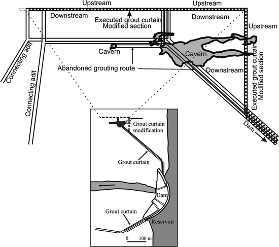
Salman Farsi Dam, Iran. Modification of grout curtain route due to large cavern at curtain route (Dolder et al. 2002)


6.2.2 Cut-Off (Diaphragm) Walls
In the case of empty or sediment-filled caverns and cavernous zones, with volumes of tens up to hundreds of cubic meters, the efficiency of conventional grouting is questionable. With these caverns, a cut-off (diaphragm) wall is the most effective means of creating a watertight structure. The most common types of cut-off technologies are:
-
1.
Mining method of an open-pit (trench) excavation between galleries if the structure is situated above the GWL
-
2.
Overlapping piles method that is very useful if the cut-off structure is below the GWL
The mining method, using a combination of trenches, galleries, and shafts, was used for cavern plugging at the Tarbela Dam in Pakistan. A large reinforced concrete cut-off wall was constructed at the underground Wulichong Dam in China to block two underground rivers, surrounding caverns, and a series of wide fissures. The concrete cut-off wall is 100.4 m high, 50–30 m long and 2.5 to 2 m thick. Loose and weak rocks behind the wall (28–35 m) was excavated and backfilled with concrete and finally consolidated by high pressure grouting to complete the sealing process (Milanović 2004).
In the case of Karun I Dam in Iran, a clay-filled fault zone allowed hydrogeologic connection between the saturated rock upstream of the grout curtain and a large karst spring (named Big Spring) downstream of dam site. In natural conditions, the average discharge of the Big Spring varied from 3 to 15 m3/s. The leakage through this zone was blocked by a concrete cut-off, exceeding 100 m in height and about 20–30 m in width. This structure is supported by grout curtain from all sides.
At the Khao Leam Dam, Thailand, solution channels between 0.2 and 10.0 m in diameter posed a problem that was rectified by constructing a cut-off wall of overlapping piles 762 mm in diameter. The piles were drilled and concreted from very close and fully pressure-lined galleries. The vertical distance between galleries was only 14 m. For the treatment of minor karst porosity (opening width of 5–200 mm), 300 mm diameter piles were constructed under water using the same overlapping method. The major karst cavities were plugged by applying the mining method (for more information on this method, see Milanović 2004). The surface area of cut-off at the dam foundation is 77,000 m2 and about 360,000 m2 in the right abutment (Bergado et al. 1984).
Different schemes for cut-off construction were performed at the Wolf Creek Dam in USA. Above the GWL, the primary elements (1.29 m diameter) were excavated to a depth of about 21.3 m and a borehole was cased with a 1.19 m diameter temporary steel casing. Excavation continued inside the casing down to a depth of 42.6 m. That section of the hole was cased with a 1.04 m diameter casing. After installation of the permanent casing (0.66 m diameter), the hole was filled with tremie concrete. During removal of the temporary casing, the space between the permanent casing and the wall was filled with cement grout mix (Fetzer 1979).
One of the longest cut-off diaphragm walls was constructed as part of the antiseepage structure at the Akkopru Reservoir, Turkey. The cut-off consisted of overlapped concrete piles (440 mm diameter) to prevent hydraulic connection between pervious alluvial/conglomerate sediments (reservoir bottom) and the highly karstified limestone which was protected by a blanket of heavily reinforced concrete (Fig. 3.4). Average depth of the cut-off wall is 20–40 m and length is 729 m. In areas with large caverns, a second row of cut-off walls was constructed.
6.2.3 Treatment of Karst – Cavern Plugging
The most frequent technical difficulty in karstified rock is the presence of a cavern along the grout curtain route. In this case, the cavern plugging or “treatment of karst” is necessary. In engineering terms, the meaning of “treatment of karst” is the geotechnical operation needed to block or reduce concentrated leakage from reservoir through the ponors and estavelles or to block or reduce the groundwater circulation along any karst singularity (channels or caverns) that cannot be treated by conventional grouting technology.
The caverns filled with clay (particularly soft clay) are very questionable for grouting, particularly in the case of caverns below the water table. This kind of cavern deposit is not a groutable media. In the case of Wujiangdu Dam (China), the special technology was applied to treat soft clay (see last paragraph in this section).
Prior to treatment of any accessible cave, speleological investigations are mandatory. Before plugging the cavern, the walls of the cavern should be cleaned and filled using self-compacting concrete (SCC), mortar or thick grout mix. Finally, the contact grouting of the interface between plug and the rock is necessary. During the construction of Keban Dam (Turkey), about 30 caverns were treated with this technique. One cavity, called the Crab Cavity, located 320 m below the crest level, was filled with 64,000 m3 of concrete and injected solids. However, the largest cavern, called Petek (Fig. 3.8) was discovered during the first reservoir filling. The short subvertical karst channel connected the reservoir with the cave resulting in water losses from the reservoir up to 26 m3/s. To fill the Petek Cave, one shaft 2.5 m in diameter and 13 boreholes of 14–17 in in diameter were drilled. About 605,000 m3 of limestone blocks, gravel, sand, and clay were used to fill the cave. After this treatment, the leakage decreased to ∼8 m3/s, a more acceptable level, considering the inflow from the Firat River to be 635 m3/s (Milanović 2004).

Keban Dam, Turkey. Petek cavern remediation (Božović et al. 1981)
For the treatment of six large cavern systems along the grout curtain of the Salman Farsi Dam site (Iran) (Fig 3.9), 3,125 m3 of SCC was used. Before filling, all caverns and channels were speleologicaly investigated and auxiliary shafts and access adits were excavated for concrete transport (Dolder et al. 2002).

Salman Farsi Dam. Treatment of the large cavernous system at the curtain route between two grouting galleries (From Dolder et al. 2002)
Concrete plugs were constructed to prevent leakage through the channels connected to the reservoir in Buško Blato (B-H). In another example, the channel of Honeycomb Cave, Tennessee River (USA), situated in reservoir upstream from the Guntersvil Dam, was blocked by a concrete plug. A karst channel between Krupac Ponor and Krupac Reservoir (Montenegro) was also successfully plugged. The large cavern was discovered at the Douglas Dam site (USA). The cave was investigated by a mining operation. After cleaning, the cavern was filled with 4,965 t of concrete through the large diameter borehole at the surface. To achieve watertightness of Khaobin Reservoir (Vietnam) 17,600 m3 of cavities were cleaned for the construction and concrete walls were built for 10.5 km (Skiba et al. 1992).
Treatment of channels below the water table, particularly channels with flowing water under pressure, requires a very complex treatment technology. Even with sophisticated treatment methods, the ability to reduce leakage is not assured. For instance, along the grout curtain route of the Lar Dam in Iran, a large cavern, 27 m high and 68 m wide, was discovered at a depth of 210 m below the riverbed. The volume of the cavern was determined to exceed 90,000 m3. Through 214 mm diameter boreholes from a gallery, the downstream section of the cavern was filled with about 28,000 m3 of gravel, with a grading 5–50 mm and 34,000 m3 of crushed rock. In spite of the extensive grouting and filling of caverns, the reservoir losses are still very high (Djalaly 1988).
Below the El Cajon Dam site in Honduras, several large karst caverns at depth of 176 m or deeper were discovered and had to be grouted under an extremely high pressure head. Some of them were filled with plastic clay. The washing out of the huge amount of clay and consolidation of plastic clay was difficult to control. To plug larger cavities, the following solids were inserted into the cavities using special pipe arrangements and 100 mm diameter boreholes: 8,000 wooden balls (7 cm diameter), 650 mortar balls (6 cm diameter), and 25,000 polyurethane bags (Guifarro et al. 1996).
Prior to plugging the cavernous system at the left bank of Canelles Dam site (Spain), the caves were speleologically investigated and clayey-silty material was removed above the water table. The conduit (17 m2) was plugged with an 11 m long concrete plug. To fill the cave system, 1,380 t of dry material was used. Deep concentrated flows, down to depths of 200 m, were sealed by using polyurethane foam and acryl asphalt-resin mixes (Milanović 2004).
Cavities 250 m below the Wujiangdu Dam site in China, down to the depth of about 250 m, were filled with soft and very soft clay. To prevent clay washing from caverns, the soft clay in the caverns was subjected to four actions: hydraulic fracturing, extrusion, consolidation, and chemical hardening (Zoumei and Pinshou 1986). For successful hydraulic fracturing, the empty space between the clay deposits and the cavern roof was filled with cement grout mix. As a consequence of the high grout pressure (up to 60 kg/cm2), the resistance of the clay fillings to water pressure was considerably increased.
7 Dams and Reservoirs in Evaporates
A number of dams are situated on evaporates and many of them have been affected by dissolution problems and failures. At least 30 dams in USA were affected by gypsum dissolution, some with catastrophic and tragic consequences. Because of dissolution of gypsum in the foundation of St. Francis Dam (California), the dam collapsed in 1928. The primary cause of failure was a landslide in the schists. However, leakage through the gypsum conglomerate could have contributed to weakening foundations before landslide impact. At the time, the collapse represented the greatest civil engineering failure in that country and killed over 450 people. After 12 years of dam operation, the McMilan Reservoir, (constructed in 1893) dried up. Failure of Quail Creek Dike (Utah) occurred in 1989. The seepage problems, after first filling, have hampered Carter Lake and Horsetooth Reservoirs (Pearson 1999). The proposed Magnum Dam site (Oklahoma) was abandoned because of intensive karstification of gypsum bedrock (Johnson 2008).
Numerous dams in different countries also have gypsum dissolution problems: Kamskaya Dam site and Bratsk Reservoir (Eastern Siberia, Russia); El Isiro (Venezuela); Alloz San Loren, Estremera, and San Juan Dam (Spain); Mosul Dam (Iraq); Huoshipo Reservoir (China); Poechos Dam (Peru); Yangmazhai and Mahuangtian Reservoirs (China); Baypazinsk Dam (Tajikistan); Tange-Duk Reservoir (Iran); and the Yerevan Dam (Armenia). Due to karstified gypsum and problems in its foundation, design modifications were required for the Casa de Piedra Dam (Argentina).
Salt rock has been detected in the foundation of Rogun and Nurek Dams (Tajikistan) and in the reservoir bank of Gotvand Dam (Iran). Because the salt is 160 times more soluble than gypsum (in flowing water, dissolution rates increase tremendously), this kind of rock will cause leakage problems and pollution of the reservoir water. At the Gotvand Reservoir, deterioration of water quality and slope stability are the key problems. The evaporate block is 2.5 km by 1 km in area and 150 m thick. Remediation work involved recontouring the reservoir bank with added surface protective measures and optimizing the operation of the reservoir. However, dissolution processes cannot be completely eliminated at the Gotvand Reservoir. The main task of remedial measures is to decrease the intensity of solution and to improve bank stability.
The Kamskaya Dam and Reservoir was constructed in 1954 on the Kama River (Russia). The dam is 21 m high and 2.5 km long and is situated on a complex lithology of argillites, sandstone, gypsum, limestone, dolomites, and anhydrites. To prevent leakage below the dam site, a horizontal impervious blanket was constructed with an accompanying vertical grout curtain installed along its upstream border (Fig. 3.10). Immediately after reservoir impounding, leakage through the dam foundation was registered. Due to dissolution and suffusion processes, the permeability greatly increased. During the period from 1956 till 1961, 11 suffusion collapses occurred in the vicinity of the reservoir. To improve the density of the existing cement-based grout mix, a chemical gel-forming solution (oxaloaluminosilicate) was developed and successfully used (Milanović 2004).

Kamskaya dam site. Geological cross-section perpendicular to the dam axis (Milanović 2006). Alevrolite is a form of siltstone
The Huoshipo Reservoir (Guizhou Province, China) is situated in the upper gypsum-bearing dolomite and lower dolomite interlayered with 48 strata of gypsum. The gypsum is mostly corroded in a honeycomb shape. During reservoir impounding, the seepage increased slowly to 237 l/s. This water discharges at Sand Spring, 400 m downstream from the dam. As a result of the solution process, collapses formed at the reservoir bed, and laminar filtration was replaced by conduit flow. Antiseepage remedial work consisted of double-liquid grouting to plug the karst conduits, and blanketing all exposed gypsum layers prevented contact of reservoir water with gypsum-bearing strata (Lu and Cooper 1997).
The embankment of the Mosul Dam (Iraq) (110 m high) is situated on Miocene, well-bedded, clayey and marly rocks, gypsum, anhydrite, and limestone. During the first partial filling of the reservoir (1986), the leakage through the dam site increased up to 1,400 l/s. The leakage paths were located at an average depth of 60–70 m. The dissolution intensity of gypsum ranges from 42 to 80 t/day (Guzina et al. 1991). To replace the volume of dissolving minerals, an extensive and permanent grouting procedure was applied, however, without success. Most probable solution will be the construction of the very large cut-off wall.
Specific catastrophic failure of San Juan Earth Dam (Spain) occurred during the first filling of the reservoir in 2001. The San Juan Reservoir, with a capacity of 850,000 m3, was situated on gypsiferous- mantled pediment deposits overlaying tertiary dispersive clay sediments (Gutierrez et al. 2003). The gypsum component was sand size particles, and due to their intensive dissolution, the pediment structure disintegrated, permeability increased and part of the dam collapsed. A 10 m deep breach in the dam sent a huge flood which covered a large part of the downstream area.
The region of the Bratsk Reservoir (Angara River, Russia) was well known as a karst environment. After the construction of the Bratsk Reservoir, many rapid collapses occurred in the areas with prevailing gypsum-anhydrite rocks. During reservoir filling (1963-1966), up to 200 sinkholes/km2 developed each year in the reservoir area, with damage to buildings and structures outside of the reservoir area as well (Trzhtsinsky 2002).
Gypsum in the foundations of the weir, locks, and powerhouse of the Hessigheim Dam on the River Neckar (Germany) dissolved and caused settlement problems. Sinkholes have also occurred near the dam, one hole being 8 m in diameter. During the remedial site investigation, cavities up to several meters in height were encountered in the boreholes. The underlying rock has now been grouted in an 8-year project (1986–1994) involving the use of about 10,600 t of cement. Further work still needs to be completed and the expected life of the remedial measures is 30–40 years (Cooper and Calow 1998).
8 Conclusions
The nature of karst presents a great variety of risks associated with any kind of human activities, particularly the high-risk nature of construction of large dams and reservoirs on karstified rocks. But dams are costly structures, and at the beginning, designers had little or no experience or knowledge related to karst. Conventional hydrogeological investigation methods and techniques were not successful in the case of karst-type porosity. In some cases, the empty reservoirs are a consequence of incorrect conclusions. Consequently, karst areas were avoided by dam designers.
In many cases, the karst regions are rich with hydro-related resources and their development depends on successful water management. In those regions, reclamation projects and construction of large dams and reservoirs have had a primary role in regional socioeconomic development.
During the past century, existing hydrogeological, hydrological, and geophysical investigation methods have developed or adapted to be efficient in the karst settings. Increasing of geotechnical knowledge and development of sealing technologies became one of key prerequisite for many successful dam construction projects. From the earliest days of dam/reservoir construction till today, finding the position of caverns and karst channels deep below the surface was and is still crucial. A fundamental geological understanding of karst and close cooperation of a wide spectrum of scientists and engineers is the basis of success. The final design of a grout curtain in karst can only be finalized during the execution phase. The curtain needs modifications and adaptations on the basis of the geological exploration of the underground. Newly developed sealing technologies (grouting techniques, underground flow plugging, surface impermeabilization of reservoir bottoms and others) have been successful in many recent projects.
However, the reservoirs in karst may fail to fill despite an extensive investigation program and sealing treatment. The risk cannot be totally eliminated by increasing the investigative programs, but it can be minimized to an acceptable level. In many cases, remedial works are necessary after the first filling of the reservoir. In other cases, progressive erosion of cavern filling and deterioration of grout curtains can take a long time (5-20 years). To control long-term processes, a complex monitoring program is the only way to prevent failure.
References
Altug S, Saticioglu Z (2001) Berke Arch Dam, Turkey: hydrogeology, karstification and treatment of limestone foundation. Technical documents in hydrogeology, vol 49. UNESCO, Paris, pp 315–323
Arandjelović D (1976) Geophysics in the karst. Geophysical Institute, Belgrade
Ballard RF, Cuenod Y, Jenni JP (1983) Detection of karst cavities by geophysical methods. Bull Eng Geol Environ 26–27(1):153–157. doi:10.1007/BF02594210
Beck BF (2004) Soil piping and sinkhole failures. In: Culver DC, White WB (eds.) Encyclopedia of caves. Elsevier, Amsterdam, pp 521–526
Bergado TD, Areepitak C, Prinzl F (1984) Foundation problems on karstic limestone formation in western Thailand. In: Beck BF (ed.) A case of Khao Laem Dam. Proceedings of the 1st multidisciplinary conference on sinkholes, Orlando, FL, pp 397–401
Bonacci O (1978) Karst hydrogeology. Springer, Berlin
Borić M (1980) The use of groundwater temperature changes in locating storage leakages in karst areas. 6th Yugoslav symposium on hydrogeology and engineering geology, Portorož, p 179
Božović A, Budanur H, Nonveiller E et al (1981) The Keban Dam foundation on karstified limestone: a case history. Bull Int Assoc Eng Geol 24:45–51
Bruce DA (2003) Sealing of massive water inflows through karst by grouting: principles and practice. In: Beck BF (ed.) Sinkholes and the engineering and environmental impacts of karst. Geotechnical special publication no.122. American Society of Civil Engineers, Reston, p 615
Chengjie Z (1988) A study of geothermal field and karstic leakage in karst area. Proceedings of the IAH 21st Congress, Geological Publishing House, Beijing, p 1127
Cooper AH, Calow RC (1998) Avoiding gypsum geohazards: guidance for planning and construction, British Geological Survey, Technical Report WC/98/5, UK NG125GG
Criss EM, Criss RE, Osburn GR (2008) Effects of stress on cave passage shape in karst terranes. Rock Mech Rock Eng 41(3):499–505
Deere DV (1976) Specific injection grout consumption. Dams and rock foundations: some design questions. Rock engineering for foundations and slopes conference II, Boulder, Colorado, p 55
Djalaly H (1988) Remedial and watertightening works of Lar Dam. Seizieme Congres das Grandes Barages, San Francisco
Dolder T, Kreuzer H, Milanović P (2002) Salman Farsi Dam project, Report on the Design of the Grout Curtain, Electrowatt-Ekono, Jaakko Poyry Group, Zurich, unpublished
Drogue C (1985) Geothermal gradients and groundwater circulation in fissured and karstic rocks. J Geodyn 4(1–4):219–231
Fazeli MA (2007) Construction of grout curtain in karstic environment case study: Salman Farsi Dam. Environ Geol 51:791–796. doi:10.1007/s00254-006-0397-8
Fetzer AC (1979) Wolf Creek Dam, engineering concepts, actions and results. Commission Internationale des Grandes Barrages, New Delhi, pp Q.59–R.5
Ford D, Williams P (2007) Karst hydrogeology and geomorphology. Wiley, England, pp 464–469
Giudici S (1999) Darwin Dam design and behavior of an embankment on karstic foundations. ICOLD, Antalia, pp 619–636
Guifarro R, Flores J, Kreuzer H (1996) Francisco Morozan Dam, Honduras: the successful extension of a grout curtain in karstic limestone. Int J Hydropower Dams 5(3):38–45
Gunay G, Arikan A, Bayari S, Ekmekci M (1985) Quantitative determination of bank storage in reservoirs constructed in karst areas: case study of Oymapinar Dam. IAHS Publication No. 161, Ankara
Gunay G, Milanović P (2007) Karst engineering studies at the Akkőprű reservoir area, southwest of Turkey. Environ Geol 51:781–785. doi:10.1007/s00254-006-0395-x
Gutierrez F, Desir G, Gutierrez M (2003) Causes of the catastrophic failure of an earth dam built on gypsiferous alluvium and dispersive clays (Altorricon, Huesca province, NE Spain). Environ Geol 43:842–851
Guzina B, Sarić M, Petrović N (1991) Seepage and dissolution at foundations of a dam during the first impounding of the reservoir. Congres des Grandes Barrages, Q66 Vienne, Austria, p 1459
Heitfeld KH (1965) Hydrogeological and engineering geological investigations on permeability of dam foundations in Sauerland. Germany Geol Mitt 5:210
Johnson KS (2008) Gypsum-karst problems in constructing dams in the USA. Environ Geol 53(5):945–950. doi:10.1007/s00254-007-0720-z
Kiernan K (1988) Human impacts and management responses in the karsts of Tasmania. Resources management in limestone landscape. Special publication no. 2. Department of Geography and Oceanography, University College, The Australian Defense Force Academy, Canberra, pp 69–92
Legchenko A, Ezersky M, Girard JF et al. (2008) Interpretation of magnetic resonance soundings in rocks with high electrical conductivity. J Appl Geophys 66(3–4):118–127
Lu Y (1986) Some problems of subsurface reservoirs constructed in karst regions of China. Institute of Hydrogeology and Engineering Geology, Beijing
Lu Y, Cooper AH (1997) Gypsum karst hazards in China. In: Beck BF, Stephenson JB (eds.) The engineering geology and hydrogeology of Karst Terranes. A. A. Balkema, Rotterdam, pp 117–126
Milanović P (1981) Karst hydrogeology. Water Resources Publication, Littleton
Milanović P (2000) Geological engineering in karst. Zebra Publishing, Belgrade
Milanović P (2001) The special problems of engineering in karst. In: Gunay G (ed.) Present state and future trends in karst studies. Technical documents in hydrology 49 (1). UNESCO, Paris, p 45
Milanović P (2004) Water resources engineering in karst. CRC, Boca Raton
Milanović P (2006) Karst of Eastern Herzegovina and Dubrovnik Littoral. ASOS, Belgrade
Milanović S (2005) Investigations of underground karst morphology in applied hydrogeology. Master thesis (in Serbian). University Belgrade, Faculty of Mining and Geology/Department of Hydrogeology, Belgrade
Milanović P (2010) Aeration zone in karst – properties and investigations advances in research in karst media. Environ Earth Sci 3:423–428. doi:10.1007/978-3-642-12486-0_65
Milanovic S, Stevanovic Z, Jemcov I (2010) Water losses risk assessment: an example from Carpathian karst. Environ Earth Sci 60(4):817–827. doi:10.1007/s12665-009-0219-x
Pavlin B (1970) Kruščica storage basin in the cavernous area, Dixieme Congres des Grandes Barages (ICOLD), Montreal, p 209
Pearson R (1999) Geology and safety of dams, case histories in gypsum karst for Horsetooth Dam and Carter Lake Dam no.2, Colorado, Bureau of reclamation, USBR Technical Service Center D-8321, Denver
Ravnik D, Rajver D (1998) The use of inverse geotherms for determining underground flow at the Ombla karst spring near Dubrovnik, Croatia. J Appl Geophys 39(3):177
Romanov D, Gabrovšek F, Dreybrodt W (2003) Dam sites in soluble rocks: a model of increasing leakage by dissolutional widening of fractures beneath a dam. Eng Geol 70:17–35
Sharp TM (1997) Mechanics of formation of cover collapse sinkholes. In: Beck BF, Stephenson JB (eds.) Engineering geology and hydrogeology of karst terranes. A. A. Balkema, Rotterdam, pp 29–36
Skiba SI, Molokov LA, Dobrin EZ (1992) Khoabin Dam on Da river (Vietnam): geology and dams. M Energoatonizdat 12:101–110
Trzhtsinsky YB (2002) Human-induced activation of gypsum karst in the southern Priangaria (East Siberia, Russia). Carbonates Evaporites 17(2):154–158. doi:10.1007/BF03176481
Yuan D (1999) The construction of underground dams on subterranean streams in South China Karst. Institute of Karst Geology, Guilin, p 62
Zoumei Z, Pinshou H (1986) Grouting of the karstic caves with clay fillings. Research Institute of Water Conservancy and Hydroelectric Power, Beijing
Author information
Authors and Affiliations
Corresponding author
Editor information
Editors and Affiliations
Rights and permissions
Copyright information
© 2011 Springer Science+Business Media B.V.
About this chapter
Cite this chapter
Milanović, P. (2011). Dams and Reservoirs in Karst. In: van Beynen, P. (eds) Karst Management. Springer, Dordrecht. https://doi.org/10.1007/978-94-007-1207-2_3
Download citation
DOI: https://doi.org/10.1007/978-94-007-1207-2_3
Published:
Publisher Name: Springer, Dordrecht
Print ISBN: 978-94-007-1206-5
Online ISBN: 978-94-007-1207-2
eBook Packages: Earth and Environmental ScienceEarth and Environmental Science (R0)