
Abstract
Multi Axis CnC gear manufacturing offers gear-makers the sort of versatility in tooth shape and tooling that no dedicated gear-cutting machine can offer, but that versatility usually comes at the expense of production volume. However, any gear-cutting machine, whether dedicated or CnC, is affected by build and wear errors that are transmitted to the workpiece. The same applies to the tools. Manufacturing errors on the tooth flank topography resulting from machining and tooling can be quite significant, and must therefore be controlled by Closed Loop. Commercially-available Computer Aided Manufacturing programs rely on a point cloud, such as IGES or STEP files, to describe the tooth flank topography. Despite being a very general approach, this method requires an external Tooth Flank Generator to create the point cloud, and therefore Closed Loop cannot be applied effectively. This document presents an integrated approach to Tooth Flank Generation, Closed Loop, and multi-axis CnC manufacturing of straight-bevel and spiral-bevel gears, in which a Unified Model is applied to different gear types. The Unified Model is used to calculate tooth flank topography, generate CMM target coordinates and use CMM output to minimize manufacturing errors. The machine settings describing tool and workpiece positions and movements in a gear-cutting machine, either before or after Closed Loop, are used to define equivalent positions and movements in a multi-axis CnC machine. Actual examples of gears cut and corrected on 5 Axis CnC machines show that the presented method is general, fast, and accurate.
Access provided by CONRICYT-eBooks. Download chapter PDF
Keywords
1 Introduction
Multi axis CnC gear manufacturing is fast becoming mainstream in the gear industry, as it offers gear-makers the versatility in tooth shape and tooling that no dedicated gear cutting machine can offer. The cost for this versatility is decreased output volume when compared to dedicated gear-cutting machines. However, in some instances, such as very large spiral-bevel gears , multi axis CnC machines may be the only option, since gear machine makers such as Gleason and Klingelnberg do not offer machines capable of cutting spiral-bevel gears beyond ~2 m in diameter. And for modules up to 3.5 mm, most 5 Axis CnC machines can easily cut spiral-bevel gears using Face Mill cutters, or Coniflex™ straight-bevel gears using dish-type cutters.
Any gear-cutting machine, whether dedicated or multi-axis CnC, is inherently affected by build and wear errors that are transmitted to the workpiece. The same applies to tools. Such manufacturing errors can be quite significant in the way they affect the kinematics of a gear set, and must therefore be controlled. The Closed Loop (i.e., Corrective Machine Settings), used to control such manufacturing errors, has been in use since the early 1980s [5] in dedicated spiral-bevel gear-cutting machines, and is therefore well known. It has been expanded to spur, helical, Beveloid, straight-bevel and Coniflex gears.
Commercially available Computer Aided Manufacturing programs mostly rely on a point cloud, such as IGES or STEP files, to describe tooth flank geometry. The selected tool is then guided by the user along the tooth flank to generate the part program driving the CnC machine. Despite being a very general approach, this method can be slow, is error prone, and requires an external Tooth Flank Generator to create the point cloud, such that Closed Loop cannot be applied effectively.
This document presents an integrated approach to Tooth Flank Generation, Closed Loop, and multi-axis CnC manufacturing of straight-bevel and spiral-bevel gears , in which a Unified Model for the simulation of gear manufacturing is applied to different gear types. The Unified Model is used to calculate tooth flank topography and generate target files that are fed into a CMM whose output is then used to determine new machine settings, minimizing the differences between the manufactured part and the design simulation. The Unified Model and the machine settings describing tool and workpiece positions and movements in a gear-cutting machine, either before or after Closed Loop , are used to define equivalent positions and movements in a multi-axis CnC machine.
2 The Tooth Flank Generator
A Tooth Flank Generator can be described as a group of software functions defining the shape of a tool and its movements relative to a workpiece and solving the resulting equations within the boundaries of a given blank. Since the vast majority of gears are generated, the generating process should be the basis of any Tooth Flank Generator.
The generating process [1] is based on the concept of a cutter blade representing one tooth of a theoretical generating gear meshing with the workpiece. The fundamental equation of meshing can be written as
Equation (1) states that, at any point, the relative speed vector of the contacting tool and workpiece surfaces must be in a plane perpendicular to their common normal.
When applied using the reference frames of Fig. 1, Eq. (1) yields an unbounded generated surface in the workpiece reference frame. The generated surface is a function of the machine settings and three variables, respectively, cutter position αc (angular or linear), work piece roll angle α3, and position S of a point along the edge of the cutter blade:

Reference frames for face milling simulation
The solution of Eq. (2) is a series of contact points between the cutter blade and the workpiece describing a line along the path of the cutter blade. The envelope of a series of such lines yields a generated tooth, as shown in Fig. 3. Equation (2) is solved numerically in real time.
The Tooth Flank Generator, which uses the Unified Model of Eq. (3), includes work and tool adjustments and movements found in gear-cutting machines. In CnC controlled machines, machine settings can be continuously altered during generation, thus allowing for significant improvements in the kinematics of gear sets.
Figure 1 below represents the most general case in the simulation of cutting processes, and is therefore the basis for the Unified Model of the Tooth Flank Generator. The implicit equation of the general tooth surface is
Vector \( \vec{D} \) in Eq. (4) is the position of a point along a Face Mill cutter blade. In Eq. (3), vector \( \vec{D} \) is rotated by cutter phase angle \( \upalpha_{\text{c}} \), tilt angle \( \tau \) and swivel angle J, translated to the origin of the machine by vector R, rotated by cradle angle L 1m and root angle Γ, translated to the origin of the workpiece by vector P, rotated by roll angle α3 and finally rotated by R c , the Face-Hobbing-cutter-to-work-piece timing relationship (when applicable). Figure 2 shows the general definition of a Face Mill cutter blade (Fig. 3).

Face mill cutter reference frame

Generated tooth
Similarly, Eq. (5) defines vector \( \vec{N} \), the normal vector to the cutter blade at point S, and Eq. (6) gives the transformations required between the reference frames of the cutter blade and the work piece, from which translations R and P have been omitted.
In Eqs. (3) and (6), rotations and translations can be expanded into Taylor series to allow for higher order manufacturing flexibility on CnC controlled machines.
For straight-bevel gears cut by a 2-tool generator, the terms involving cutter tilt \( \tau \), cutter swivel J and Face Hobbing rotation R c are dropped from Eqs. (3) and (6), and cutter phase angle αc becomes a translation of the tool. For Coniflex™ gears, the terms involving cutter swivel J and Face Hobbing rotation R c are dropped from Eqs. (3) and (6).
3 Calibration of the Tooth Flank Generator
Fundamentally, the Tooth Flank Generator is aimed at digitally reproducing the same tooth surfaces as would be cut on an actual machine. It is therefore important to establish the exactness of the simulation such that one can assume that the tool movements in a CnC machine will replicate the desired tooth surface independently of the tool used.
In order to calibrate the Tooth Flank Generator, its output must be compared to something reliable and universally accepted in the industry. For this purpose, two sources stand out for spiral-bevel gears: The Gleason Works and Klingelnberg GmbH, the world leaders in spiral-bevel gear manufacturing technology.
3.1 Comparison with Gleason’s CAGE
The output of the Tooth Flank Generator described in the previous section is compared to the CMM Nominal obtained from Gleason’s CAGE software.
Using the Basic machine settings for an 8 × 39 Face Milled spiral-bevel pinion, Fig. 4 below shows the differences between the CAGE simulation (red lines for the OB, blue lines for the IB) and the simulation based on the presented Tooth Flank Generator (black lines). Except for two points at the heel at the bottom of the OB and IB flanks of the tooth (upper and lower right corners), the Tooth Flank Generator output is identical to that of CAGE within 0.0002 mm.

Comparison with CAGE—8 × 37 face milled spiral-bevel pinion
3.2 Comparison with Klingelnberg’s KiMOS
The output of the Tooth Flank Generator described in the previous section is compared to the CMM Nominal obtained from Klingelnberg’s KIMoS software.
Using the same Basic machine settings as for the above 8 × 39 Face Milled spiral-bevel pinion, Fig. 5 below shows the differences between the KIMoS simulation (red lines for the OB, blue lines for the IB) and the simulation based on the presented Tooth Flank Generator (black lines). The deviations noted with Gleason’s CAGE near the fillet at the heel have disappeared, and the Tooth Flank Generator output is identical to KIMoS’ output within 0.0002 mm.

Comparison with KIMoS—8 × 37 face milled spiral-bevel pinion
4 Closed Loop
The Closed Loop , an essential part of any gear manufacturing software, calculates changes in machine settings to remove surface errors caused by machine and tool, and matches the manufactured tooth surface to the designed tooth surface [2,3,4].
The following surface errors are generally considered adequate to describe the quality of a tooth flank and are used in the Closed Loop. Average surface errors are calculated as follows:
-
Pressure angle error:
$$ \Phi = \frac{{\sum\nolimits_{col = 1}^{j} {\frac{{\left[ {\sum\nolimits_{row = 1}^{i} {\frac{{\varepsilon_{i,j} - \varepsilon_{1,j} }}{{y_{i,j} - y_{1,j} }}} } \right]}}{i}} }}{j}; $$(7) -
Spiral angle error:
$$ \Psi = \frac{{\sum\nolimits_{row = 1}^{i} {\frac{{\left[ {\sum\nolimits_{col = 1}^{j} {\frac{{\varepsilon_{i,j} - \varepsilon_{i,1} }}{{x_{i,j} - x_{i,1} }}} } \right]}}{j}} }}{i}; $$(8) -
Lengthwise crowning error:
$$ \Xi = \frac{{\sum\nolimits_{row = 1}^{i} {\frac{{(2\varepsilon_{i,mid} - (\varepsilon_{i,1} + \varepsilon_{i,j} ))}}{2}} }}{i}; $$(9) -
Bias error:
$$ \zeta =\Phi _{1} -\Phi _{j} ; $$(10) -
Profile curvature error:
$$ \xi = \frac{{\sum\nolimits_{col = 1}^{j} {\frac{{(2\varepsilon_{mid,j} - (\varepsilon_{1,j} + \varepsilon_{i,j} ))}}{2}} }}{j}; $$(11)
where
-
i is the index of row data along the face width,
-
j is the index of column data depthwise,
-
mid is the index of the mid-column or mid-row data,
-
ε i,j is the error value at point ij of the measurement grid,
-
x i,j is the distance between points along the face width,
-
y i,j is the distance between measurement points depthwise.
Surface Matching, the algorithm used in Closed Loop , is based on the response of the error surface, i.e., the difference between the simulated and measured tooth surfaces (Fig. 6) to changes in selected machine settings. Sensitivity factors are obtained by changing machine settings, recalculating the error surface and solving Eqs. (7)–(11).

Error surface
In the Surface Matching algorithm, a combination of machine settings is sought such that the theoretical surface matches the measured surface. To achieve this, the following objective functions are to be satisfied:
where
-
mi are the considered machine settings,
-
Φ and Ψ are the averaged pressure and spiral angle errors,
-
Ξ and ζ are the lengthwise crowning and bias error values,
-
ξ is the profile curvature error,
-
Ti are target surface deviations,
-
Li are the tolerances within which the objective functions can be considered satisfied.
A Newton-Raphson-based solution is used to solve the above functions. The solution yields new settings for a dedicated machine, which are converted to a 5 Axis CnC machine.
5 Tools Used in CnC Gear Manufacturing
Thanks to the flexibility in movement and tool orientation offered by multi-axis CnC machines, virtually any tool type can be used to cut gears . The most frequently found tools are:
-
Face Mill cutter,
-
Coniflex™ dish type cutter,
-
Conical Side Milling Tool, or CoSIMT for short,
-
End Mill,
-
Ball Mill.
Other tools are also used in applications such as Skiving for internal gears and splines, but are not used for straight or spiral-bevel gears, and therefore will not be considered here.
5.1 Face Mill Cutter
Face Mill cutters used to cut spiral-bevel gears in multi-axis CnC machines are no different from those used in dedicated spiral-bevel gear-cutting machines, with the exception of the chucking head, for which a special adapter may be required.
Cutters up to ~7.5″ diameter can be used on an average multi-axis CnC machine. Beyond 7.5″ diameter, power and stiffness requirements may not be satisfied, which limits the gear module that can be cut on a normal multi-axis CnC machine with a Face Mill cutter.
Face Mill cutters come in three basic embodiments:
-
(i)
with solid blades (Fig. 7) for which no adjustment is possible; this is usually found on small diameter cutters;
Fig. 7 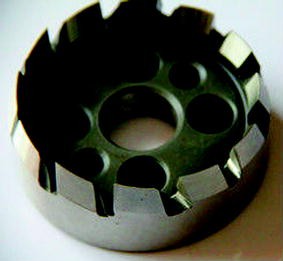
Solid face mill cutter (Photo courtesy Harbin Tool Works)
-
(ii)
with detachable blades (Fig. 8) for grinding and radial adjustment; usually found in medium to large size cutters;
Fig. 8 
Face mill cutter with detachable blades (Photo courtesy Weiku.com)
-
(iii)
with replaceable inserts (Fig. 9) for which no adjustment is possible; this is an economical solution for roughing prior to heat treatment and finish grinding, since the inserts are rather inexpensive when compared to roughing with a cutter with detachable blades, or to solid grinding for which grinding wheels are expensive, need to be dressed and wear out rapidly.
Fig. 9 
Face mill cutter with replaceable inserts (Photo courtesy Sandvik Coromant)


In cases (i) and (ii) above, blades need to be sharpened at given intervals. Case (iii) requires the inserts to be changed when needed.
The basic geometry of a Face Mill cutter is described in Fig. 10 below, in which the cutting edge of the blade can be straight or circular. The Average Diameter is given at the center of the Point Width and denotes a cutter used in completing cycles, such as Spread Blade™, Duplex Helical™ and Formate™.

Basic face mill cutter
Figure 11 below shows a variant of the basic Face Mill cutter, but with TopRem™, in which a section of the blade has a different angle in order to create a protuberance at the bottom of the tooth. A protuberance is often to be desired for the purpose of preventing tool contact with the fillet at the finishing operation after heat treatment, and also applies just as much to grinding as to lapping.

Face mill cutter with TopRem™
Cutting cycles such as Fixed Setting™ and Modified Roll™ usually require one roughing cutter, such as the Basic Face Mill cutter in Fig. 10, and two finishing cutters (Fig. 12), one for the Convex flank (I.B.) and one for the Concave flank (O.B.), for which the machine settings are usually different.

Fixed setting cutter with TopRem™
5.2 Coniflex™ Dish Type Cutter
Coniflex™ cutters (Fig. 13) are used to cut straight-bevel gears with lengthwise crowning. These are available either in solid form (Fig. 13) or with replaceable blades that can be ground. While cutting cycles are short, Coniflex cutters quickly grow in diameter with the module. Available in sizes of 4.25″, 9″ and 15″, only the smaller variant of 4.25″ diameter is really practical on multi-axis CnC machines because of power requirements and weight considerations when the diameter reaches 9″ and above.

Coniflex™ cutters (Photo courtesy The Gleason Works)
The original, mechanical Coniflex™ machines from the Gleason Works use two interlocking cutters (Fig. 14), such that both the left and right tooth flanks are cut simultaneously. In multi-axis CnC cutting, only one cutter can be used at any given time, and therefore the left and right tooth flanks are cut in two separate cycles. While this cutting cycle may appear to be somewhat slower than that of the conventional mechanical machine, cutter tilt can be modified freely in CnC machines and thus offers more flexibility in the design of Coniflex gear sets.

Coniflex™ cutters (Photo courtesy Arrow Gear)
5.3 Conical Side Milling Tool (CoSIMT)
A Conical Side Milling Tool, or CoSIMT, is a milling tool of variable shape. It can be found either with solid blades (Fig. 15) or with replaceable inserts. CoSIMT tools typically have high feed rates, and are thus well-suited to gear milling. The initial tool cost of the CoSIMT body is easily offset by the superior output.

CoroMill 327 CoSIMT (Photo courtesy Sandvik Coromant)
CoSIMT tools can be used to cut any tooth shape with a convex profile curvature. This therefore excludes Face Gears for which the profile curvature is concave.
CoSIMT are offered in various shapes and sizes. Figure 16 shows the general definition of a CoSIMT, for which the Outside Angle can be positive, null or negative, which results in the tools shown in Fig. 17. The Inside cutting edge is on the same side as the arbor.

CoSIMT general definition (Photo courtesy Involute Simulation Softwares)

a Positive outside angle, b null outside angle and c negative outside angle
-
When the Outside Angle is positive, both the Outside and Inside cutting edges are on a Convex cone, which results in a single contact point between the tool and the work piece in the lengthwise direction; thus, it is good if the lengthwise curvature is concave, such as the OB side of spiral-bevel gears.
-
When the Outside Angle is null, the Outside cutting edge is a plane, and therefore offers advantageous cutting conditions for straight-bevel , spur and helical gears with no lengthwise crowning.
-
When the Outside Angle is negative, a Concave cone results, and the tool can now be used to cut gear teeth with a convex lengthwise curvature, such as Coniflex and the IB side of spiral-bevel gears.
Theoretically, the cutting edges could also be curved, as shown in the upper right corner of Fig. 16. Although not yet offered on the market, curved blades would allow for a cost-effective generation of Face Gear teeth in which the profile curvature is concave, whereas the current option is to use Ball Mill tools that are much slower.
5.4 End Mill Tools
End Mill tools present a shape similar to that of a drill bit (Fig. 18), except that they are designed to cut with their side flukes. Depending on the End Mill diameter, the depth of cut, whether the removed material is a slot or a profile, and the type and hardness of the material, feed rates in steel vary from less than 100 mm/min for the smaller diameters to more than 1500 mm/min for the larger diameters.

End mill tools
Two significant advantages of End Mill tools are their wide range of dimensions and comparatively low cost. Major disadvantages include their high wear and slow feed rates for small diameter tools, which is often the case when cutting gears of small to medium size modules for which slot width is limited to less than 6 mm.
End Mill tools can be broadly classified as follows (Fig. 19):

a Square end mill, b bull nose end mill and c ball nose end mill
-
Square: no edge radius; normally a small break-edge; used to open a tooth flank gap (roughing operation) or to finish cutting the tooth flank;
-
Bull Nose: edge radius less than ½ the End Mill diameter; used to open the gap in the fillet (roughing operation), or to finish cut the fillet;
-
Ball Nose: edge radius equal to ½ the End Mill diameter; used to open the gap in the fillet (roughing operation), or to finish cut the fillet.
5.5 Ball Mill Tools
Ball Mill tools present a shape with a sphere at the cutting end (Fig. 20), usually followed by a contraction, a tapered section and a stem of constant diameter. Only the sphere end is meant to cut.

Ball mill tool
Functionally speaking, Ball Mill and Ball Nose tools are interchangeable when cutting a tooth fillet, since only the spherical end of the End Mill tool is used. The Ball Mill tool (Fig. 21) has the advantage of a slight contraction between the cutting sphere and the tapered section leading to the stem, which allows for introducing a protuberance, i.e., negative stock, into the fillet without damaging the tooth profile, whereas the straight section of a Ball Nose tool immediately above the spherical end may remove some material on the profile if negative stock is important.

Ball mill tool
The contraction above the cutting sphere of a Ball Mill tool also introduces a weakness because of the reduced section, and thus feed rate and cutting depth may have to be reduced.
Similarly to End Mill tools, Ball Mill tools are available in a wide range of dimensions at comparatively low cost. Major disadvantages include their high wear and slow feed rates for small diameter tools, which is often the case when cutting gears of small to medium size modules for which slot width is limited to less than 6 mm. Ball Mill tools also tend to cut in the same area of the sphere when finishing a tooth flank, thus accelerating wear.
6 Conversion from Dedicated to CnC Machine
Figure 22 below shows a Face Mill cutter in a dedicated machine. In the approach proposed here, the Face Mill cutter is replaced by another tool (such as a Conical Side Milling Tool, i.e., CoSIMT), which is forced to follow the path of one cutter blade of the Face Mill cutter (Fig. 23). This approach is extended to Coniflex , End Mill and Ball Mill tools, and readily lends itself to the use of Closed Loop described above.

Ref. cutter and work piece relative position

Ref. cutter and CoSIMT
The conversion from a conventional gear-cutting machine to a multi-axis CnC machine is based on two conditions:
-
(i)
Maintaining the location of the tool in relation to the origin of the reference frame attached to the workpiece, and
-
(ii)
Maintaining the relative orientation and phase angle between the axis of the tool and that of the workpiece (Fig. 22).
Referring to Eq. (3), the position of the center point of a Face Mill cutter, in the workpiece reference frame, is given as
Referring to Eq. (6), the orientation of the axis of a Face Mill cutter, in the workpiece reference frame, is given as
The axis of rotation of the workpiece being
Angle \( \Lambda \) between the axis of the cutter and that of the workpiece is therefore
Multi-axis CnC lathes and milling machines can come in different architectures, as explained in the following section. All 5 axis architectures can accommodate any angle Λ between the axis of the tool and the workpiece.
Tools include dish-type cutters for Coniflex™ straight-bevel gears , Face Mill cutters compatible with the CnC machine size, and Conical Side Milling Tool cutters (or CoSIMT), such as Sandvik’s InvoMill, End Mill and Ball Mill tools. Basically, End Mill, Ball Mill and CoSIMT tools can cut any tooth shape, including Face Hobbed gears. Each tool type requires a specific definition for Eqs. (17) and (18) in order to calculate angle Λ in Eq. (20).
7 CnC Machine Architectures
5 Axis CnC machines found in the market comprise three main architectures, as described below. Machines are offered with a variety of controllers, which allow the CnC machine manufacturer to define the names and signs of all the axes (i.e., rename the axes as desired). The coordinates in part programs fed to the controller can be given as:
-
(i)
Machine coordinates, i.e., in a fixed reference frame attached to the machine body; angles A, B and C are used to tilt the turntable, pivot the machine head, and rotate the workpiece;
-
(ii)
Workpiece coordinates, i.e., in a reference frame rotating with the workpiece with a zero along the axis of rotation, such as the pitch apex of bevel gears; angles A, B and C are used to tilt the turntable, pivot the machine head, and rotate the workpiece;
-
(iii)
Workpiece coordinates and tool unit vector, i.e., as in (ii) above for the linear axes; however, a unit vector gives the orientation of the tool axis which the controller converts into angles A, B and C to tilt the turntable, pivot the machine head, and rotate the workpiece.
7.1 Tilting Turntable
The turntable (Fig. 24) on which the workpiece is installed can both rotate by angle C about its axis of symmetry and tilt by angle A about axis X. The machine head/turntable can be translated along axes X, Y and Z.

Tilting turntable 5 axis CnC machine
This machine type is well-adapted to small workpieces with short shafts. When the parts become large, weight considerations become predominant and tilting precision suffers. Turntable tilt angle A is usually limited around ±100°.
7.2 Pivoting Tool Head
The turntable (Fig. 25) on which the work piece is installed is fixed in orientation and rotates by angle C about axis Z; the tool head pivots by angle B about axis Y. The machine head/turntable can be translated along axes X, Y and Z. Tool pivot angle B is usually limited around ±100°.

Pivoting tool head 5 axis CnC machine
This machine type is well adapted to cutting pinions on long shafts when embodied as a lathe. In lathes, the OD of the part is limited by the travel of the head in the radial direction. Also, machine head pivot is only allowed in one direction when a short shaft work piece is mounted directly on the turntable to prevent collisions. The axis of the turntable can also be vertical, and in this case, is well-suited to cutting large bevel gears on short shafts.
7.3 Tilting and Swiveling Tool Head
The turntable (Fig. 26) on which the workpiece is installed is fixed; the tool head tilts by angle B about axis Y and swivels by angle A about axis X. The machine head can be translated along axes X, Y and Z. Turntable rotation is used solely for indexing.

Tilting and swiveling tool head 5 axis CnC machine
This machine type is well-adapted to cutting bevel gears of large diameter. Indexing precision is affected by the weight of the workpiece. The overhung machine head can be an issue with heavy tools.
8 Cutting Cycles with Multi Axis CnC Machines
Given the different tool types and shapes described above, different cutting cycles are to be expected in order to offer flexibility and allow for cycle optimization. Several cutting cycle possibilities are presented below for each tool type.
8.1 Face Milling Cutter
Spiral-bevel gears can be either generated (with or without helical motion and modified roll) or non-generated, i.e., Formate™ cut.
Basically, the cutting cycle of a generated spiral-bevel workpiece involves (Fig. 27):

Single-roll external plunge
-
Plunging the tool to a given depth, at Toe or Heel,
-
Generating the part, either in an up-roll or down-roll direction,
-
Retracting the tool above the blank and returning the tool to its plunging position,
-
Indexing the workpiece to cut the next tooth gap.
Single-roll or double-roll can also be desired; single-roll (Fig. 27) implies that, after plunging the tool, the part is generated either in an up-roll or down-roll direction, at the end of which the tool is retracted (dotted line) and returned to its starting location, and the cycle recommences for the next tooth gap.
In double-roll (Fig. 28), the tool is plunged to a set in position, i.e., before full depth, and the part is generated in one direction, either up-roll or down-roll; at the end of the rolling motion, the tool is plunged full depth and returns to the starting end of the tooth gap while generating. The tool is then retracted (dotted line) and the cycle recommences for the next tooth gap.

Double-roll external plunge
Several factors can affect tooth flank quality and cycle time:
-
Height to which the tool is retracted above the blank;
-
Whether the tool is plunged full speed outside the blank (outside Toe in Fig. 27) and rolling then begins, or the tool is plunged at a lower feed rate at the very beginning of the rolling motion (at Toe in Fig. 29) i.e., in the tooth itself;
Fig. 29 
Single-roll internal plunge
-
How many tooth gaps are skipped when indexing, such as to spread tool wear, heat generation and indexing errors around the part.

For non-generated gears , basically a simple plunge cut is needed. The cycle can also be used to rough generated parts, but without generation.
8.2 Coniflex™ Cutter
Coniflex bevel gears can be cut using dish-type cutters such as those shown in Figs. 13 and 14. Coniflex bevel gears are always generated.
On a multi-axis CnC machine, the cutting cycle involves (Fig. 30):

Coniflex cycle on a 5 axis CnC machine
-
Plunging the tool from a position above the blank (1),
-
Rolling one tooth flank (2),
-
Retracting the tool (3),
-
Indexing the part and recommencing the cycle until all the tooth flanks on one side of the teeth have been generated;
-
and subsequently withdrawing the tool (4) beyond the apex of the part and moving it to the opposite side of the workpiece (5) where the other tooth flanks are generated in the same manner.
8.3 CoSIMT, End Mill and Ball Mill Tools
These tools share similarities that allow us to treat them as a group. Specifics will be noted in the text when required.
Generally speaking, cutting cycles involve either moving the tool along the face width, or in the depthwise direction. It is also advantageous to consider the tooth flank and the fillet separately in order to use the most appropriate tool for each.
-
Along the face width: each time the tool reaches the end of the tooth, it is stepped down progressively from the tooth tip to the fillet (Fig. 31); when the bottom is reached, the tool is retracted and returned to the starting position to cut another tooth flank; this can be inversed, starting at the tooth bottom and finishing at the tooth tip.
Fig. 31 
Cutting along the face width
-
Depthwise direction: the tool follows the tooth flank from tip to fillet (Fig. 32); the cycle can then advance the tool along the face width and backtrack from the fillet to the tip along the tooth profile; or else, the tool is retracted, advanced along the face width, and the cycle starts again from the tooth tip to the fillet.
Fig. 32 
Cutting depth wise


Cutting depthwise is especially well-adapted to CoSIMT tools that have a flat face, as depicted in Fig. 32, where, in this case, the Inside Blade angle is null.
However, scalloping will occur along the face width near the bottom of the teeth, as shown in Fig. 33, and one or more tool passes along the face width may be required to ensure a smooth finish near the fillet.

Scalloping when cutting depth wise
-
In the fillet: given that the tool must be spherical to cut the fillet, a cutting cycle along the face width gives the best results. This usually implies Ball Nose or Ball Mill tools whose radius is less than that of the fillet, thus possessing a slow feed rate. A faster approach is to use a CoSIMT tool (Fig. 34) with a feed rate several times that of a Ball Nose or Ball Mill tool.
Fig. 34 
Fillet finishing with a CoSIMT tool

Let us now consider the End Mill tool shown in Fig. 35, in several cutting positions along the profile of a spur gear tooth (this will make things easier to visualize): it is clear that scallops will be left on the profile because of the limited number of tool positions. Knowing the equation of the tooth surface, provided by the Tooth Flank Generator, allows for calculating the height of the scallop and optimizing the cycle for surface quality versus consumed time.

End mill tool and tooth profile scalloping
When a Ball Mill is used, as in Fig. 36, scallop height will be much larger if the depthwise step is the same as for an End Mill, which implies a greater number of—and more closely spaced—depthwise tool passes to achieve the desired tooth surface quality. Cycle time can be as much as 10 times more than for an End Mill to achieve the same surface quality.

Ball mill tool and tooth profile scalloping
To cut the tooth flank, it is therefore desirable to use a tool with a straight cutting edge or, if available, a concave cutting edge, rather than a tool with a convex cutting edge such as a Ball Mill. CoSIMT and End Mill tools fall into this category.
9 Applications
The following examples demonstrate the effectiveness of the methods presented above using different gear geometries, tools, and 5 Axis CnC machines. Closed Loop , while possible with commercial CAM software based on clouds of points, such as STEP files, describing the tooth surfaces, is much slower and does not offer the same effectiveness as that based on a Tooth Flank Generator (as presented above).
9.1 Application 1: 32 Tooth, 1.25 mm Module, Coniflex Pinion; Dish-Type Cutter
This pinion was cut on a tilting turntable type 5 Axis CnC machine. The first cut yielded the results shown in Fig. 37. Helix (fb) and pressure (fa) angle errors are visible on both tooth flanks (Table 1).

Error surface after 1st cut
Figure 38 shows the same part after the 1st Closed Loop iteration, where pressure and helix angle errors have all but disappeared (Table 2).

Error surface after correction
9.2 Application 2: 26 Tooth, 1.5 mm Module, Duplex Helical Spiral-Bevel Pinion
This pinion was cut on a tilting turntable type 5 Axis CnC machine using a 2″ Face Mill cutter. The 1st cut yielded the results shown in Fig. 39. Pressure (fa), spiral (fb) angle and bias errors are visible.

Error surface after 1st cut
Figure 40 shows the error surface after the 1st Closed Loop iteration. Clearly, pressure, spiral and bias errors have been corrected.

Error surface after correction
9.3 Application 3: 28 Tooth, 12.68 mm Module, Duplex Helical Spiral-Bevel Gear
This gear was cut on a tilting turntable type 5 Axis CnC machine using a 160 mm diameter Conical Side Milling Tool (CoSIMT). The 1st cut yielded the results shown in Fig. 41. Slight pressure angle errors (fa) are visible; the spiral angle error (fb) is close to zero; some lengthwise crowning is present on the Concave flank, some bias is visible on both tooth flanks, and thickness error is significant at +0.1031 mm (see Table 3).

Error surface after 1st cut
The results shown in Fig. 42 are obtained after the 1st correction. Table 4 lists the residual errors. The initial pressure angle and bias (warp) errors have disappeared.

Error surface after correction
However, since both tooth flanks are cut simultaneously in the Duplex Helical process, correcting bias can introduce some lengthwise crowning, as is visible in Table 4.
9.4 Application 4: 39 Tooth, 1.15 mm Module, Duplex Helical Generated Spiral-Bevel Gear Electrode
The copper electrode (Fig. 43) was cut on a tilting turntable type 5 Axis CnC machine using a 1.0 mm diameter End Mill tool for the flanks and a 0.8 mm diameter Ball Mill tool for the fillets. The 1st cut yielded the results shown in Fig. 44, in which virtually no error can be seen. Closed Loop is therefore not required here.

Generated spiral-bevel gear electrode

Error surface at 1st cut
When cutting copper, a comparatively soft material, tools do not wear at the same rate as when cutting steel. Given that the machine used was new and of a very high quality, and that the tools were within the advertised dimensions, the excellent results shown in Fig. 44 are not surprising.
9.5 Application 5: 38 Tooth, 1.348 mm Module, Straight-Bevel Gear Electrode
The copper electrode (Fig. 45) was cut on a tilting turntable type 5 Axis CnC machine using a 1.0 mm diameter End Mill tool for the flanks and a 0.8 mm diameter Ball Mill tool for the fillets. The 1st cut yielded the results shown in Fig. 46, in which virtually no error can be seen. Again, Closed Loop is not required.

Straight-bevel gear copper electrode

Error surface at 1st cut
10 Conclusions
The methods presented in the previous sections describe a system for simulating gear manufacturing processes, controlling manufacturing through Closed Loop (i.e., Corrective Machine Settings), and using the manufacturing capabilities of multi-axis CnC machines.
In practice, the presented Tooth Flank Generator and Closed Loop have been in industrial use for more than two decades, and have proven effective and reliable. Multi-axis CnC manufacturing has been in industrial use for several years and has allowed for the production of now countless gear sets.
Multi-axis CnC gear manufacturing allows for cutting quality gears on machines that can also be put to other uses. Tooling is flexible, and any tooth flank topography can be addressed through the presented methodology. The combination of the presented Tooth Flank Generator, coupled to Closed Loop, ensures manufacturers of a quality production.
References
Gosselin, C., Thomas, J.: A unified approach to the simulation of gear manufacturing and operation. International Conference on Gears. T.U.M., Munich, 7–9 Oct 2013
Gosselin, C., Thomas, J.: Integrated closed loop in 5 Axis CnC gear manufacturing. International Conference on Gear Production 2015. T.U.M., Munich, 5–6 Oct 2015
Gosselin, C., Shiono, Y., Kagimoto, H., Aoyama, N.: Corrective machine settings of spiral bevel and hypoid gears with profile deviations. World Congress on Gearing, Paris, 16–18 Mar 1999
Gosselin, C., Nonaka, T., Shiono, Y., Kubo, A., Tatsuno, T.: Identification of the machine settings of real hypoid gear tooth surfaces. ASME J. Mech. Des. 120 (1998)
Krenzer, T.J.: Computer aided corrective machine settings for manufacturing bevel and hypoid gear sets. AGMA Paper 84-FTM-4, Oct 1984
Acknowledgements
Fixed Setting, Modified Roll, Duplex Helical, Spread Blade, Formate, Coniflex, TopRem are all Trade Marks of The Gleason Works, Rochester, NY, USA.
Author information
Authors and Affiliations
Corresponding author
Editor information
Editors and Affiliations
Rights and permissions
Copyright information
© 2018 Springer International Publishing Switzerland
About this chapter
Cite this chapter
Gosselin, C. (2018). Multi Axis CnC Manufacturing of Straight and Spiral Bevel Gears. In: Goldfarb, V., Trubachev, E., Barmina, N. (eds) Advanced Gear Engineering. Mechanisms and Machine Science, vol 51. Springer, Cham. https://doi.org/10.1007/978-3-319-60399-5_8
Download citation
DOI: https://doi.org/10.1007/978-3-319-60399-5_8
Published:
Publisher Name: Springer, Cham
Print ISBN: 978-3-319-60398-8
Online ISBN: 978-3-319-60399-5
eBook Packages: EngineeringEngineering (R0)