
Abstract
As discussed in Chap. 7, the overall experience with the in-flight simulator HFB 320 operation was very positive. However, some limitations were encountered in its operation, mainly due to low payload, limited space for test equipment and crew, limited power supply, and high engine noise.
The original version of this chapter was revised: Author biography has been corrected. The erratum to this chapter is available at 10.1007/978-3-319-53997-3_14
An erratum to this chapter can be found at http://dx.doi.org/10.1007/978-3-319-53997-3_14
Access provided by CONRICYT-eBooks. Download chapter PDF
Keywords
These keywords were added by machine and not by the authors. This process is experimental and the keywords may be updated as the learning algorithm improves.
With contributions from 14 further coauthors

9.1 Modification and Equipment of Flight Test Vehicle
Dietrich Hanke
With contributions from Hartmut Griem and Hermann Hofer
9.1.1 Introduction and Project Definition Phase
As discussed in Chap. 7, the overall experience with the in-flight simulator HFB 320 operation was very positive. However, some limitations were encountered in its operation, mainly due to low payload, limited space for test equipment and crew, limited power supply, and high engine noise. Therefore, starting from 1977 the possibilities of higher-performance and efficient successor were explored. Technical requirements, covering a wide range of research applications and in-flight simulation, were then specified in the requirements catalog and formulated as a framework requirement for such a flight test vehicle [1].
The range of application covered the following research tasks: (1) Digital flight control, (2) Flying qualities and in-flight simulation, (3) Flight guidance and air traffic management, (4) Man-machine interfaces, (5) Modeling of aircraft and systems, and (6) Navigation and communication. In addition, the test vehicle was to serve as a test platform for system components such as sensors, antennas, actuators, avionics and navigation systems, data link systems, computer systems, operating elements, and display systems. Appropriate installation options and data interfaces were to be provided.
The aircraft was to have an electrical flight control system with high onboard computing power for experiments. In addition to a direct lift control, a direct lateral force control was also required, with the aim of enabling a complete six degrees-of-freedom simulation in flight.
Furthermore, based on the HFB 320 experience, a comprehensive system simulation in real-time of aircraft as well as its system components, partly as hardware-in-the-loop, was envisaged to enable testing of software functions under real-time conditions and release them for the flight test. A complete software development system was also to be provided for the real-time processes with configuration control of the modules.
Two aircraft were identified as suitable test vehicle, namely the short-range VFW 614 manufactured by VFW-Fokker in Bremen (see Fig. 9.1) and the business jet aircraft Grumman Gulfstream II, which was also used by NASA as an in-flight simulator for the training of the Space Shuttle astronauts (see Sect. 5.2.2.14). Some differences in these two types are found in the Table 9.1.

VFW 614 (Credit www.vfw614.de)
The VFW in Bremen as manufacturer of the VFW 614 and Dornier in Friedrichshafen (as a client in cooperation with Grumman) for the Gulfstream II were requested to submit their offers in May 1979.
Due to discontinuation of the VFW 614 production after only 19 aircraft in December 1977, the choice of the VFW 614 as a test vehicle seemed uncertain. The VFW as a manufacturer, however, ensured support and maintenance of the VFW 614. Likewise, the Rolls Royce as an engine manufacturer also agreed to maintain the technical support for the engines M 45 H developed exclusively for the VFW 614. In addition, a concept was developed to ensure availability of spare parts and engines (eight engines with different life cycles were planned) for the expected period of the utilization of the test vehicle of at least 16 years.
With the German Federal Aviation Authority (LBA) as certification authority, it was agreed that the VFW 614 could be operated as a single item for the DFVLR, provided that DFVLR was recognized as a development organization. The last VFW 614 G17 assembled by VFW was mothballed after its acceptance flight testing in 1977 and was reserved for DFVLR as the test vehicle.
The technical proposals and cost estimates of both companies were received in 1979 and amounted to approximately 50 million DM. The offer of VFW also contained the realization of a lateral force device on the fuselage. This estimate was, however, far beyond the funds approved by the BMFT. Therefore, the DFVLR framework requirements and the scope of applications were revised [2, 3]. For this basic version with options for extensions, both companies were again asked to resubmit an offer, limiting the cost to 31 million DM. Both the companies submitted their offers in November 1980.
The final selection was made by DFVLR based on a comprehensive technical evaluation of both the offers, which ultimately led to the recommendation of the VFW 614. The important factors were the more spacious cabin, a large cargo door, more modern aircraft, good flying qualities, lower noise emission, and proximity of the manufacturer in Bremen to Braunschweig. The takeoff and landing performance was yet another important criteria, because the runway in Braunschweig was then only 1300 m long. This was sufficient for the VFW 614 with full payload. Further technical information on the VFW 614 and its development history can be found in Refs. [4, 5].
Yet another important advantage was that the basic aircraft VFW 614 could be bought practically free of charge, since the development of the aircraft was largely financed by the Federal Ministry of Economics and Technology (BMWI). As a result, the investment funds could be made fully available for the conversion, without spending any on the procurement of the vehicle itself. In the case of a Gulfstream II, approximately 8 million DM would have been necessary just to procure a used machine.
After taking the decision for the VFW 614, in the course of 1981 the modifications on the airplane were specified in detail by VFW and coordinated with the DFVLR. It was decided to take over a number of development tasks by the DFVLR to realize the project within the cost limits. The breakdown of the development work and costs between VFW and DFVLR as well as the development period is shown in Fig. 9.2. The development and delivery contract of the new flight test vehicle, which was dubbed ATTAS (Advanced Technologies Testing Aircraft System), was signed in December 1981 by DFVLR and VFW.

Work share and project costs
9.1.2 Project Organization DFVLR
A special project management was set up by DFVLR to carry out the major ATTAS project. Heinz Krüger was appointed as the general project development manager. The technical tasks within DFVLR were split between the institutes for Flight Mechanics and Flight Guidance and the Flight Test Department in Braunschweig as the main users.
The Institute of Flight Mechanics was assigned the task of the technical development of ATTAS as an in-flight simulator. Dietrich Hanke, who had already directed the development of the HFB 320 in-flight simulator, was appointed as the technical project director for the ATTAS.
The responsibilities for development, equipment maintenance, and operation in the DFVLR were defined as follows:
-
Institute of Flight Mechanics (FM): Cockpit instruments and panels, sidestick, fly-by-wire (FBW) computer systems, operating software and in-flight simulation software, ground-based development system, ground-based simulator, measurement system, sensors, and supervision of the actuation system electronics and of the experimental operating device.
-
Institute of Flight Guidance (FL): Noseboom, equipment and control cabinets, avionics systems, antennas, data recording/evaluation, telemetry, and autopilot operating unit and electronic displays.
-
Flight Test Department: Flight operation, maintenance, spare parts for the basic aircraft, supervision of actuation systems (LAT), and electrical and hydraulic power supplies. The new hangar in Braunschweig, already built in 1975/76, was sufficient to accommodate and work on ATTAS (see Fig. 9.3).
Fig. 9.3 
New Hangar in Brauunschweig for ATTAS
-
Development Operation: To meet the conditions laid down by the LBA, an airworthiness office (MPL), headed by Ludwig Tacke, was set up for the processing of approval of installations and modifications to the aircraft.

9.1.3 Project Organization MBB
After take over by the MBB Group at the end of 1981, VFW was continued under the name of MBB. Here, Hartmut Griem was appointed as the project manager, Hajo Schubert was responsible for the technology and Gottfried Böttger for the finances and administrative contracts. Particular emphasis was on equipment systems and installation, laboratory, ground and flight tests as well as all necessary cross-sectional tasks such as reliability, certification etc. The development of the electrohydraulic actuation systems was assigned by MBB to the company Liebherr-Aero-Technik (LAT) and of the test operating unit (Versuchsarten-Bediengerät—VBG) to the Bodenseewerk Gerätetechnik (BGT) [6].
9.1.4 Project Development
Immediately after the signing of the contract in December 1981, the development work began for the conversion and equipping of the new flight test vehicle ATTAS. The VFW 614 G13, which was previously flown by the Air Alsace, was handed over to the DFVLR as a mockup for the adaptation of equipment cabinets, modifications in the cockpit and attachment of the noseboom (see Fig. 9.4). It was transferred to Braunschweig on October 28, 1981. After completion of the installation and adaptation work, the G13 was scrapped in 1990, having removed the components as spare parts.

VFW 614 G13, D-BABM as a mockup at DFVLR (October 28, 1981)
A working group was established to compare and select suitable onboard computer systems, particularly for the electronic flight control (Fly-by-Wire—FBW) that was an important part of the test vehicle. Whereby several key aspects had to be considered, such as the performance, reliability, airworthiness, and availability of interfaces such as ARINC 429 for the avionics systems and MIL BUS 1553B for connecting the electrohydraulic control systems.
The process computers of the companies AEG, EMM, DEC, and ROLM MIL-Spec Computers were investigated. Ultimately the “militarized” computer system was selected from ROLM from Mountain View, USA (Silicon Valley), which had developed a computer system in the standard form size ATR for harsh environmental conditions based on the operating system of the commercial computers of the company Data General. They were, therefore, airworthy, had all the necessary interfaces, and also enabled optical data communication between the various computers (FBW/L). At the same time, a software-compatible development system and a computer hardware for building the development simulator became available with the commercial computers of Data General.
A hardware-in-the-loop simulator was specified by the DFVLR, which enabled the developed software to be tested and verified for Fly-by-Wire operation and the in-flight simulation under real-time conditions on the ground. Fortunately, the decision for the ROLM computers could be enforced in the DFVLR, which ultimately served reliably over the entire period of utilization of 27 years. The ROLM computers were delivered in August 1982 and integrated into the ground system.
The test aircraft together with the ground-based simulator was viewed as an ATTAS total system, which served the purposes of testing and preparing the flight tests (see Fig. 9.5). For the ground-based simulator, an original VFW 614 cockpit was procured and equipped with identical displays and controls, as provided in the ATTAS (see Fig. 9.6).

Overall system ATTAS, aircraft, and ground-based simulator

ATTAS cockpit in ground-based simulator
A very long noseboom with a length of 5.54 m was designed for the measurement of the angles of attack and sideslip and the airspeed in free stream. The noseboom was developed in 1986 by the DFVLR Technical Operations and manufactured using carbon fiber technology. Figure 9.7 shows the first installation of the noseboom on the ATTAS fuselage frame. During the first flight tests, undesirable oscillations of the noseboom were caused by an aeroelastic coupling between the flight log and noseboom. To overcome this problem, the noseboom frequency was increased by shortening the boom by 1 m, thereby the frequency closeness, a precondition for flutter, was eliminated.

Noseboom mounted on the fuselage frame
The MBB removed all systems from VFW 614 G17 which were not needed (for example, the kitchen and the toilet), and carried out all arrangements that were necessary for the envisaged structural and technical modifications. They included (1) installation of the electrohydraulic actuators, including the safety-critical electronic units (Actuator Electronic Units—AEU) for activation, monitoring, and deactivation of the actuators, (2) direct lift control (DLC) with new, fast-moving trailing edge flaps, (3) column and pedal force simulation for the test pilots, (4) redesign of almost all cockpit panels as a result of the extensive experimental and to-be certified basic instrumentation, (5) operating mode control unit and the safety devices for switching on and off the experimental controls, and (6) cabin preparation for the installation of all test facilities. For the proof of flutter safety, a complete static oscillation test had to be carried out.
The modifications to the G17 were carried out at the MBB plant in Lemwerder. The left fuselage side had to be opened in the cockpit area to install the control column force simulation system. The entire wiring was also carried out by MBB, which required considerable effort due to the high disturbance protection requirements for safety-critical systems (see Fig. 9.8).

Electrical cable wiring in the cabin
The DLC flap system was investigated in the Dutch–German wind tunnel (DNW) in Amsterdam and the flap effectiveness was determined [7]. For this purpose, a still existing 1:5 scale wind tunnel model was modified at VFW and equipped with the DLC flaps.
After several months of ground testing, everything was ready for the first flight. Figure 9.9 shows the test team on their way to the first flight, which took place on February 13, 1985, 7 years after the first take-off of the G17. After a flight time of 3:20 h, the satisfied crew landed again in Lemwerder. The subsequent flight tests served the purpose of proving the functionality of the systems developed by MBB and their properties and performances specified by DFVLR. The verification tests were focused on (1) safety concept, (2) DLC-System, (3) symmetrical ailerons, (4) flight performance, (5) rudder booster, (6) landing flap position SP for the DLC-operation, and (7) acceptance. The aircraft was provisionally certified by the LBA and approved by DFVLR, subject to the still outstanding acceptance flight. At the end of the flight test phase (see Fig. 9.10), acceptance test by LBA was pending that was necessary for final certification.

The flight test team on the way to first first flight [from left, “HaLu” Meyer (DFVLR), Hajo Schubert, Dietmar Sengespeik, Bodo Knorr (all MBB)]

ATTAS flight test in Lemwerder (Credit MBB)
The painting with the ATTAS signature on the vertical tail was made at the end of April 1985. Finally, on September 26, 1985 ATTAS was handed over to the DFVLR. The official transfer of ATTAS took place on October 1, 1985 and on October 24, 1985 the ATTAS development contract was officially declared as fulfilled [8,9,10].
Further Installations by DFVLR
After the aircraft was handed over to DFVLR, the installation of the FBW system and the testing of the interactions between all control components were carried out. Thereafter, it was possible to perform the first FBW flight on December 17, 1986 using the ROLM computer system. Based on an Executive Board decision, ATTAS was used initially in 1987 for aerodynamic tests on laminar flow. For this purpose, a laminar flow glove was applied over a limited area on the right wing. The transition from laminar to turbulent flow for a moderately swept wing under realistic flight conditions was determined in flight by means of pressure measurements and infrared measurement technology (see Fig. 9.11). As a result, ATTAS was not available to the main users, Institutes of Flight Mechanics and Guidance, until 1988.

Aerodynamic investigation with laminar flow glove
9.1.5 ATTAS System Description
The geometrical dimensions and performance data of ATTAS are summarized in Fig. 9.12. Compared to the standard VFW 614, the maximum take-off weight was increased to 20,965 kg, resulting in a new identification D-ADAM. Category A stands for aircraft weighing more than 20 tons. The flight envelope and the electrical operating modes are shown in Fig. 9.13.

ATTAS dimensions and performance data

ATTAS flight envelope
There were no restrictions on the maximum speed (VMO) or maximum Mach number (MMO). The maximum altitude was limited to 25,000 ft because of the dismantled oxygen masks. For safety reasons, the minimum altitude above ground was set to 500 ft in FBW mode. It was demonstrated that the aircraft command could be safely taken over by the safety pilot at this altitude even in the event of a hardovers (maximum deflections) of all control surfaces.
The essential changes and conversions to the VFW 614 aircraft are illustrated in Fig. 9.14. They comprise of (1) safety pilot on the right with the basic control system, (2) experimental pilot on the left with electrical control (fly-by-wire) and experimental instrumentation, (3) digital computer interconnection system with optical bus communication, (4) experimental avionics system, (5) measurement system, data recording and telemetry, (6) electrohydraulic actuators for elevator, duplex; rudder, duplex; ailerons left and right, simplex; engines left and right, simplex; landing flaps, simplex; six direct lift flaps, simplex; electric autotrim system, (7) work stations for computer operator, measuring system operator, flight test engineer, and experimenter, (8) equipment cabinets for computer systems and actuator electronics, measurement system, avionics and data recording, and safety system, test electronics and hydraulics, (9) independent test electronics via in-flight APU and engines, (10) independent experimental hydraulics (2 circuits), and (11) noseboom for flight log sensor.

Overview of system installations and modifications
Safety Concept
The safety requirements for the entire aircraft were changed for ATTAS compared to the basic aircraft approved according to FAR Part 25. The safety concept was designed such that the safety pilot on the right seat in the cockpit could access the basic control and equipment at any time by disconnecting the experimental equipment. For this purpose, a nonreactive experimental system was set up in parallel to the basic system. System faults were kept passive by fault detection mechanisms and redundancy, so that control surface hardovers could be avoided which could lead to dangerous flight conditions. As the control interceptors of the safety pilot moved always synchronously with the control surfaces, the monitoring of the system and of the experimental pilot was significantly improved and a takeover was possible at any time without large transients in the flight motion.
The safety installations included: (1) status error indication and acoustic warning, (2) mechanical ‘back up’ control system, (3) FBW-Off button on the safety pilot control column to disconnect the electrohydraulic actuators via hydraulically actuated clutches, (4) force sensors in the primary controls (pitch, roll, yaw axes). When a force threshold was exceeded by counter-reaction in the control elements by the safety pilot, the clutches were opened automatically, (5) force-limited electrohydraulic actuators, which prevented exceeding permissible load, (6) duplex redundant FBW system (fail passive), (7) automatic fault detection and fault display, (8) control surface redundancy in the DLC system and ailerons, and (9) emergency switch for switching off the experimental electronics.
The operating concept for switching on and off the actuation systems, as well as for the operating functions FBW and SIM, was adopted from the HFB 320, since it had proved highly successful. The mode operating device VBG was adapted to the specific characteristics of the system components. Likewise, the system status display in the glare shield for both pilots as well as the operation in the cockpit and the cabin were taken over.
Operating Modes
The ATTAS operation included three operating modes.
-
Basic mode: Operation by means of safety pilot on the right with mechanical control of the basic aircraft.
-
FBW mode: Operation by experimental pilot on the left with electrical control in selected axes.
-
SIM mode: Operation by the experimental pilot on the left with electrical control and any controller functions in the experiment computer, for example simulation.
The FBW mode was created as an intermediate step for the transition from the basic to the SIM mode to simplify the switching operations between the modes and to ensure that all systems worked properly before the SIM mode was activated. Furthermore, it also avoided switching back directly from the SIM mode to the basic mode, because restarting the actuators was time-consuming (coincidence formation of the actuators with the respective surface position). In addition, autopilot functions were provided to the experimental pilots in a later phase in FBW mode, which made it considerably easier to set a stable flight condition required for the test. The functioning of the operating modes will be discussed in detail later in this section under the description of the experimental system.
Cockpit Modifications
Significant changes were made to the cockpit (Figs. 9.15 and 9.16):

Redesign of cockpit instrumentation

Cockpit, left side
Right Side, Safety Pilot
The safety pilot on the right side was provided with a FBW-Off button on the control column, status and fault indicators in the glare shield, additional indicators for the trim force of the automatic trimming system, display of the surface positions, locking of the DLC flaps and switches for passivating the hydraulics of the DLC actuators. In addition, an emergency switch was provided for switching off the entire experimental electronics and a warning light on exceeding the engine temperature.
Left Side, Experimental Pilot
On the left side for the experimental pilot, identical displays in the glare shield as those for the safety pilot were provided. In the center of the glare shield provision was made for an autopilot operating unit (Experimental Flight Control Unit—EFCU), which in the first phase contained a system made by BGT and was used in the HFB 320. It was later replaced by a system typical of Airbus A320. Only the control buttons and indicators were used, while the functions behind them were freely programmable and could be adapted to the respective research project.
The left instrument panel was completely redesigned. The basic instruments required for instrument flight operation were moved upwards to create space for two electronic displays, the Primary Flight Display (PFD) and the Navigation Display (ND). These electronic screens were similar to the standard displays from the Airbus A310 series (see Fig. 9.16). In addition, display for the engines, landing flaps and landing gear position of a simulated aircraft model were created, as well as rotary knobs for trimming the rudder and ailerons for the simulation model.
Center Console
The center console was also completely redesigned (see Fig. 9.17). Major changes involved the installation of a digital frequency selector (CDU) and an operating unit for the inertial reference system (IRS-CDU). Furthermore, the experimental operating unit (VBG) and additional thrust lever and a landing flap lever as input variables for the simulation model were provided.

Center console with VBG, experimental thrust and flap levers
Side Console Right
Rotary knob for manual activation of the DLC flaps with a reset switch was provided here.
Side Console Left
Heading and course selection knob was located on the side console on the left.
Control Devices
A conventional control column of the VFW 614 was available as a control device for the experimental pilot. The control column was equipped with two buttons for Pilot Mark and SIM-OFF (switching off the SIM-Mode). The control forces in all the three primary control axes were generated by an electromechanical control force simulation system KKS (Knüppelkraftsimulation) (see Fig. 9.18). The control force simulation system included spring packages, which were interchangeable with different stiffness. The control force gradients in the flight could be changed through articulated gearbox whose transmission ratio was controlled by an electric servomotor from the onboard computer.

Control force simulation system
For the basic operation of the VFW 614, for example for training purposes, it was possible to restore the original control configuration with dual control by connecting the control station to the right side using rods. In addition, a sidegrip operating unit (sidestick) was developed for the pitch and roll axes. (see Figs. 9.19 and 9.20). The control forces were generated by mechanical springs. In addition small hydraulic dampers were installed to improve the control feel. This sidestick was used as a standard equipment until the end of the ATTAS operations (see also Fig. 9.16). The FBW operation was possible with a control column or with sidestick. While using the sidestick the control column was removed.

Schematic of ATTAS sidestick with replaceable springs and adjustable dampers

Sidestick device
Cabin Equipment
The cabin seats were completely removed, as well as the kitchen equipment and the toilet in the rear of the fuselage. The seat rails were reinforced to withstand the cabinet loads. In the front fuselage area opposite the entrance door, directly next to the freight door, space was provided for experiment-dependent fittings. Figures 9.21 and 9.22 show some equipment cabinets and other installations. The rear kitchen door on the right side was rebuilt as an emergency exit, so that in the case of emergency the entire crew could leave the aircraft by parachute. Grab poles were provided on the ceiling to help getting there.

Cabin view

Measurement system cabinet being operated by Adolf Zach
In the area of the hand luggage racks, three levels of cabling were provided: an area for current-carrying supply lines, an area for emitting lines and a region for interference-sensitive data lines. All areas were shielded by steel sheets to minimize interference due to electromagnetic interference. There were four operator stations, each with two seats, except for the operator of the measurement system which had only one seat, because the space for the emergency exit had to be left free. Thus, the maximum test team consisted of seven people besides the onboard mechanic on the jump-seat in the cockpit and two pilots.
Electrohydraulic Actuators
The electrically controllable control variables in FBW and SIM mode included the elevator, rudder, both ailerons, both engines, landing flaps, six direct lift flaps and elevator trim motor.
The elevator and rudder were controlled via duplex servo actuators in the input to the booster actuator of the basic aircraft. For safety reasons, the actuators were limited in their actuating force so that permissible loads were not exceeded. Figure 9.23 shows schematically the details of the duplex pitch control axis.

Connection of electrohydraulic actuation system in elevator control
The right and left ailerons were controlled directly on the aileron tab via a single simplex servo actuator. It was possible to operate the ailerons symmetrically by disconnecting the connecting rope. Each engine was also controlled individually by a simplex servo actuator.
The landing flaps were actuated with a simplex servo actuator in the fuselage. To ensure synchronism they were connected with the mechanical linkage of the landing flap motor of the basic aircraft. The flap displacement in the FBW mode comprised of “fully retracted” up to “14° extended”. While operating with the DLC system simultaneously, the landing flaps could be moved from the SP position to 14°.
Direct Lift Control
For direct lift control, additional flaps were installed at the trailing edge of the landing flaps. They served to decouple the heave and pitching motion. For this purpose, the landing flaps were shortened by 45% in its depth and the rear portions were replaced by additional flaps (see Fig. 9.24). The entire system consisted of three flap pairs on the left and right flaps. The DLC flaps could be deflected 35° up and down with a rate of 90°/s under aerodynamic loads. The introduction of three DLC actuation surfaces on each wing (actuation surface redundancy) resulted from safety considerations, namely to reduce the rolling moments in the event of a fault so that the rolling moment due to full asymmetrical deflection of a DLC pair could be compensated by the ailerons.

Construction of DLC-flap with actuator on the landing flaps
The electrical actuation was carried out pair wise (outside, center, inside). In the basic operation, the DLC flaps were mechanically locked in the neutral position so that the normal landing flaps were available. The synchronization of the flaps was monitored via a duplex DLC monitor module (asymmetry monitoring), which was part of the actuator concept of LAT. For deviations greater than three degrees or malfunctions, the flaps were automatically, hydraulically locked in the actual existing position. By reset function, the flaps could be brought back into the neutral position.
In the event of a failure of the reset function, the flaps could be switched force-free (hydraulic by-pass) so that they could float freely. While passing through the zero position, they were automatically mechanically locked. A landing with floating flaps was, however, also possible. The dual power supply in the electrical and hydraulic systems was distributed to the individual flap systems according to safety criteria (see Fig. 9.25). The DLC monitor module also monitored the passivation and locking status of all DLC actuators.

DLC control surface redundancy
Autotrim System
In order to avoid stationary loads on the elevator in SIM mode and to avoid jerky changes of the elevator when switching back to basic operation, an autotrim system was developed and utilized as in the case of the HFB 320. The trimming function was based on the elevator deflection for force-free control, which the VFW had determined from previous flight tests.
Actuator Concept
Hermann Hofer
All control variables required for the experimental operation were operated by electrohydraulic actuators (EHS) of different redundancies developed by the LAT under the leadership of the development manager Frieder Beyer. The maximum force level was individually limited for each control axis by means of adjustable pressure relief valves, in order not to exceed permitted loads. The FBW actuator system comprised of a simplex or duplex servo actuators with integrated hydraulic and mechanical interlocks, as well as signal and control circuit electronics (Actuator Electronic Unit—AEU). Figures 9.26, 9.27, 9.28, 9.29, 9.30 and 9.31 show the actuators and their installations. The actuator electronic boxes were located above the ROLM computer racks (see Fig. 9.21).

Electrohydraulic actuators

Duplex actuator

DLC actuator (Credit LAT)

Installation of elevator actuator in the tail cone (Credit MBB)

Installation of DLC actuators (Credit MBB)

Calibration of DLC flap deflection
The duplex servo actuator consisted of two identical actuator modules, whose piston rods were connected to a common output lever through a soft spring. Apart from this parallel connection at the output, the system was otherwise absolutely separated. Each actuator module was in itself a small electrohydraulic linear drive consisting of the cylinder, two-stage servovalve with position feedback, a bypass valve, and two inductive position transducers. The two actuator modules were mounted on a common base plate which contained the output lever as well as a hydraulically actuated clutch, which coupled the actuator to the mechanical control linkages.
The evaluation of the position feedback, the closing of the control loop, as well as monitoring were carried out in the control electronics. This was duplicated and monitored the correct processing of the input commands by comparing the feedback signals with an electronic model. In the case of deviations exceeding the defined limits, the affected actuator module was switched to by-pass. The advantage of this monitoring concept was a fast fault detection and thereby smaller transients. However, piston jam was not detected, but this error was extremely unlikely because of the high force levels.
The solenoid valves were de-energized in the event of unacceptable disparities between the measured servovalve position and the servovalve model. As a result, the pressure supply to the servovalve was interrupted. This opened the bypass valves and connected the two piston chambers of the affected actuator module. The defective control circuit was thus passivated by these measures. The second actuator module, however, continued to carry out the control commands of the higher level computer (with half the force), which allowed the uninterrupted experimental operation. This was an essential prerequisite for safety-critical flight tests, especially close to the ground.
Following another error in the second actuator module, it was also switched to bypass, thereby the overall function of the duplex actuator was now lost completely. The failure was displayed in the cockpit, and the safety pilot could disconnect the systems by opening the clutches.
The simplex actuator was basically similar to the duplex actuator, in which one actuator module was installed on the base plate. The clutch mechanism could be adopted identically.
The DLC flaps actuation was also designed as a linear electrohydraulic actuator and dimensioned for the predefined strokes and actuation forces. However, it had a hydraulic and a mechanical blocking mechanism as an additional function. On command, the hydraulic locking blocks the actuator in the instantaneous position to prevent asymmetry within a pair of flaps. The mechanical locking system maintains the actuator in the neutral position and thus prevents unwanted flap deflections during landing or when the landing flap is retracted. The locking mode was monitored with micro switches and fed back to the actuator electronics.
The entire electronics for the operation of the ATTAS actuators was combined in four identical Actuator-Electronic-Units (AEUs). The four AEUs communicated with the central data system via a duplicated serial and bidirectional data bus (MIL-STD-1553, see Fig. 9.32). Its main advantages were the deterministic transmission protocol, the galvanic separation of the bus subscribers among each other, and the availability of the necessary hardware.

Connection of actuators with the onboard computer system via duplex MIL-Bus 1553B
Each Actuator Control Unit (ACU) was designed as a standard-4 MCU box and contained (1) A duplicated Remote-Terminal-Unit that selected the data from the MIL bus, decoded, and verified plausibility of the same before passing it on to the individual actuator electronics. In turn, the individual actual values as well as the system state were reported back to the higher-level computer system. The duplex MIL bus interface contained a current database, which received the commands of the FBW computer via the MIL bus and, in return, dumped system-internal data on the data bus upon request. The Remote-Terminal-Unit in each ACU thus constituted the only connection between the computer system and the actuator system. (2) Two microprocessor channels including sensor electronics, each calculated independently the control algorithm, monitored the servovalve by means of model calculations and performed the consolidation of the redundant sensor signals. Via intermediate registers, the processors exchanged the independently computed data and compared them with each other. If a channel detected a larger deviation, the affected actuator module was switched to bypass and the failure was displayed. Each actuator module, in conjunction with the two microprocessor channels, formed a self-error-detecting system.
Two power supply modules served to provide the secondary voltages for the analog and digital circuits. The primary supply of the ACUs was via a fail-safe 28 V DC bus system.
The distribution of the control channels to the four AEU boxes was selected in such a way that, in the event of a system component failure or a complete AEU being lost, only one control channel or, in the case of the DLCs, only one flap pair was affected. This resulted in a Fail-Operational/Fail-Safe behavior for the entire FBW system.
The entire AEU functionality was implemented in software and was developed in Assembler language. Like the hardware of redundant channels, the software was also similar, that is, designed the same way. The similar architecture of the FBW actuator system did not provide systematic protection against a generic error. This extremely unlikely event was, however, covered by the safety pilots, who could take over the aircraft at any time.
At the time of installation, the actuator system was an advanced concept using the latest available techniques, such as digital signal processing, data bus oriented system architectures, and high flexibility through software-based functionality. The concept of the ‘intelligent’ actuators, which close the control loop locally and carry out the redundancy management independently, had also proved to be successful. However, the actuator electronics design in the form of remote electronic units, which were installed centrally in the fuselage remote from the actuator, caused a considerable discrete cabling effort.
Electrical Power Supply
The electrical power supply for the experimental systems was duplex redundant, designed independently of the basic aircraft supply. The basic aircraft was supplied via the two generators of engines 1 and 2, each with 20 kVA. For ground operation, the power was supplied by the auxiliary gas turbine (Auxiliary Power Unit—APU), which also drove with 20 kVA the generator 3 or via a ground aggregate.
During the flight, generator 3 of the auxiliary gas turbine, which could also be operated in flight, and the generator 2 of the right engine, were available for the experimental electronics. In addition, a battery supply was provided for the test operation in case of failure of the DC power supply. Power supplies of 115/200 V—400 Hz, 26 V—400 Hz alternating current and 28 V DC were available.
Hydraulic Power Supply
The hydraulic power supply for the new electrohydraulic actuators was also duplex redundant. For this purpose, two separate hydraulic systems were additionally installed and the required pressure for each was generated by means of an electric pump and by the two basic hydraulic systems via Power-Transfer-Units (PTU). With the aid of the PTUs, the pressure was transferred without mixing the hydraulic circuits.
Onboard Computer Structure
Once again based on the experiences gathered with the previous in-flight simulator HFB 320, an onboard computer network system was designed to meet the following essential requirements: (1) adequate computing power for all real-time tasks expected in the future using a higher level programming language (targeted calculation cycle time of less than or equal to 20 ms), (2) sufficient redundancy for tests in safety-critical flight domains, such as landing, (3) airworthy hardware and interfaces for implemented systems (ARINC 429, MIL-BUS 1553B, etc.), (4) make available all operational functions to the user (experimenter), (5) provide all data (measured variables) required for the test, freely programmable computers to the user, and (6) a real-time capable ground-based simulator system, mostly compatible with the onboard system, for system development and software validation (operation and use).
The core of the Fly-by-Wire system was the onboard computer system with computer components from ROLM Mil-Spec Computers, on which all functionalities were implemented in computer programs (software). In order to meet the high demands of computing power with the processors available at that time, a multi-computer system with parallel processing was designed (see Figs. 9.33 and 9.34) [11].

Duplex onboard computer system

Onboard computer components for one lane (simplex configuration)
The overall duplex system consisted of two parallel, identically constructed computes, in order to ensure a Fail-Passive behavior in the event of a fault. The two computers communicated over an optical serial bus system. Thereby it constituted a fly-by-wire/light system (FBW/Light). After delivery of ATTAS to DFVLR, only one computer branch was initially installed. The second one was subsequently retrofitted as part of the envelope expansion (see Sect. 9.1.8).
Functional Distribution in the Computer Network System
The four computers in each channel of the duplex system were assigned to the four function groups: (1) terminal functions, (2) control functions (fly-by-wire), (3) experimental functions, and (4) communication functions.
The terminal functions included all inputs, outputs, and interface to the connected autonomous systems. The cockpit terminal computer (CTR) established the connection to the measurement and display signals in the cockpit, with the tasks of the ARINC interface control and the feeding the flight instruments. In addition, the data communication was established in this computer with the experimental mode operating device, which represented the operator interface between mechanical control and experimental equipment. The rear terminal (HTR) processed the measurement and control signals from the rear of the aircraft and operated the MIL-BUS 1553B, the interface to the electrohydraulic actuation systems (EHS) for actuating all control surfaces and engines with a total of 15 actuation systems.
In the Fly-by-Wire computer (FBWR), the control functions were implemented between the pilot input and the positioning commands for the actuators. In addition, it catered to the switching operations for switching off the actuators (coincidence) and switching between SIM-mode and FBW-mode.
In the experiment and control computer (ERR), the experimental functions were freely programmable. The user was offered an interface to access the variable of the actuation system. The data relevant to the experimenter were made available to him in calibrated form (engineering units), which he could recalculate and feedback as control variables to the control system. Thus, the entire in-flight simulation functionality was processed in the ERR.
The central communication computer (ZKR) fulfilled the task of recording all signals appearing in the onboard computer interconnection system and transfer the data to the desired memories (magnetic tape) and connected telemetry receiver. The data recording was done continuously with a cycle time of 20 ms (1765 words), which corresponds to 88.25 kWords/s. A maximum of 160 kWords/s was possible.
Computer Communication
A ring bus system with optical fiber transmission was used for communication between the computers. The bus system, denoted SMCA (Serial Multiprocessor Communications Adapter), was developed by the ROLM, which allowed connecting up to 15 computers [12]. The maximum length of optical cables between the computers could be up to 2000 m.
A transducer box on each computer converted the computers signals into an optical serial signal. Each transducer was a transmitter and a receiver. The organization of sending and receiving was organized via a rotating “token”. The transducers operated independently of the connected computers, so that the communication was maintained even in the event of a computer failure. The FBW and terminal computers were airworthy 16-bit computers of the type MSE 14 of ROLM MIL-Spec Computers in ATR format. The experiment computer (ERR) was a more powerful 32-bit computer of the type ROLM Hawk/32. The decisive factor for the choice of optical connection between the computers was the interference immunity against electromagnetic interferences.
The electrohydraulic actuation systems were connected via a MIL-bus 1553B each. The overall performance of the computer network system was 3.1 MFLOPS (Mega Floating Point Operations per second). For the fly-by-wire operations alone 1.8 MFLOPS were needed. The ERR had a computational capacity of 1.3 MFLOPS. The main memory in ERR was 2 MB.
A total of 417 measured variables and 262 output signals were processed, which were transferred via the interfaces such as A/D, D/A, ARINC 429, MIL-BUS 1553 B and digital I/O. In addition to the analog signals, 292 discrete input and 210 discrete output signals were also processed.
Functionality of Experimental System
The operation of the real-time program was divided into three modes: (1) Basic mode, denoted BASIS-MODE, (2) Fly-by-wire mode, denoted FBW-MODE, and (3) Simulation mode, denoted SIM-MODE. The corresponding states were displayed to both pilots in the glare shield.
In the BASIS-MODE, in which ATTAS could only be controlled by the right-seat safety pilot, the signal were connected with external devices and facilities, and the communication function was activated. In this mode, experiments could be carried out which did not have to access the controls (for example, device testing). ATTAS was used just as a test vehicle in such applications.
In the FBW-MODE, the aircraft was controlled electrically by the experimental pilot on the left. In this case all the control laws of the VFW 614 basic aircraft were reproduced 1:1. The main purpose of this mode was to facilitate easy handling of switching between mechanical and electrical controls. Thus, before the actuators were connected, the actuator position had to be matched to the current surface position (coincidence), so that a jerk-free connection could be ensured. In addition, monitoring and test functions were performed before switching to the actual experiment mode. Later, the FBW mode was supplemented by controller-assisted control laws (for example, a rate-command-attitude-hold function when using sidesticks) and autopilot functions to more easily and precisely establish a desired reference condition, such as altitude and airspeed, for experiments in the SIM mode.
The SIM-MODE provided the experimental condition. This enabled active interventions in flight controls in all axes with full authority, such as those required for in-flight simulation, autopilot functions or navigations functions.
Fault Detection and Handling in Duplex Computer Network System
The duplex computer system was implemented in the second expansion phase (see Sect. 9.1.7). Fault detection was performed by comparing the data in both computers, which communicated with each other via a Direct Memory Access (DMA). Each computer compared the data of the other with its input data. An error flag was set if a difference was detected over several computational cycles. In the case of error-free signals, an average value was formed from both signals and made available to both the computers. The data was processed bit by bit, which allowed the results to be checked for a parity bit.
Program Structures
Three basic program (software) structures were selected for the individual computers. The programs were divided into event-oriented (interrupt) and sequential flows. The interrupts were triggered from the cockpit terminal computer. Time noncritical functions were executed in the background for which the remaining processor time was used.
Procedures for Program Development
The program development was carried out based on a step-by-step plan, that was already applied in the of in-flight simulation development with HFB 320. The five development stages were characterized as: (1) analysis and theoretical design, (2) verification of the functions/simulation computations, (3) program integration/coding, implementation, (4) validation in the system/real-time simulation in the ground-based simulator, and (5) investigations in flight test.
ATTAS software was developed based on a top-down approach. The software refinements passed through one after the other, and were completed with a review before starting the next development. Six development phases were selected, which were completed with the following documents and actions: (1) load sheet, (2) coarse design, (3) fine design, (4) encoding and module test, (5) integration and testing, and (6) validation.
Facilities for Software Development
The ground system and the ground-based simulator were mainly used for (1) development and testing of operational FBW software, (2) development and testing of user software, (3) maintenance of hardware and software, and (4) pilot training and preparatory flight test optimization.
The ground system (fixed-base simulator) was identical to the onboard computer system, the cockpit and all interfaces in the ATTAS (see Figs. 9.35, 9.36 and 9.37) [13]. The computer network system provided a powerful program development environment, in which a 32-bit computer of the type MV/6000 from Data General was the central component, with the operating system AOS/VS (Advanced Operating System/Virtual Storage). Since the onboard computer system was available for software development together with the ground system during the development phase, the components could be used optimally. Thus, the onboard computer system could be connected to the ground system via the optical bus. This allowed the developer to write the software program from his workstation and transfer it directly to the target computer in order to test it under real conditions on the target computer.

ATTAS ground-based simulation system

ATTAS simulation cockpit (external view)

ATTAS simulation cockpit (inside view)
Programming Languages in Real-Time Operation
The onboard computer programs were developed in the higher programming language FORTRAN 77 (from Data General), using the real-time operating system ARTS (Advanced Realtime Operating System) of the company ROLM. Some interface drivers required special assembler programming.
Software for Program Development
The extensive software task required strict sequence planning and verification (configuration management). The software product TCS (Text Control System) from Data General was used to organize software development and communication between the developers [14]. The entire source code was documented in TCS files, including additional information such as date, comments on changes (who changed when, what, why). This allowed an unambiguous description of the modifications and past developments. Thereby all other affected program parts were automatically regenerated when a module was modified. On executing the Build, the system organized itself to create final versions resulting from the changes [15].
Software Validation
The ground-based simulator truly replicated the aircraft dynamics with all its sub-systems, so that the entire software could be tested under real-time conditions. All control and display elements of the cockpit and its hardware were mostly identical to those in the actual aircraft. The onboard computer network system was reproduced on the ground through same structure by software-compatible computers of the type Data General S140 and MV6000.
The VFW 614 aerodynamics, flight dynamics, electrohydraulic control systems, including all data interfaces were simulated in real time on the hybrid computer EAI Pacer 600 and the multi-processor system AD 100 from Applied Dynamic Inc. (ADI). All interfaces were plug-compatible with the aircraft. Through the use of the fiber optics, it was possible to connect the ground system with ATTAS aircraft in the hangar, which was 500 m away. This enabled to include the onboard systems in the tests. This feature was invaluable during the extensive test phase.
Data Gathering
The data acquisition and onboard recording system (see Fig. 9.38) included all the data in the overall system, which included sensors for measurement of (1) flow variables, flight log, (2) air data (Digital Air Data Computer, DADC), (3) control surface and actuator positions, (4) engine data, (5) body-fixed rotational rates and linear accelerations, (6) aircraft attitude angles, (7) inertial data (Inertial Reference System, IRS), (8) navigation data, and (9) switch positions.

ATTAS onboard measurement system and data recording
In addition, all the data from the actuators and selected data from the fly-by-wire system, for example, variables calculated in the FBW system from the experiment, were also gathered. The data was recorded onboard on a digital magnetic tape recorder via the central communication computer (ZKR). The data collection system was also connected to the PCM-telemetry equipment, through which a selected number of channels could be transmitted to the ground station (downlink). The data transmission to the aircraft (uplink) from the ground allowed the access to the experimental functions in FBW system, such as the navigation of the aircraft from the ground. The measuring system had a test and calibration computer connected via an IEEE 488 bus. Furthermore, a 8-channel recorder was available onboard to record selected data in analog format.
Avionic Systems
The onboard avionics included (1) digital air data computer (DADC), (2) inertial reference system (IRS, laser gyro), (3) instrument land system ILS, and (4) radio navigation systems, VHF omnidirectional range (VOR) and distance measuring equipment (DME).
A Dornier flight log was used to measure the angles of attack and sideslip, as well as True Airspeed (TAS) (see Fig. 9.39). The flight log was a high-precision instrument with a small propeller, which was mounted on gimbals, so that the propeller tip always pointed in the direction of the inflow. Through its orientation the direction of flow could be determined accurately. The true airspeed was measured by the rotational speed of the propeller. The flight log construction was, however, highly sensitive and as such it was not used under adverse weather conditions, such as rain and icing conditions.

Noseboom with Dornier flight log (Credit G. Fischer)
Data Analysis and Data Handling
The onboard recorded data on the digital magnetic tape recorder were processed and analyzed offline using the data analysis program DIVA (dialog-oriented experimental data analysis), see Sect. 7.2.21.
List of Signal
The ATTAS signal list was a very important document describing all available signals. This list includes all the signals appearing in the overall system, which were unambiguously identified by sensor location, type of signal source, data interface, sampling rate, accuracy, measuring range, etc. It comprised of 3764 signals with 26 columns for data descriptions for each and 7 additional tables.
Telemetry Facility
The telemetry ground station had a large transmitting and receiving dish. The reception range was up to 250 km depending on the flight altitude. Selected data were transmitted in PCM format, which were recorded on magnetic tape in the telemetry ground station. In addition, two 8-channel recorders and several monitors were available in the ground station, so that the signals could be monitored in real-time. The telemetry link had its own radio connection to the aircraft so that the flight experiment could be overseen from the ground. The radio communication from the cockpit with the air traffic control system could also be listened to on the ground.
Antennas
ATTAS had all the antennas required for navigation (see Fig. 9.40), whose signals were available as measured variables, such as (1) DME, (2) Transponders, (3) UHF, VHF, (4) Telemetry (L/S band), and (5) VOR and DME. A provision was made on the top of the fuselage to enable installation of user-specific antennas.

ATTAS Antenna system
9.1.6 In-Flight Simulation/Model Following Control
As in the case of HFB 320, in the present case, too, the model following control with explicit model and the inverted model of the host aircraft dynamics in the feedforward loop were used in the ATTAS in-flight simulation (see Figs. 9.41 and 9.42). As already elaborated in Sect. 3.3, in this approach the motion equations of to-be-simulated aircraft (model) are calculated in real-time in the onboard computer, and the output variables of the model are fed to an inverse model of the host aircraft (here ATTAS). The inverse model then yields the control commands for all the control surfaces of the host aircraft so that the motion variables of the host aircraft match with those of the model. The deviations are automatically minimized by the feedback loop.

Principle of in-flight simulation

ATTAS model following control
The simulation quality in the present case was improved by the accounting for the nonlinear effects in the inverse model of the VFW 614. Figure 9.43 shows clearly the influence when nonlinearities were accounted for in the model description of ATTAS [16,17,18]. The results from the parameter estimation of the VFW 614 were incorporated in the feedforward loop to improve the model following quality.

Inprovement of simulation quality by account for nonlinearities in the feedforward loop
A criterion in the frequency domain, based on unnoticeable dynamics, was formulated for the assessment of the model following quality. As long as the amplitude and phase of the frequency response remained within a defined range, the behavior was practically identical for the pilot. Thus, the ratio of the transfer function to the pilot input of a control axis of the VFW 614 in the SIM MODE to that of the model to the same input should remain within specified limits. In this way the model following quality could be verified in flight test. As a typical example, the result of an in-flight simulation of N 250 aircraft of the then Indonesian company IPTN (today: Indonesian aerospace) with ATTAS for the pitch axis is shown in Fig. 9.44. It shows that the error dynamics lie within the permissible band.

Quality criterion in frequency domain for model following control
In addition, a criterion was developed that defined the maximum permissible phase shift between model and simulator aircraft (ATTAS) as a function of frequency. The equivalent time delay in the system was used as a parameter for the phase shift, which resulted from the computation times and the actuator delays (see Fig. 9.45). Further tests with a complete Airbus A 300 model, as a typical example of a large transport aircraft, were carried out in order to demonstrate the model following quality (see Fig. 9.46). Details of some selected flight test programs for in-flight simulations are provided in Sect. 9.2.

Achieved model flowing quality in flight (model IPTN N-250)

Comparison of ATTAS and a 300 model to frequency seep input
9.1.7 ATTAS Upgrade
The ATTAS upgrade performed during 2000–2003 pertains to the improvement or replacement of components of experimental system to ensure operation till 2013. The procurement of new components was necessary because: (1) devices were no longer maintainable, (2) replacements for equipment were no longer obtainable, (3) device technologically became outdated and performance data were superseded, (4) it was essential to eliminate the technical deficiencies, and (5) new regulatory requirements had to be met. The investment volume for these upgrade measures amounted to 3.6 million DM (as of 2000).
The upgrade measures included:
-
(1)
New powerful experiment computer (ExEC, Power PC, VME bus): The hitherto experiment computer (ERR) was replaced by a new experiment equipment computer (ExEC), which catered to the user applications [19]. It had a powerful Power PC ‘PPC4’ CPU and a VME bus interface for connection to the ROLM computers.
-
(2)
New digital air data computer (DADC): In the basic system of the ATTAS, a new digital air data computer was required, which supplied the interfaces and signals required for the operation of the TCAS (Traffic Collision Avoidance System).
-
(3)
New flat screens in the cockpit (Fig. 9.47): The hitherto graphic displays from the Airbus A310 program used in the ATTAS were now obsolete and had some limitations in the programming of the graphic symbols. They were, therefore, replaced by two larger flat screens from Siemens. The graphics processor allowed complete freedom in programming. The screens were 10.4 in = 26.4 cm diagonal in size.
Fig. 9.47 
ATTAS upgrade—flat screens in cockpit
-
(4)
New 5-hole probe (Fig. 9.48): The previously used flight log had restrictions in flight operation during adverse weather conditions of rain and icing. Therefore, it was replaced by a heatable 5-hole probe. This required the development of new electronics for processing the data from the measured air pressures of the 5 holes (see Fig. 9.49). The operation with the flight log was still possible.
Fig. 9.48 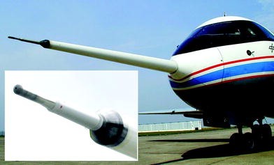
ATTAS upgrade—5-hole probe for air data
Fig. 9.49 
ATTAS upgrade—electronics box for 5-hole probe
-
(5)
New TCAS (Traffic Collision Avoidance System): The TCAS system was essential for the operation of ATTAS to meet the governmental regulations. When two aircraft come dangerously close to each other, the TCAS gives the pilots evasive instructions to avoid a collision.
-
(6)
VHF/COM, Mode S transponder, based on new operating regulations.
-
(7)
New visual system in ground-based simulator: In order to improve the test preparation and optimize the test sequence with the pilot in the control loop, a visual simulation (LCD projectors) with a view angle of 120° horizontally and 45° vertically was developed in the ground-based simulator.
-
(8)
New user interface with MATLAB/SIMULINK: Together with the new ExEC (Power PC), the interface to the user was improved considerably by the use of a model-based programming software MATLAB/SIMULINK for the modeling of technical systems due to its flexibility and simplicity [20]. SIMULINK enables the programming of dynamic processes by simple graphical linking of function blocks. For this purpose, a software was developed that allowed SIMULINK programs to run directly in the real-time application in the ATTAS experiment computer, see Fig. 9.50.
Fig. 9.50 
ATTAS flight control system design chain
-
(9)
New Boot/Recording Server (BRS) and Quicklook (see Figs. 9.51 and 9.52): On the one hand, the BRS served to provide the software for the various computers of the DV system (ROLM) and the ExEC, and on the other hand, to time stamp and record data streams from up to five different sources (DV system, measuring system, ExEC, twice video/audio) via the so-called ‘front end LAN’. The data was recorded on a removable hard disk, replacing the obsolete magnetic tape technology.
Fig. 9.51 
ATTAS upgrade—onboard data gathering and display
Fig. 9.52 
ATTAS upgrade—flight test engineer Michael Preß on FI cabinet with new operating console and display


These data were provided to arbitrary computers of the experimenter over the so-called ‘experiment LAN’ (see Fig. 9.53) and via the so-called ‘client LAN’ to several Quicklook PCs at the various operator stations. This gave the flight test engineer and the experimenters onboard a comfortable display of measurement and test data. With the BRS it was also possible to load the programs into the ROLM computers.

ATTAS upgrade—flight data display on all work stations
9.1.8 ATTAS Envelope Expansion
To take into account the possible failures of the technical equipment, the flight domain of ATTAS aircraft in the electrical mode of operation was limited to a minimum 500 ft above ground. As a result, flight test were not possible below 500 ft up to landing in FBW or SIM mode. This flight domain was particularly important, in particular, for the assessment of the handling qualities, as in this phase the pilot experiences the highest workload and control activity and the system characteristics play a dominant role.
Therefore it was planned to carry out the technical modifications on ATTAS in order to open up the flight domain to landing in the SIM-mode. For this purpose, it was necessary to supplement and modify the existing experimental system and to certify the same according to the federal regulations. In addition, it was necessary to ensure that the risk to the equipment and crew in the case of system faults remained below a residual probability.
This objective was achieved through precise definition or limitation of five measures: (1) possible applications of the test vehicle, (2) flight and operating procedures, (3) role of the safety pilot, (4) operating conditions and (5) system failure behavior.
The hitherto security concept up to 500 ft height corresponded to the originally formulated requirements and was certified for operation up to this height based on the hardware solution FBW-OFF button on the control column. However, it turned out that for an operation below 500 ft with the worst case of simultaneous control surface hardovers the aircraft reactions were so large that they could not be controlled by the safety pilot without the risk of undesired ground contact. The reason for this was that it took too long a time to switch off the experimental system via the FBW-OFF button. ATTAS had, therefore, two force sensors in all control axes, which allowed the safety pilot to separate the test system within a very short time by instinctive counter-reaction to its moving control devices.
In flight tests with control surface hardovers and for the determination of the shutdown times and fault transients, it was found that it was not possible to handle such faults without limiting the operating speeds of the control surfaces and an amplitude limitation in the aileron. For this reason, the rates of the actuation systems were adapted based on the flight test results by a switchable limitation in the software of the electrohydraulic control system from LAT. The already approved software was therefore to be re-certified. The work, funded by the German Federal Ministry of Education and Research (formerly BMFT), was carried out between 1995 and the end of 1996 and was shared by DLR, DASA Bremen (formerly VFW, MBB) and LAT as follows:
-
DLR:
(1) Overall responsibility, (2) proof of the ability to take over in the event of a hardover, (3) specification of actuator rate limits, (4) integration of components developed by DASA and LAT, (5) installation of the second lane of the duplex on-board computer system, including software, (6) Sensor technology, (7) system tests, and (8) certification by LBA and MPL of DLR.
-
DASA:
(1) Development and construction of a reliable switch box, (2) Error analysis, (3) Support for approval, and (4) Supervision of the modifications to the actuator electronics at LAT.
-
LAT:
(1) Modification of the actuator electronics, (2) Supplementing the limiter functions, and (3) Software qualification for certification.
The components developed and integrated into the overall ATTAS flight control system for the expansion of the flight domain are shown in Fig. 9.54. The new switch-box was activated by the flight engineer before crossing 500 ft altitude through a LIMITER ON switch. This enabled the operating rate limitation in the AEUs. The activation was displayed to both pilots in the cockpit (GO lamp). In the event of a fault, the NOGO lamp flashed.

ATTAS envelope expansion—flight control system modifications for safe landing in FBW-mode
The onboard computer system, which was designed from the outset as a duplex system, was supplemented with the second computer. By comparing the input and output signals, a passive system behavior was established in the event of a fault. All sensors, air data computer, inertial reference system and signal processing boxes were duplicated. The duplex onboard computer system was not subject to approval. The duplex solution was used to improve the operation, the acceptance by the safety pilots and the correct functioning of the test system before reaching the altitudes below 500 ft [21].
Figure 9.55 shows the limiting values as well as the risk areas in the roll axis for the individual actuation systems determined from flight tests with simultaneous hardovers in all axes and from the transients occurring during the takeover. Figure 9.56 shows time histories of the aircraft reaction to hardover in all actuation systems. The first fly-by-wire landing in the electrical mode of operation took place on April 30, 1999 at the Berlin-Schönefeld airport. Thus, ATTAS was available for applications with experiments in the FBW or SIM mode up to the touch-down (see Fig. 9.57). An example of the different control activities during a manual landing in FBW mode with sidestick (direct link), that is, without controller support, and with a control column is shown in Fig. 9.58. The high sidestick activities during the landing are clearly visible, which were caused by the much higher control sensitivity. The measures for the envelope expansion were funded by the BMBF.

ATTAS envelope expansion—risk areas and actuation system rate limits for the landing

ATTAS envelope expansion—transients in control surface hardovers during takeover by safety pilot

ATTAS after landing in FBW-mode on April 30, 1999

Comparison of control activities during landing task with control column and sidestick
9.2 VFW 614 ATTAS Applications and Results
Klaus-Uwe Hahn
With contributions from 12 coauthors
9.2.1 Overview
As already pointed out in Sect. 9.1.4, after the modifications and developments over a period of four years the VFW 614 G17 became available to DFVLR starting October 1985. Initially it was, however, required to establish certain working conditions for the experimenters that enabled universal utilization of FBW/L control in the experimental mode up to in-flight simulation. Accordingly, the first intensive utilization over first few years focused on the comprehensive proof of reliable functioning of the FBW system, installation and certification of the nose boom with a high-precision flow sensor, and accompanying flight tests for system identification.
By means of system identification methodologies, a highly accurate flight-validated mathematical model of the ATTAS aerodynamics was determined, which forms the basis for the in-flight simulation (see Chap. 3). In 1989, the first tests were carried out for in-flight simulation. After its last flight as a part of an experiment on November 11, 2011, ATTAS had completed 2912.06 flight hours for research purposes with 3328 take-offs and landings over a period of 27 years. Subsequently, it was flown on December 7, 2012 to the German Museum in Oberschleißheim. The most important utilization programs which were carried out from 1985 to 2011 are chronologically summarized in Table 9.2. A few selected projects are briefly elaborated hereafter to illustrate the spectrum of ATTAS capabilities and utilization.
9.2.2 Hermes Spaceplane
Dietrich Hanke
Hermes was a spaceplane designed by the Centre Nationale d’Etudes Spatiales (CNES), the French Space Agency. It was to be launched into the orbit from the Ariane 5 launcher of the European Space Agency (ESA). The Hermes Spaceplane was to be used as a recovery transport system with a crew of three, similar to the Space Shuttle of the USA. In 1987, the Institute of Flight Mechanics of DFVLR was commissioned by the CNES to develop a concept and specification for an in-flight simulator for the Hermes Spaceplane. The in-flight simulator was to be used as a training device for the astronauts, particularly for familiarization during the difficult phases of manual approach and landing [22,23,24]. The in-flight simulator, called Hermes Training Aircraft (HTA), was to simulate the glide path from 37,000 ft altitude until touch down (see Fig. 9.59). A new technique based on target lighting array system called GRATE was to be used for flying qualities assessment and pilot training (see Sect. 12.3.2).

Hermes precision approach and landing trajectory
To arrive at a suitable host aircraft configuration for the planned HTA simulator aircraft, three candidates were investigated: (1) three engine business jet Dassault Falcon 50, (2) two engine business jet Bombardier Challenger and (3) two engine business jet Grumman Gulfstream IV. Two variations for the position of the evaluation cockpit were proposed (see Fig. 9.60): (1) one training and one safety pilot located in the basic aircraft cockpit and (2) an additional cockpit identical to the Hermes cockpit layout on top of the fuselage for a complete Hermes crew with the safety pilots in the basic aircraft cockpit. The performance calculation showed that the landing trajectory of the Hermes Spaceplane was only possible by using full in-flight thrust reversal, deployed air-brakes and extended landing gear of the host aircraft. Figure 9.61 shows the different host aircraft in the position to adapt the eye height of Hermes at touchdown.

HTA with added cockpit for crew training

Landing situation for the different host aircraft with respect to identical eye height of Hermes
Anticipating that DFVLR would develop a model following control for HTA, it was designed based on the Hermes design data and implemented in the ATTAS in-flight simulator. The objective was to evaluate the flying qualities of Hermes in level flight and to demonstrate the required in-flight simulation quality. The flight test measured data showed an excellent model following quality as shown in Figs. 9.62 and 9.63, where the time responses in pitch and roll axes of the Hermes model and ATTAS are compared respectively. Both flight measured and the in-flight simulated responses are nearly identical.

Comparison of Hermes and ATTAS in-flight time histories

Hermes in-flight simulation (comparison of time responses in the roll axis)
Eventually, the Hermes project was cancelled because the weight of Hermes was not within the Ariane 5 rocket lift capabilities. Furthermore, the financial and political scenarios had changed in Europe (see also Sect. 11.5).
9.2.3 Fairchild-Dornier 728 Jet
Klaus-Uwe Hahn
During 2001 and 2002 ATTAS was deployed for a particularly interesting application, utilizing its capability of in-flight simulation to support the preparation of the first flight of the Fairchild-Dornier 728 Jet (Do 728 Jet) and its certification process. The 728 Jet (see Fig. 9.64) was conceptualized as a twin-jet passenger transport aircraft. In its basic version, it was designed to carry 75 passengers and to have a glass cockpit from Honeywell (EPIC System). It had a span of 27.12 m and a length of 27.04 m, and was developed almost to prototype maturity, despite recurring financial difficulties. Based on the anticipated excellent flight performance the German Lufthansa had secured in advance several procurement options. However, the development of the 728 Jet was discontinued just before its maiden flight in 2004 due to bankruptcy of the company. The fuselage of the first prototype was later employed for research on cabin air ventilation at DLR in Göttingen.

Fairchild-Dornier prototype Do 728 Jet TAC 01
In 2001, the Institute of Flight Systems of DLR was contracted by Fairchild-Dornier to analyze the flying qualities of the 728 Jet and evaluate the flight control system concept. These included analytical studies applying flying-qualities and PIO criteria, using linear and nonlinear aircraft mathematical models [25]. In addition to these analytical studies, investigations were also carried out in a ground-based simulator and by executing numerous in-flight simulations with ATTAS. To perform the flight tests safely, accurate design and operation of flight-control laws of the 728 Jet was verified in advance including risks analysis of uncertainties in the aerodynamic parameters [26, 27]. To reproduce the control behavior accurately, the control column of ATTAS was modified to match that of 728 Jet. The control forces acting on the to-be-simulated aircraft were artificially emulated [28].
By simulating the 728 Jet flight characteristics applying explicit model-following control (see Chap. 3), the flying qualities were investigated by test pilots under real flight conditions [29]. The in-flight simulation of Hermes Training Aircraft described in the forgoing section was based on the completely linear model of the to-be-simulated vehicle as well as linear model-following control. Thus the excursions about the chosen reference flight condition were limited. In contrast, during flight experiments with 728 Jet a totally nonlinear in-flight simulation was implemented for the first time worldwide. For this purpose, the models of the to-be-simulated aircraft (the 728 Jet) and the model-following control were completely nonlinear. For example, the aerodynamics data tables from wind tunnel measurements were incorporated including all existing nonlinearities. The restrictions encountered in the linear simulation, namely small excursions around the reference condition, could thus be eliminated. Only through this innovative approach it was possible to meet the accuracy requirements.
A total of eight flights were carried out with a flight time of more than 17 h, in which 23 predefined initial flight conditions with different configurations, masses and centers of gravity were simulated. Thereby 25 switchable malfunctions were investigated and evaluated, including degraded flight control modes and mode transitions of the 728 Jet. Typical errors were for example: (1) engine failure, (2) flight controller in direct link mode (Direct Law, fly with “electrical control rod”), (3) yaw and pitch damper failure, (4) oscillating elevator, aileron and rudder, and (5) hydraulic failure.
When the flight controller is operated in the direct link mode (Direct Law), it implies the complete failure of the electronic flight control laws. In such a case the aircraft flies without any computer-aid, that is, with a direct proportional transmission of the pilot inputs to the control surfaces (flying with “electric rod”). The in-flight simulation quality with ATTAS had Level D/E quality, meeting the highest quality requirements for certification of today’s training simulators [30]. As a typical example, Fig. 9.65 shows the time histories during lateral Dutch roll responses. The longitudinal motion variables are plotted on the left (from top to bottom: pitch command, thrust command, pitch acceleration, pitch attitude change, and airspeed variation), and the lateral-directional motion variables are shown on the right (from top to bottom: roll command, yaw command, roll acceleration, change of bank angle, and change of angle of sideslip). The resulting very high model-following quality is discernible from the figure. The same quality was also achieved for other types of maneuvers not shown here. This was the case for both the normal flight conditions as well as for the investigated system failures. This high simulation quality was the prerequisite for the utilization of the ATTAS 728 Jet in-flight simulation for the training of the test pilots prior to performing the planned first flight [31].

ATTAS In-flight simulation of Do 728 Jet Dutch roll dynamics
9.2.4 Flying Wing NACRE
Jana Schwithal
The usual analytical methods and classical criteria for the flight mechanical assessment are often validated only for conventional aircraft configurations, consisting of fuselage, wings, and horizontal and vertical tail planes behind the main wing [32]. Their validity for different configurations is uncertain. Therefore, validity of analyses pertaining to flying qualities and safety, carried out during aircraft development phases, need to be verified in flight. Particularly in the case of unusual configurations, such as flying wings, flight test is an essential part of the development. However, without in-flight simulation (see Chap. 3) the flight tests would be feasible only after the construction of a prototype. But such a prototype is available at a very late stage in the development process. In addition, it must also be ascertained prior to the first fight that the aircraft dynamics does not exhibit a safety critical behavior. With the in-flight simulator ATTAS unconventional configurations can, however, be efficiently tested under real flight conditions to detect and rectify possible deficiencies during a very early stage of their development. The innovative approach of nonlinear in-flight simulation described in the foregoing section guarantees highest possible accuracy of the experimental evaluation. Accordingly, it was applied to the flying wing configuration that was developed within the EU-project NACRE (New Aircraft Concepts Research), (see Fig. 9.66) [33].

European flying wing project NACRE
Such a flying wing aircraft, often called BWB (Blended Wing Body), is characterized by the lack of the conventional tubular fuselage. The passengers are accommodated in a specially designed center segment of the wing. In contrast to the conventional fuselage, this central part of the blended wing-body generates primarily the required lift. Contrary to a conventional vertical tail, this configuration had two relatively small vertical fins at the end of the middle wing segment. It did not have an elevator. The trailing edge flaps on the middle wing were used for longitudinal control. The flying wing configuration was designed as a large long-range aircraft with a maximum take-off weight of approximately 700 tons and a seating capacity of 750 passengers.
The handling qualities of flying wing configurations are often critically affected by the absence of the stabilizing tail and due to short lever arms of the control surfaces. On the other hand, an aircraft can be successfully introduced in the regular service, only when it is easily and safely controllable. For this reason, the elaborate evaluation of the flying qualities was carried out of the NACRE flying wing configuration. In addition to theoretical analyses with the help of flying qualities criteria, an in-flight simulation with ATTAS was utilized to ascertain through pilot evaluations the critical aspects pertaining to applicability of such criteria to unconventional configuration.
A total of three flight tests were carried out, in which the flight dynamics of the flying wing configuration was simulated with ATTAS and evaluated by two pilots. The first flight served the purpose of familiarization with flying the unusual configuration and with its dynamic behavior. For this purpose, the pilots carried out simple maneuvers and excited the aircraft’s eigenmotion through control inputs. Hereby, the capability of ATTAS to replicate a significantly different configuration was continuously examined. As shown in Fig. 9.67, ATTAS and the flying wing configuration being investigated have a completely different geometry and differ significantly in size.

Scale comparison between ATTAS and flying wing NACRE
The flight experiments showed, however, that despite these differences the motion of the ATTAS host aircraft and that of the to-be-simulated aircraft model matched fairly well for all important parameters. With the exception of airspeed errors, resulting from the low ATTAS engine dynamics which was not directly sensed by the pilot, the in-flight simulation achieved the so-called Level-D quality, see Fig. 9.68. It was clearly demonstrated that such unconventional aircraft configurations could be realistically investigated with ATTAS.

Time history comparison of lateral dynamics between ATTAS and simulated NACRE model (with tolerance bands for acceptable Level-D simulator quality)
In the two subsequent flight tests, the test pilots evaluated the flying qualities of the flying wing configuration during different maneuvers using the Cooper-Harper rating scale [34]. The flight tasks comprised of different turning flights and ILS approaches. The turning maneuvers were used to analyze the lateral dynamics, which were identified as critical in the preliminary analytical investigations. The ILS approaches served to evaluate the performance during precise flight path control. All maneuvers were carried out with the basic configuration of the flying wing.
Subsequently, the same flight maneuvers were repeated with a control-augmented variant of the flying wing. For this purpose, the aircraft model was equipped with a flight controller in order to support the pilots to control the vehicle and improve the flight characteristics. The pilot evaluation indicated that the unaugmented flying wing configuration was not controllable, resulting in strong deviations from the desired flight condition. For example, an undesired buildup of angle of sideslip was observed during curved flights. For the control augmented configuration both pilots noticed significantly improved flying qualities with reduced workload.
The improvements in the flying qualities were limited by inadequate yaw control due to the relatively small vertical tail and short lever arms, and due to the sluggish behavior of the aircraft about the longitudinal axis resulting from the large roll inertia due to the extreme wingspan. Satisfactory flying qualities were not achieved in all the cases [35]. The in-flight simulations with ATTAS demonstrated that further development work is necessary before the investigated flying wing configuration could be implemented into a real aircraft.
9.2.5 Gust Load Alleviation (1990–2011)
Klaus Uwe Hahn
LARS (Load Alleviation and Ride Smoothing System) was one of the first investigations that were carried out with the ATTAS at the beginning of nineteen-nineties. The objective hereby was to actively reduce the effects of vertical gust (vertical movements of air mass) on the aircraft motion; in other words, on the accelerations at the center of gravity, with the primary aim of improving passenger comfort. On encountering vertical updraft gusts the aircraft angle of attack increases and thereby the lift. This increased lift force leads to an additional load on the aircraft structure and to an upward acceleration of the aircraft and passengers. These effects reverse on encountering a downwind, resulting in downward acceleration, which is perceived by the passengers as unpleasant. It is similar to a fast downhill ride in a roller coaster. However, if the lift could be maintained constant in the presence of gust, the additional accelerations would disappear and thereby the unwanted aircraft reaction, too (see also Sect. 6.3.3). This can be accomplished by the use of special, fast responding trailing edge flaps on the wings, such as those that are available on the ATTAS, called the DLC (Direct Lift Control) flaps. The deflections of these DLC flaps change the wing profile and thus the lift.
The LARS concept is based on the principle of disturbance compensation. Figure 9.69 shows the computation of DLC flap deflection δ and elevator command η from the gust induced additional angle of attack αW [36]. Thereby, the disturbance flow ahead of the aircraft is determined at first. In the case of ATTAS, the flow sensor on a noseboom provided this information. Assuming that the aircraft aerodynamics is known, and therewith the effect of the disturbance, the deflection of the trailing edge flaps can be computed that is necessary to compensate the disturbance. The deflection of wing flaps leads to changes in the pitching moment as well as in the downwash behind the wings, and thereby the flow angle of attack at the horizontal tail. In a similar way the flow due to gust disturbances and its aerodynamic effects change, when they reach the horizontal tail. If the pitching moment balance of the aircraft is to be maintained in the presence of gusts, corresponding deflections of the elevator are necessary to compensate the additional pitching due to gust disturbances. The advantage of the gust disturbance suppression concept is that control interventions are necessary only when flow disturbances are measured. This so-called open-loop control system does not affect the aircraft flying qualities in case of a pilot intervention.

LARS principle
During 1990–1993, a large number of flight test were performed with ATTAS to successfully demonstrate the operational principle of LARS [37]. The vertical accelerations due to gusts could be reduced by 12 dB (that is, about 70%) in a frequency range of 0.2–2 Hz, that is particularly sensitive to passenger comfort (see Fig. 9.70). This highly promising result pertaining to vertical accelerations was, however, at the cost of more noticeable horizontal accelerations. This fact could also be verified in the simulations (see Fig. 9.71) [38]. The use of the thrust force to compensate for this side effect in the longitudinal axis was ruled out, because the thrust modulation was much too sluggish for these relatively high-frequency processes. However, even in this case ATTAS provided an alternative. The two outermost DLC flap pairs 1/2 and 5/6 on each wing were deflected oppositely as split flaps for drag control. Rapid longitudinal force changes could be achieved by activating these fast responding flaps. The inner flap pair (flap 3 and 4) was, as before, available for the generation of vertical forces. With this concept of a Gust Management Systems (GMS), the vertical and horizontal accelerations due to gust disturbances could be successfully reduced [39, 40], (see also Sect. 6.3.3.3).

Power spectral density of vertical accelerations

Increase in the horizontal acceleration due to reduction of vertical acceleration by DLC flaps
Yet another application of ATTAS during 2008 and 2009 was the feasibility study of structural vibration damping with the aid of adaptive control in the EU project ACFA 2020 (Active Control of Flexible 2020 Aircraft) [41]. Thereby, using the flow sensor signal at the nose boom the first bending mode of engine nacelles at 3.5 Hz could be successfully damped.
Furthermore, in addition to the reduction of accelerations at the center of gravity based on the LARS approach, the possibility of damping the symmetrical wing bending was investigated within the EU project AWIATOR (Aircraft Wing with Advanced Technology OpeRation). This refinement of LARS to the GLAS concept (Gust Load Alleviation System) was carried out for a large flexible aircraft, whereby not only the passenger comfort could be improved but also the damping of the wing bending mode resulting in the reduction of the wing root bending moment [42]. The operation of the GLAS concept could be successfully demonstrated in computer simulations. Figure 9.72 shows the time histories of a vertical wind disturbance (on the left) and the resulting wing root bending moment (on the right). The red curve illustrates without gust load reduction system, the green curve with the original (static) LARS concept, and the blue curve with the GLAS concept. The reduction of the wing root bending moment is clearly discernible.

Simulation results with GLAS (gust load alleviation system)
The flight demonstration of the GLAS concept was, however, not completed within the AWIATOR project. It was pursued in the succeeding project FTEG-InnoLA (Flight Physics Technologies for Green Aircraft—Innovations for the efficient simulation and testing process chain for loads and aeroelastics) as part of the 4th National German Aviation Research Program. Having adapted the GLAS design for an ATTAS in-flight demonstration, initial functional tests were performed in flight, followed by further flight tests to evaluate the system. The intended improvements could initially be achieved only in a very narrow frequency range. As such the control system had to be redesigned [43]. During the flight test on November 11, 2011, with an improved control system the atmospheric conditions were very stable and as such the system performance could not be evaluated satisfactorily. Another flight test with the GLAS concept was planned for the beginning of 2012. However, during the yearly inspection the ATTAS was grounded due to intolerable and irreparable engine defects. Thus, the flight on November 11, 2011 was the last mission of the VFW 614 ATTAS. Although ATTAS served as an experimental platform for numerous scientific applications, coincidently, the first and the last research mission of this extraordinary technology demonstrator aircraft were dedicated to gust load alleviation research.
9.2.6 Flight Control Algorithms for a Small Transport Aircraft (1993–1996)
Klaus - Uwe Hahn
An electronic flight control system was developed for a small 100-seater passenger transport aircraft within the technology program of the DASA (Daimler-Benz Aerospace Airbus). It was finally implemented on the VFW 614 ATD (Advanced Technology Demonstrator, see Sect. 6.3.7). For this purpose the flight control laws (FCL) were developed and flight tested on the VFW 614 ATTAS, jointly by DASA and DLR. The project dubbed SAFIR (Small Airliner Flight Control Laws Investigation and Refinement) was launched in April 1993 to address this task, with the objective of optimizing, validating, demonstrating, and evaluating the control laws in flight. Just six months later the first flight tests were carried out [44, 45]. The to-be-examined control algorithms were developed by DASA (Robert Luckner) using the development tool HOSTESS (High Order Structuring Tool for Embedded System Software) with automatic code generation [46].
In the first phase of the project, the standard flight control laws in the so-called Normal Laws mode were investigated, including automatic Envelope Protections (see Fig. 9.73). The FCLs were optimized iteratively as shown in Fig. 9.74. They were checked in the ATTAS ground-based system simulator prior to the flight trials. If necessary the adaptation could be carried out with HOTESS. Subsequently, after comprehensive ground testing the experimental software was approved for flight operations. This experimental software was ported as an independent program package into the ATTAS experimental and control computer (ERR) and thus integrated into the ATTAS-DV data processing system (see Fig. 9.75). An experiment-specific interface supplied all the necessary information, coming from different sources including artificially generated sensor signals, required by the flight control law algorithms. The control commands calculated by the flight control algorithms were then returned to the ATTAS-DV system and converted into control surface deflections by the fly-by-wire system. During the first project phase, the focus was on the evaluation of the functionalities and assessment of the flying qualities in the normal laws mode [44]. Furthermore, the flight envelope protections were verified to avoid critical flight conditions for the maximum airspeed and the maximum permissible angle of attack.

Different envelope protection modes within the normal laws mode

Iterative optimization of flight control laws

Experiment configuration of SAFIR project (first phase)
In the second project phase, system-specific characteristics of the flight control system were tested and demonstrated [45]. For this purpose, the FCLs were programmed and implemented on the Flight Control Law Computer (FCLC) in two different programming languages (dissimilar software in ADA and FORTRAN) to generate control commands and reference signals for monitoring. The FCLC had to be certified for onboard operation and could be connected to the central communication computer (ZKR) of the ATTAS data processing system via six ARINC 429 channels. Three ARINC channels supplied the FCLC with the necessary measured signals, and other 3 ARINC channels fed the calculated control and display commands back into the ATTAS system (see Fig. 9.76). To enable testing of flight envelope protection functions for the bank angle, the ATTAS FBW flight envelope had to be extended to 45° of bank angle. installation of additional displays for angles of attack and sideslip to the pilots was mandatory to test the automatic angle of attack protection, which was close to the ATTAS stall-boundary.

Experiment configuration of SAFIR project (second phase)
To verify the control laws functional efficiency in the entire flight envelope, computer-generated synthetic signals as well as manual control inputs by the pilot were used. For the flying qualities assessment, the evaluation pilot had to fly a sequence of predefined flight maneuvers with course and altitude changes. The assessment of handling qualities of the control-augmented aircraft was carried out by the pilots using Cooper-Harper Ratings (see Fig. 2.6) [34]. During the period from 1993 to 1996, more than 300 test sequences were successfully tested in 12 test flights with a total flight time of 32 h. A total of nine different software configurations with 110 modifications were evaluated. The flight control laws investigated in the SAFIR project were later implemented in the industrial VFW 614 ATD project (see Sect. 6.3.7).
9.2.7 High-Performance Synthetic Vision System (1995–1997)
Dietrich Hanke
A Synthetic Vision System (SVS) with synthetic outside view was developed jointly by the Technical University of Darmstadt and VDO-Luftfahrtgeräte (VDO-L). This development was supported by the BMFT. The basic concept of the new vision system consisted of a 3D representation of the flight path and that of the surrounding terrain. Both of these were shown on the Primary Flight Display (PFD) as well as on the Navigation Display (ND), together with 3D representation of the terrain and the position in bird’s eye view. In August 1997 this system was implemented and tested on the ATTAS [47].
The motivation for the development of SVS was the fact that there were various accidents in poor weather conditions, where the airplanes were flown directly into the mountains (Controlled Flight Into Terrain—CFIT), even when it was guided by air traffic control. The above approach was aimed at improving the situational awareness of the pilot and the flight safety during the entire Gate-to-Gate operation by combining the flight information with the synthetic terrain vision.
Depending upon the flight phase from taxiing, takeoff, cruise, landing, and docking at the gate, all necessary information was displayed by the SVS throughout the entire flight. Thus, suitable synthetic vision of the outside view was available to the pilot at any time. Furthermore, a predictor display, indicating the flight path eight seconds in advance, was provided in the PFD to assist the pilot. Color changes in the predictor were used to indicate flight operational limits. During the landing the flight path (ILS) was represented by a rectangle corridor (Channel Display), which the pilot had to follow until touchdown. Figures 9.77, 9.78 and 9.79 show the display formats for different flight phases as an example.

Display in PFD: during taxiing

Display in PFD: during landing approach with indicated approach corridor

Display in PFD: during final landing
Experimental System
The main components of the experimental systems were: (1) Primary Flight Display (PFD), (2) Navigation Display (ND), (3) Inertial reference system Honeywell H 746, (4) Navigation computer, (5) Data base computer Harris Nighthawk, and (6) High-performance graphic computer, Silicon Graphics ONYX.
A large commercial liquid crystal display (LCD) was mounted in front of the basic instruments as a cockpit display (see Fig. 9.80). The display could be folded down in order to provide the basic ATTAS instruments for take-off and landing. All experimental components were installed in two closed cabinets in the cabin near the loading door. The computer cabinet is illustrated in Fig. 9.81. Several interfaces provided the connection to the electrical power system and the communication with the on-board measuring system.

LCD display in ATTAS cockpit for synthetic vision

Computer cabinet from external user in ATTAS
The experimental system was based on three advanced technologies: (1) Precision navigation with differential GPS, (2) World-wide 3D Geo data base, and (3) Commercial high-performance graphic workstation with 4D display software functions.
The aircraft position, airspeed, accelerations, and attitudes were calculated by the precision navigation system. The data from different sensors were compared and checked for plausibility. A filtering algorithm was developed to compute the precise aircraft position with an accuracy of less than a meter. Based on the precise position, appropriate datasets were selected for the terrain information from the Geo Database and transferred to the display computer.
In addition, the eyepoint of the pilot was calculated, which is needed for the exact synthetic 3D vision to be presented to the pilot. All vision data processed in the high-performance graphic workstation were displayed in real time to the evaluation pilot and the system operator in the cabin. The PFD and ND information were displayed on the large screen in the cockpit.
Flight Tests
The flight test campaign with 22 flights and 35 pilots was carried out at the international airport in Frankfurt in August 1997. The flight tasks comprised of the approach of beacons, virtual fixes, terrain collision situations, straight and curved landing approaches, and taxiing on the ground. All participating pilots were experienced active airline pilots. They were made familiar with the ATTAS aircraft, the flight test equipment, the 4D navigation guidance functions, the display symbology, and the flying tasks before the flight test campaign.
To briefly summarize the evaluation, the basic concept of the synthetic vision was well accepted by the pilots and it provided a significant improvement in the situational awareness compared to conventional display systems. The concept allowed manual or automatic landing approaches with high precision and surveillance. Furthermore, the synthetic vision turned out to be quite important for efficient taxi guidance to enhance the airport capacity also in a case of bad weather conditions.
Low-Level Flight Guidance
In yet another project, with the participation of Daimler-Benz Aerospace AG, Honeywell Control Systems and the Lufttransportgeschwader (LTG 61—Air Transport Wing of the German Air Force), the synthetic vision system was employed for flight testing of an autonomous manual low-level flight guidance system in 1996 [48]. The Harz mountain terrain in the northern part of Germany was digitized for an area of 217 × 68 miles and the data stored in the mission database onboard the ATTAS. The resolution of the terrain data was 1212 × 1181 ft with a sight cone of 60°. Taking into account the ATTAS performance data, 3D low-level missions at 150 ft above the ground were planned through the Harz Mountains. Although the actual test flights were carried out in flight altitudes of 10,000 ft, all information were displayed to the pilot as if he would be virtually flying at a height of 150 ft above the ground. The outside view from the cockpit was completely curtained-off. The synthetic vision provided to the pilot included the terrain topography, such as roads, lakes, cities and railroads. In a case of a risk of collision with the terrain the terrain color was changed to red.
The main guidance assistance was provided by the channel display for the flight path and the predictor. Without these functions, a manual low-level flight would not have been possible. Figures 9.82, 9.83, and 9.84 depict typical low-level flight situations on the PFD and ND. Figure 9.85 shows a comparison of the commanded and actual flight path for the entire low-level flight route. It is apparent that the pilot flew the nominal flight path quite accurately.

Low-level flight information in PFD

Low-level flight information in ND

Low-level flight with mountain obstacle in ND

Low-level nominal and actual flight path over the Harz Mountains
9.2.8 Enhanced Vision for All-Weather Flight Operation (1999)
Klaus - Uwe Hahn
As a part of the EU project AWARD (All Weather ARrival and Departure), pilot assistance systems were tested, which would allow a pilot to operate aircraft safely in the absence of the exterior view, regardless of the quality and precision of the flight guidance installations at the airport [49]. The objective was to carry out the flight operation with the equipment available onboard according to the “category” CAT III criteria, with a decision height (DH) of less than 50 ft and a visibility (RVR, Runway Visual Range) of 75 m only. For this purpose, two different concepts of pilot-assistance were pursued and evaluated, both based on the use of a differential GPS (DGPS), which is cost-effective compared to the conventional ILS (Instrument Landing System) or MLS (Microwave Landing System). One of these two concepts was a so-called SVS (Synthetic Vision System), which provides the pilot with an artificial synthetic exterior view (see Sect. 9.2.7). This system was tested in a ground-based motion simulator [50].
For the second pilot-assistance concept, a sensor-based artificial outer visibility was provided so that flight under quasi-visual conditions was possible. This system called EVS (Enhanced Vision System) was tested in flight using ATTAS. The basis for EVS was the availability of suitable sensors, which operate in a frequency range that expands the field visibility of the human eye so as to use additional, quasi-optical information. For this purpose, a millimeter wave radar (MMWR) and a forward-looking infrared (FLIR) camera were used, with which the necessary additional visual information was gathered [51]. The external view generated thereby was displayed on a HUD (Head-Up Display). Particularly, on a special transparent disk (Combiner Unit—COU) in front of the pilot’s eye, on which also other useful information were provided. The projection on the transparent disk is such that a sharp image is formed when eyes focus far ahead of the aircraft. In this way, without having to focus differently, the pilot captures all the information, including sensor visual information, necessary for guiding the aircraft.
The overall EVS system included a large number of components, all of which were integrated at suitable places in the aircraft. They all had to be certified for flight operation. Figure 9.86 shows these components and their location of installation in ATTAS, where COU denotes the combiner unit, FLIR the forward looking infrared, MMWR the millimeter wave radar, HCP the head-up display control panel, HFDC the head-up display computer, MTR the mounting tray, OPU the optical projection unit, PU the processing unit, RCU the radar control unit, RPU the radar processing unit, RRCU the radar recorder control unit, and SMU the servo-mechanism unit. Figure 9.87 shows the two sensors mounted on the front bulkhead. The infrared camera (the small black cylindrical disk) on the top and the millimeter wave radar (large ocher-colored cylinder) can be seen in the figure. The square-sized pressure-tight plug plate, clearly visible in the figure, covered the hole cut in the bulkhead. It enabled the electrical connections between the sensors and the devices housed in the fuselage. To maintain the aircraft center of gravity within the permissible limits, the heavy special recorder for recording MMWR data had to be mounted far behind in the tail. The so-called EVS container was installed in the passenger cabin. Many smaller devices and system components were accommodated in this central part of the overall system, including the central processing unit (PU).

EVS components and their installation in ATTAS

Millimeter wave radar and infrared sensor on ATTAS
The sensor signals for the raster display on the HUD were processed in the PU. In this display, the information, which is usually presented in the primary flight display (PFD), was superimposed (in the Stroke Mode). Thereby, the pilot receives all the important information with a single glance forward in the direction of the flight, looking simultaneously through the transparent pane (Combiner Unit) of the HUD and through the cockpit window. This data fusion is shown in Fig. 9.88.

Sensor-view information and flight guidance display in the HUD
The efficacy of an EVS is demonstrated in Fig. 9.89. Exemplary is the approach under poor visibility conditions to an airport, which is equipped only with an ILS of CAT I quality. According to CAT I conditions, this implies that when the pilot reaches the decision height (DH) of 200 ft above the runway, he must initiate the go-around if he cannot recognize the runway. On the other hand, with EVS, it is possible to provide the pilot with a supplemental vision of the outside, which is beyond the visual frequency range of human eye, prior to reaching the decision height. With this artificial visual information, the pilot could continue the approach to a height of 50 ft above the runway, even without a real outside view. This corresponds to a decision height according to the more precise CAT III requirements. Only at this new EVS decision height, the pilot should be able to recognize the runway in order to continue the approach. If the runway is not recognizable at this altitude, a go-around would have to be initiated despite EVS. Nevertheless, it is worth to note that high-quality CAT III approaches and landings are possible with EVS under considerably poorer visibility conditions, even at an airport that is equipped with just CAT I flight guidance aids.

Approach procedure with EVS meeting CAT III requirements using CAT I landing system
Figure 9.90 shows the picture captured by a Handycam taken from the perspective of the pilot through the HUD. The information which is usually displayed in a PFD can be easily traced. The dashed-dotted blue line marks the contours of the instrument panel. Below this line, normally, the pilot would not have a view of the runway in front of him. However, since the EVS sensors are installed in the aircraft nose in front of the instrument panel, the view of the runway is not obscured. This information is presented to the pilot on the HUD, so that he can even virtually view through the instrument panel.

View through the HUD
9.2.9 Fast and Robust Design of Autopilot Control Laws for Automatic Landing
Gertjan Looye
As a part of the European project REAL (Robust and Efficient Autopilot control Laws design, EU-FP5), an efficient design process for robust flight control laws was developed and applied to CAT-IIIb-capable automatic landing systems. The REAL project consortium consisted of Airbus, NLR, TU-Delft, and the DLR institutes of Flight Systems and Robotics and Mechatronics (now: System Dynamics and Control) [52, 53].
During the first phase of the project, a process based on NDI (Nonlinear Dynamic Inversion) was developed for controlling the aircraft attitude and TECS (Total Energy Control System) for decoupled tracking of flight path and airspeed references. Attitude control laws usually need to be individually tuned for each type of aircraft. NDI uses inverted model equations to adapt to the individual aircraft type, allowing for easy automation of the design when a sufficiently good model is available.
The software tool MOPS (Multi Objective Parameter Synthesis) was then used to automate the tuning of the control law parameters to meet the performance and robustness requirements. As part of the CAT-IIIb certification process, extensive Monte-Carlo analyses were performed. These results were directly incorporated in the parameter optimization. To demonstrate robustness, the developed process was first applied to the RealCAM (REAL Civil Aircraft Model), a simplified Airbus model, and then extensively evaluated in a qualified Airbus simulation tool (see Fig. 9.91, upper part).

Structure of the REAL project in sequential order
The efficacy of the process was then successfully demonstrated by a re-design for ATTAS within a short time frame (see Fig. 9.91, lower part). The developed design process was adequately tested, as ATTAS has quite different flight characteristics and the resulting control laws had to be flight ready.
To minimize risks of flight testing newly developed flight control laws all the way to landing touch down, dedicated flight test procedures were developed. After successful landing tests on virtual elevated runways (starting at 500 ft, then stepwise reduced to 100 ft) at Hanover airport, six actual fully automatic landings were performed at Magdeburg-Cochstedt.
9.2.10 Reduced Gravity Experiments (2008)
Dirk Leißling
Investigations under reduced or zero gravity are important not only for space missions but also in other fields of natural sciences. A special flight test technique is needed in which the aircraft’s acceleration cancels the earth’s gravitational force. Such a condition can be created over a limited period of time in an aircraft through a parabolic flight path relative to the center of the Earth (see Fig. 9.92). With a less curved flight path, the relative gravitational force is not eliminated completely, but only reduced by a certain amount. Thus, through this special flight technique, the gravitational influence of heavenly bodies of lower mass, for example, the moon or the planet Mars, can be simulated. However, to maintain this flight condition over a period of time using only manual flight control is a difficult task. Furthermore, the unavoidable atmospheric turbulences affect the precision of maintaining a target load factor. Automatic control augmentation alleviates this problem significantly.

Principle of parabolic flight
The beginnings of parabolic flights can be traced to the nineteen-fifties, when the effects of zero-gravity on human organism were investigated on future astronauts and cosmonauts. Also, technical devices and systems could be tested for their operational capability in Space. After the nineteen-eighties, the scope of application was expanded to fields other than astronautics. Special aircraft used for parabolic flights were, for example, the Ilyushin 76 MDK in Russia or the Boeing KC-135A (1995–2004), McDonnell Douglas DC-9-C9B and Boeing 727 operated by NASA. In Europe, parabolic flights were performed from 1988 to 1995 with a Sud-Aviation SE 210 Caravelle. Since 1997, their role was taken over by the Airbus A300 ZERO-G of the company Novespace, which is operated—like its predecessors—with direct participation of the French space agency CNES (Centre National d’Études Spatiales) on behalf of the European Space Agency (ESA). With this aircraft, simulated zero gravity phase is maintained for approximately 20–25 sec [54,55,56].
Motivation for Parabolic Flights with ATTAS
Since 1999 DLR was one of the A300 ZERO-G users, with one or two campaigns every year. In May 2008, the project manager and program leader of DLR parabolic flights, U. Friedrichs, became aware of the alternative offered by the ATTAS, particularly of the technical capabilities based on the freely programmable flight control system. The short-term availability of this aircraft seemed to be more interesting than the commercially marketed A300 ZERO-G of Novespace. There was also a tangible interest in the utilization of ATTAS by the Institute for Geophysics and Extra-Terrestrial Physics of the TU-BS as well as by the DLR Institute of Space Systems in Bremen. For their experiments, a simulation of the gravitational acceleration on Mars planet was needed, which is 3.71 m/sec2 (0.378 g), about one-third of the earth’s gravity of 1 g.
The programmable flight control system provided by ATTAS was advantageous for “Martian parabolic flights” in terms of meeting the defined tolerances through better reproducibility compared to the manual control of other aircraft for such experiments. Furthermore, atmospheric disturbances could be compensated much faster and more exactly by an automatic controller. The experiments pertained to the greenhouse effect caused by the emission of dust particles (solid-state greenhouse effect) and the investigation of ground distortion properties under Martian conditions [57]. Having verified the technical feasibility based on geometry, mass, and electric power consumption, the first campaign was planned, comprising of 90 parabolic maneuvers in six flights with ATTAS [58].
Development of Control System
Initially, it was proposed to use an automatic control system only for the parabolic arc of the flight path, with manual initiation and termination. However, due to complexity, better reproducibility was possible only through automation of the complete maneuver. Accordingly, an automatic controller for the entire flight path was designed and parameterized based on the non-linear flight-mechanical model of the ATTAS. It was tested and evaluated under real-time conditions on the ground-based system simulator. A simple system was developed for lateral attitude control which adjusts the bank angle to zero degrees at the beginning of each maneuver and maintains it thereafter. The longitudinal controller was more complex and consisted of five different modules for the five main segments of the maneuver (see Fig. 9.93).

Entire profile of Mars parabolic maneuver with controller for five segments
-
Phase 1: After manual activation of the SIM mode by the experimental pilot, the engine exhaust gas temperature (EGT) is checked. It is a measure of the available thrust power and must have a minimum value of 465 °C. This ensures adequate position at the beginning to perform the parabolic flight. If this condition is fulfilled, the pitch attitude is reduced continuously up to a value of −10° to increase the airspeed.
-
Phase 2: At a calibrated airspeed of 273 knots, the first flare maneuver is initiated reaching a load factor of about 2 g. Under these conditions the elevator actuators reach their force limitation; any further increase in the load factor is hardly achievable.
-
Phase 3: This controller module is activated on reaching a certain value of pitch angle which depends on the EGT, aircraft mass, configuration, and minimum permissible airspeed. It ensures that the airspeed converges to its minimum at the vertex of the parabola but never falls below it, thereby utilizing the velocity potential optimally. During the transition to the actual parabolic segment, the maximum pitch angle of the entire flight path profile is reached, which is roughly 36°. The controller then regulates the load factor to the desired value of 0.378 g, using the vertical acceleration measured by the inertial measurement unit. The controller parameters for both the proportional and integral parts vary as the nominal value is approached. On reaching the vertex of the parabola, the engine thrust is slowly set to idle to avoid an increase of the airspeed during the following descent.
-
Phase 4: On reaching a particular pitch angle corresponding to the actual aircraft mass, the parabolic segment is terminated and followed by a second flare maneuver. This ensures that the allowed maximum airspeed of 288 knots is reached during the fly-by-wire operation, but not exceeded. With a typical aircraft mass of 40,050 lbs (18,166 kg), the activation of this controller mode is initiated at a pitch angle of −30.85°. As a result of the system sluggishness and in order to get smooth transitions, the pitch angle continues to fall further for a short time before it starts increasing again in the course of the flare, reaching the pitch attitude of about −32°.
-
Phase 5: At a flight path angle of −5° the last section of the control system is activated. The aircraft is maneuvered to level flight again, whereby the engine thrust is set back to its original level at the lowest point of flare maneuver. At this moment a flight path angle of 0° is reached.
The autopilot status was displayed to the test pilot on a special display unit throughout the maneuver. In normal operation, the automatic trim function provided on the ATTAS by the horizontal stabilizer helps to avoid stationary loads on the elevator. This is, however, deactivated during the entire parabolic flight test to avoid generating any additional system disturbances.
Flight Test Results
On September 25, 2008, a flight test was carried out with a 7-man crew to test the implemented autopilot functions under real operating conditions. Starting at an altitude of 21,000 ft each time, three parabolic maneuvers were carried out successively. In each maneuver the Martian gravity of 0.378 g was held exactly for a duration of roughly 24 sec without exceeding any operational limits; the maximum acceleration error during this time was mostly less than 0.02 g [59]. Figure 9.94 exemplarily illustrates the performance during the third parabola. It is obvious that during the maneuver the possible speed range was optimally utilized. The green shadowed area shows the duration of 24.4 sec in which the “Martian gravity” of about 0.378 g was maintained.

ATTAS flight test F835, third parabola, aircraft mass 40,050 lbs
During the three parabolas, the deviation of the measured acceleration from the nominal value was mostly less than the desired limit of 0.02 g. When this limit was exceeded temporarily, the maximum error of 0.03 g was considered to be within the adequate range. The reason for this exceedance can be found in the engine thrust reduction at the vertex of the parabola initiating a disturbing pitching moment. To eliminate this minor effect, a feedforward controller for the elevator channel was developed and used to compensate the disturbances caused by the engine thrust reduction. The functionality of this approach was demonstrated in the ATTAS system simulator subsequently. The reproducibility of parabolic flight with ATTAS was confirmed qualitatively as well as quantitatively by the excellent agreement of the three parabolic maneuvers.
9.2.11 Demonstration of Technologies for Unmanned Aerial Vehicles (2000–2008)
Dietrich Altenkirch
The capabilities of UAVs (Unmanned Aerial Vehicles) had been significantly increased by technological advances in the field of sensors, data links, and aircraft systems as a whole in the years up to 2000. The German Federal Armed Forces naturally pursued these developments and came to the logical conclusion that such UAS (Unmanned Aerial System) would be indispensable for reconnaissance in the future to obtain their own, independent information about a threat situation in foreign operations.
These operational scenarios, for example, a high-flying UAV, require participation in civil airspace to reach the target area. In Germany, the existing unmanned systems were allowed to operate only in military restricted areas. As a prerequisite for the development and later use of unmanned reconnaissance vehicles, the verification of technology and procedures for the participation of an UAV in civil aviation is necessary. Therefore, Peter Hamel (DLR) and active support from Gerhard Morsch (BWB) proposed to combine DLR and German industry skills in an UAV demonstrator program named WASLA-HALE (Long Distance Airborne Reconnaissance—High Altitude Long Endurance) using the ATTAS research aircraft of DLR. The EADS (European Aeronautic Defense and Space Company) and ESG (Elektroniksystem-und Logistik GmbH) were involved from the German industry. In addition, the DFS (Deutsche Flugsicherung) was involved as the national ATC organization.
The following tasks were anticipated to be carried out in the demonstrator program: (1) Development of criteria, guidelines and procedures for approval with national and international authorities and (2) Demonstration and proof of the suitability of procedures and techniques for the safe and disturbance-resistant operation of a UAV from the ground.
The aim was to minimize the risk of developing and operate an UAV in controlled airspace. The demonstration program using ATTAS as an experimental surrogate UAV was launched in two phases:
-
Phase 1: Definition of the implementation phase of the demonstrator program including first simulation studies.
-
Phase 2: Execution of the demonstration program. The selection of essential UAV-specific techniques and procedures, which have been tested and demonstrated with ATTAS, was carried out taking into account the technical conditions and the operational limitations of ATTAS. Apart from some areas of typical UAV missions, which were tested in 2 mission simulations, important standard and emergency procedures of flying in controlled airspace could be tested. The extensive basic equipment of the ATTAS was supplemented by additional experimental systems, which were already largely available with EADS and ESG. This included the FMS (Flight Management System, Missions Management System), the first one provided by the ATTAS basic equipment that was supplemented by EADS precision navigation system RAPIN+. Data link were installed for communication between a Ground Control Station (GCS), Air Traffic Control (ATC), and ATTAS.
The GCS at Braunschweig and Manching each consisted of the operator station and the data transmission system. The operator station as a workplace for the remote operator provided various operating and display facilities, which made it possible to investigate different concepts of an UAV ground control station. Ground-level mission management system was used to prepare the mission as well as support the mission leader during the mission. The data transmission systems were realized by extending the existing telemetry facilities.
Due to technical and operational restrictions, ATTAS could not demonstrate all phases and maneuvers of an UAV mission. Therefore, important preliminary work on the development and testing of standard and emergency procedures had been defined and evaluated in two simulation events. The flight tests on ATTAS were carried out in several flight test campaigns starting either from Braunschweig or Manching. The project objectives were achieved in three milestones:
-
Milestone 1: Operation in Temporary Restricted Areas (TRA) only:
-
Detection of standard procedures and functions
-
Flight schedules with FMS
-
-
Milestone 2: Operation in TRA’s:
-
Change of flight plan during the mission
-
Demonstration of emergency procedures
-
-
Milestone 3: Proof of UAV operation in common airspace:
-
Proof of a complete WASLA-HALE mission, including emergency procedures
-
Transfer of the UAV control to a second Ground Control Station.
-
Figure 9.95 shows the components involved in the experimental UAV system for a ground test at Braunschweig airport with the subsystems: (1) UAV-Board System (ATTAS), (2) GCS-Braunschweig, (3) GCS-Manching, (4) Stationary Data Link Station Braunschweig, (5) Data Link, and (6) Mobile Data Link Station Manching.

ATTAS-UAV components on the ground
In this test scenario, the functions of the UAV board system were checked with the two ground control stations and the data link stations as well as the transfer procedures between the two stations. The ground test included the entire functional chain and enabled a high test depth. With this complex experimental UAV system with ATTAS as a real flying aircraft in controlled airspace several test flights in the North German airspace were performed from Braunschweig airport. Shortly after the conventional start of ATTAS, the pilots passed over the control to the remote operator in the ground control station Braunschweig. There was a trained pilot, who took over the radio communication with ATC as well as the guidance of ATTAS through the airspace acting on instructions of ATC. The pilots in the ATTAS cockpit were only responsible for monitoring the ATTAS basic systems, in order to be able to intervene in the event of a fault.
Many flight routes led to the TRA 202 near Bremen, where airspace was cleared by the ATC to carry out test maneuvers. Following the successful test flights from Braunschweig, two typical UAV flights were carried out at the site of the WTD 61 Flight Test Centre at Manching on June 3, 2004. The flights had both standard procedures as well as emergency procedures. The first flight (test No. 428) from Braunschweig to Manching had the following test targets:
Flight route: Braunschweig 26—GALMA—KULOK—RUDNO—Manching 25L.
Objectives: UAV tests with transfer of UAV-control to a second GCS:
-
UAV Control acting on ATC Commands,
-
Radio communication with different ATC-centers via the UAV.
After takeoff from Braunschweig, the control was transferred to the GCS-Braunschweig. This generated the route given in the IFR flight plan and activated it in the UAV experimental system. This was followed by a change of control between the ATC center Bremen and ATC center Berlin. At the position of the waypoint TABAT (see Fig. 9.96), the remote control was given by an active disconnect from the GCS-Braunschweig, and the GCS-Manching was able to take the remote control with a Reconnect. The information about the flight route deposited in the onboard systems was handed over to the GCS-Manching and could be modified as needed for the further flight. After the transfer to the ATC-Munich, a remote flight with a fully automatic approach to the simulated ILS ETSI 25L was carried out.

WASLA-HALE transfer flight Braunschweig-Manching
In a second flight demonstration (test No. 429) at Manching, standard and emergency procedures were demonstrated under control of the GCS Manching. Figure 9.97 shows the route from Manching with the following test objectives:

WASLA-HALE flight route at Manching
Flight route: Manching—TRA 210—Manching 25L
Objectives: UAV test with GCS–Manching
-
UAV control following ATC commands
-
Solving a simulated traffic conflict with ASAS (Airborne Separation Assurance System)
-
Resolution of a bad weather conflict
-
Autonomous evasion of an aircraft on a collision course
-
Behavior at data link loss.
After transferring the UAV control to the GCS-Manching, the TRA 210 was entered with the problem-free guidance of the ‘TRA monitor’, according to the radar vector specifications. Afterwards, the FMS route in the TRA was re-activated by the GCS and a scenario was simulated in the case where the UAV is in airspace without ATC monitoring, but the aircraft flying there were cooperative and therefore their current position and their future Flight path was known. The ASAS in the experimental system onboard ATTAS analyzed the flight paths of the simulated air traffic in this case with regard to possible conflicts and produced 3 solutions, taking into account different targets. A solution variant was chosen, the flight path was planned accordingly and the traffic conflict was resolved.
With the completion of Phase I and II with ATTAS as an experimental UAV, the demonstrated techniques and procedures were evaluated with regard to the operational use of UAVs in the controlled airspace. Recommendations for regulatory requirements were issued. Based the results obtained, the BWB finally provided an outlook on future work on the complete integration of unmanned aircraft, also under VFR conditions (Visual Flight Rules), which essentially require the Sense and Avoid functionality (detection and avoidance of a collision).
After successful completion of the first two phases during 2000–2004, a further step in the integration of UAVs into the general airspace was undertaken in Phase III. The airspace was expanded and the necessary UAV abilities were examined in the case of participation in the general air traffic, that is, in uncontrolled airspace. For this purpose, special procedures for the management of a UAV were investigated in cooperation with ATC and also the problem of the sense and avoidance of unmanned aircraft.
To be able to operate UAVs in controlled airspace for civil aviation, certain safety requirements had to be met. For some time, the elaboration of regulatory provisions had been under consideration, as they were discussed in various organizations such as EASA, EUROCONTROL and FAA. Initial proposals have already been presented. At the beginning of Phase III, however, a higher-level requirement could be identified, for example, during the UAV operation in civil airspace, a ‘level of safety’ comparable to manned traffic (equivalent level of safety—ELOS) must be guaranteed. This directly resulted in the requirement that an UAV must be able to see or recognize, and be able to evade, similar to a conventional human-controlled aircraft.
During a collision scenario of two aircraft, several sensors onboard generate an image of the surrounding airspace according to their field of view and recognize, track and, if possible, identify and classify the detected objects. If it is calculated that one or more of the objects are on collision course or fall below a minimum distance, a corresponding evasive maneuver is initiated to resolve the conflict.
Furthermore, the Sense and Avoid capability of a HALE/MALE UAV system was specified in Phase III and was demonstrated as an example in simulation and flight experiments in the ATTAS UAV experimental system. For this purpose, sensor capabilities have been specified, selected, and a radar and EO (electro-optic) sensor has been integrated into the ATTAS as an experimental UAV. The integration of radar and EO sensors is shown in Fig. 9.98. The Do 228 and the DR 400 of the DLR were used as non-cooperative aircraft, which were intended to represent both larger and faster, as well as smaller, slow aircraft, which also consisted of different materials, namely aluminum and lumber.

Sense and avoid sensor integration in ATTAS
The UAV experimental system on board ATTAS of the WASLA-HALE study phase II was extended by components which recognize the conflict by an approaching non-cooperative air transport operator and lead to a rule-based evasive maneuver. The avoidance command was directly connected to the ATTAS flight control system. In several flight tests in 2007, the performance of the sensors and the entire Sense and Avoid system was determined and a large number of automatic evasive maneuvers were successfully performed with the two non-cooperative Do 228 and DR 400 aircraft.
Finally, for the phase III flight tests, a scenario was chosen in which the collision angle was continually reduced to 0°, that is, the Do 228 as intruder and ATTAS flew directly towards each other. For security reasons, the flights took place exclusively under FL 100 under VFR conditions. The ATC monitored the flight and gave information on the surrounding traffic. Also for security reasons, an altitude difference of +500 ft relative to ATTAS was chosen for the Do 228. The position and height of the intruder could be tracked on the navigation display as TCAS information at any time by the ATTAS pilots. On the radio, instructions were given to the crew of the intruder aircraft in order to achieve a lateral, timely overflight at the VOR Hehlingen accounting for the current wind conditions. Figure 9.99 illustrates the flight paths of ATTAS and Do 228 with varying collision angles.

ATTAS with sense and avoid system changed course to avoid collision with Do 228
An object was detected by the onboard Radar for the first time at a distance of approximately 8 nm. Several successful automatic and/or autonomous evasive maneuvers were carried out by the ATTAS-UAV onboard system and the Sense and Avoid functionality of the system under the selected conditions. A final evaluation clearly showed that the experimental system was able to successfully avoid an object on collision course while maintaining minimum distances.
Based on the results achieved in Phase III, European regulations were created under which an operational Sense and Avoid system could be developed and allowed to be used in the future. They enabled full integration of UAV in the general European and possibly international airspace. However, the solution to this problem will still take a few years, as evident from the failure of the Euro-Hawk project of the German Federal Armed Forces in 2013.
9.2.12 Aircraft-Pilot Coupling Research (1992–2010)
Dietrich Hanke and Oliver Brieger
9.2.12.1 Introduction
Early nineteen-nineties, during the development of new fighters equipped with digital fly-by-wire flight control systems several accidents occurred which were caused by Pilot Induced Oscillations (PIO) or also called Aircraft Pilot Coupling (APC). The two most sensational accidents were the total crashes of the Swedish JAS 39 Gripen [60] and the Lockheed Martin YF-22 Raptor prototype [61], where the tail touched the ground during landing and the aircraft was severely damaged. Nearly all new aircraft equipped with digital flight control, military or civil, have been more or less prone to this problem and posed challenges in the development.
The cause of all these accidents was traced to an insufficient rate of operating the aerodynamic control surfaces (Rate Limiting). Control surface rate limiting may become extremely dangerous, because it is triggered only under specific conditions. In such a case, the aircraft control behavior is changed suddenly and unpredictably so that the pilot can lose control. Because all actuators are rate-limited the flight control design must guarantee that the commanded rates do not exceed the maximum possible actuator rate.
In general, aircraft with reduced natural stability for performance enhancements need increased control augmentation in order to provide acceptable artificial stability (see Sect. 6.1.2). These performance enhancements are at the cost of increased control activity. Further to maneuvering commands, the control deflections and rates may become so large that actuators could reach their maximum allowable deflection rates. In the US and also at DLR the research activities addressing this problem were focused on theoretical investigations, followed by flight tests in order to understand, describe and develop solution possibilities.
9.2.12.2 Rate Limiting Element Onset Parameter
The describing function of a rate limiter in the frequency domain was developed which could be used in the common stability analysis procedures [62,63,64,65]. The concept of a Rate Limiting Element (RLE) was introduced by Dietrich Hanke, which was valid for all rate limiting elements such as actuators and equivalent software functions. Furthermore, the flying qualities parameter called the Onset Frequency was defined in terms of amplitude and frequency at which the rate limiting element became active (onsets). The Onset describes the beginning of the pilot-aircraft instability. The RLE-Onset parameter and the describing function have been accepted internationally [66, 67].
Figure 9.100 shows the input/output behavior of a rate limiting element. At the Onset-Frequency the behavior changes abruptly. The commanded input signal (sinusoidal) is transferred to a triangle output signal (Sinusoidal Input/Triangle Output). The output signal shows large phase lag and reduced amplitude (see Fig. 9.101). The sudden change of the control behavior drives the pilot to increase his control commands because the aircraft did not follow his command anymore. The aircraft control becomes unstable (Out of Phase) which could finally result in an uncontrollable state of flight.

Time history of the non-linear behavior of a rate limiter (RLE-Rate Limiting Element)

Rate limiter onset in a case of increased amplitude (frequency constant, input signal black, output signal red)
Figure 9.102 shows a block diagram of the control chain from the pilot to the actuator. When the input rate command R is larger or equal to the maximum rate R* of the rate limited actuator, the rate limiting element becomes active (RLE-Onset). This unsteady behavior is symbolized by a switch. After the onset, the signal follows the upper path shown in the same figure.

Block diagram of a pitch control loop with rate limiting
In order to identify the minimal acceptable rate limit in the control path, flight trials were carried out on the ATTAS aircraft. The rates of the actuators in all control axes were limited by programming the onboard computers. The total pilot/aircraft system was evaluated under different flight conditions and tasks. In order to avoid the PIO problem induced by the phase delay of the rate limiter, a phase compensation function was developed which limits the input amplitude such that the rate limitation of the actuator is not exceeded [68,69,70,71]. Thereby the actuator response is always in phase with the commanded signal but with lower amplitude.
The piloting task consisted of rapidly aligning the ATTAS with high precision from a vertical and lateral offset position to a leading target aircraft (Do 228 of DLR). This task required high pitch and roll control activities and drove the actuators into rate limitations (see Fig. 9.103). Figure 9.104 shows that the phase compensator worked as predicted and the output signal remained in phase with the input signal, hence avoiding a PIO tendency.

Flight task of aligning to a flying target from vertical and lateral offset positions

Flight test results with phase compensation PHC (white areas represent the auto-activation of the compensator in case of rate limiting exceedance)
9.2.12.3 OLOP Stability Criterion
In the nineteen-nineties, a stability criterion was developed by Holger Duda from DFVLR, which is known as the OLOP-Criterion [72,73,74,75,76,77,78,79,80,81,82]. This criterion could be used to evaluate the stability of control loops with nonlinear behavior of rate limiting. Based on an approach of calculating the describing function of nonlinear control loops the possibility of so-called Jump-Resonance phenomena after the onset of a rate limiting actuator was verified. It was shown that the position of the onset point of the rate-limiting element in the Nichols-Diagram provided a good basis for the development of a nonlinear stability criterion, referred to as the OLOP-Criterion (Open Loop Onset Point). It was verified by using published flight data of PIO occurrences, such as YF-16, X-15, Space Shuttle landing approaches, and ground-based simulation experiments of Saab Military Aircraft.
In cooperation with the Swedish Aeronautical Research Organization FFA (today: FOI) specific rate-limiting trials were carried out in a ground-based motion simulator. Various aircraft models were used, flown and evaluated by experienced test pilots. The comparison of the pilot evaluations with the OLOP-Criterion is shown in Fig. 9.105. Each point in the diagram represents the application of the criterion, the pilot rating, and the experiment. The green area below the boundary indicates absence of APC tendencies, whereas points above the boundary (red area) illustrate severe APC-problems.

Comparison of pilot rating with the OLOP-Criterion
Finally, flight tests were carried out with the in-flight simulator ATTAS in order to define the minimum acceptable rate where no APC occurs. During the flight tests, APC occurred for an aileron deflection rate of 14°/s. With an increased rate of 32°/s the pilot/aircraft system was free of APC, as it was also predicted by the OLOP-Criterion (see Fig. 9.106). The ATTAS maximum basic aileron actuator rate of deflection is around 85°/s. For the ATTAS landing in fly-by-wire mode the limiting aileron rate was set to 55°/s, with a deflection limit of 45% of the maximum amplitude (see also Fig. 9.55). Also the OLOP criterion was internationally accepted as a valid tool in stability analysis of flight control systems with rate limitations [67, 83].

Lateral APC tests during ATTAS flight envelope expansion
9.2.12.4 Saturation Alleviation Flight Tests
Yet another approach, an Anti-Windup Phase Compensator (AWPC) was developed and tested in flight with ATTAS. This work was accomplished in cooperation with the University of Leicester and the German Air Force Flight Test Center (WTD 61) under the project named SAIFE (Saturation Alleviation in Flight Experiment) in 2006 and 2010.
In the flight trials, the maximal rate of the aileron actuator of ATTAS was reduced to half of the original value to simulate a hydraulic failure. The reduced actuation rate showed a strong PIO tendency in the roll axis during aggressive maneuvering in the landing approach. In extensive flight tests [84,85,86,87,88,89,90,91,92] with pursuit tasks, offset-approaches were performed, where the aircraft flies from a lateral offset to the centerline of the landing strip. Through the application of AWPC, the PIO tendency could significantly be reduced. Figure 9.107 illustrates the influence of the compensator on characteristic flight data of the roll motion without and with the compensator. It is evident that with the compensator, the pilot could carry out the landing approach with no control problems.

Characteristic roll response data from SAIFE flight tests (AWPC—anti-windup phase compensator)
9.2.13 Wake Vortex Experiments (2001–2011)
Klaus - Uwe Hahn
The wake vortex phenomenon has been known since the beginning of aviation, as it is inseparably coupled to the dynamic lift force generated by the wings. It is well known that the vertical (lift) force, necessary for sustained flight, is generated due to the difference in pressures on the upper and lower surfaces, as a result of airflow over the wing profile in the longitudinal direction. Thereby cross flows accrue in the span wise direction, too, resulting in movement of air-layers towards the fuselage above the wing and towards wing-tips below the wing. This cross flow develops into a strong tip vortex behind the aircraft on the left and right wings. Their direction of rotation is pointed upward around the wing (see Fig. 9.108) [93]. The distance between the two counter-rotating vortices is slightly less than the wing span. This vortex pair produces a characteristic flow field, behind the aircraft, which is referred to as a wake vortex (see Fig. 9.109). As seen in Fig. 9.110, the visualization of the wake vortex generated by ATTAS over the runway, clearly confirms its occurrence in practice. The vortex wake becomes weaker when it ages, but it can exist for up to several minutes, depending on the atmospheric conditions.

Cross flow on the left wing and evolution of tip vortices (view from behind the aircraft)

Flow field of a wake vortex behind the aircraft (view from behind on the aircraft)

Visualization of ATTAS wake flow field
Although this phenomenon was known for a long time, it became relevant only in the nineteen-sixties due to the increasing air traffic and the introduction of larger transport aircraft (Boeing B-747). The aircraft flying behind a B-747 experienced increasingly strong turbulences. This led to intensive theoretical and experimental investigations of the wake vortex phenomenon. To avoid entering into undecayed wake vortices, wake turbulence separation minima were introduced in air traffic, which solved initially the problem of encountering wake vortices for many years [94]. The introduction of even larger and heavier airplanes (Antonov AN 225, Airbus A-380), the increasing air traffic density, the limited capacity at large airports, and parallel runways, however, called for more comprehensive research.
ATTAS was used to investigate the wake vortex phenomenon for the first time during 2000–2002 as part of the European S-Wake project (Assessment of Wake Vortex Safety) [95]. To reliably and realistically model and simulate flying into wake vortex, flight tests were carried to gather flight data during such wake vortex encounters. The ATTAS aircraft was used as a lead aircraft, generating the vortex wake (ICAO separation class: medium). The fully instrumented Do 128 of TU-BS and Citation II of NLR flew behind (separation class: light), entering intentionally into the ATTAS wake that was made visible using a smoke generator mounted on the left wing (see Figs. 9.111 and 9.112). The wake encounters were flown at different distances of 0.5 to 1.5 nautical miles behind the ATTAS (see Fig. 9.113). A large number variables were measured and recorded for offline data analysis applying parameter estimation methods [96,97,98]. Thus, the flow field of the ATTAS wake and the effect of the wake vortex flow field on the follower aircraft (aerodynamic interaction model, AIM) were precisely modeled, determined and simulated.

Smoke generator on ATTAS left wing

Visualization of left wake vortex of ATTAS

Schematic of encounters flown with Do 128 in the ATTAS wake vortex
Similar flight tests were later carried out with the DLR Falcon 20E as a follower aircraft, encountering ATTAS wakes. These tests were specifically designed to validate the AIM for aircraft with swept back wings. As a typical example, Fig. 9.114 shows a comparison of the angle of attack α and angle of sideslip β disturbances measured during a wake encounter with those from the identified model. Figure 9.115 shows typical variables of the Falcon response dynamics measured in the flight test, comparing them with the simulation results using the AIM identified from flight data. Considerable acceleration, rate and attitude responses can be seen in all axes resulting from the encounter as observed for the time segment from 4.5 to 6 s, whereby no pilot control inputs were applied. The aforementioned approach of modeling and estimation of the parameters of generated wakes and its effect on the follower aircraft was subsequently applied to the conventional transport aircraft [99].

Comparison of flight measured flow angles with the identified model for the flow field of a wake vortex

Comparison of motion variables during wake vortex encounter
The in-flight simulation capability of ATTAS was also used in the wake vortex investigations to determine the risk boundaries in which such encounters were acceptable to the pilot to continue the flight operation safely. The flight tests were carried out for approach configurations, whereby the direction of entry into a wake is almost parallel to the vortex axes. For such an encounter scenario, a vortex generates primarily a rolling motion of the follower aircraft. To assess the encounter severity, an assessment measure, called Roll Control Ratio (RCR), was applied which accounts for the disturbance and controllability of the aircraft about the roll axis. It is the ratio of the required roll-control input for compensating the roll moment induced by the wake to the maximum available roll-control moment of the aircraft. For idealized, quasi-stationary conditions, the values of RCR > 1 imply that the rolling moment induced by the vortex wake cannot be completely compensated by control inputs. Under operational conditions, however, other influences play an important role, particularly the delayed pilot reaction. Nevertheless, the investigations yielded that the RCR is a suitable parameter for establishing risk boundaries. For better reliability of RCR limits, experiments were initially carried out in a ground-based motion simulator and finally in the airborne simulation with ATTAS. For this purpose, with the help of in-flight simulation, ATTAS encounters into wake vortices were simulated during real landing approaches in flight, whose effect on the flight behavior was to be assessed by the pilot after each approach. The simulated encounters were started at different heights above the runway threshold.
The principle of in-flight simulation of wake vortex encounters is depicted in Fig. 9.116. The wake vortex induced disturbance could be accounted for in two different ways, namely as time or space dependent. The first option offered the advantage that the evolution and strength of the disturbance could exactly be predetermined and reproduced. The second approach, on the other hand, was more realistic because the progression and strength of the disturbance depended on the actual intrusion of ATTAS into the wake vortex and thus influenced by the pilot reaction and the resulting control inputs. However, precise pre-determination of definite vortex strengths and the reproducibility of the simulated encounters were possible only to a limited extent. Based on the ground-based simulation and flight tests results, it could be concluded that for RCR of less than 0.2, the pilots had no difficulties while flying through the wake vortex [100,101,102,103]. The aforementioned tests were carried out for a straight line progression of wake vortices. Without going into any further details, it would suffice to mention that encounters based on curved wake vortices were also investigated in airborne simulations with ATTAS [104]. These results indicated potentials of PIO-tendencies during certain wake vortex encounter scenarios.

Principle of in-flight simulation of wake vortex
The wake vortex encounter situation can be further improved by control augmentation, such as active control systems. This approach is depicted in Fig. 9.117. For this purpose, an algorithm was developed, which reconstructs the flow field from air data measurements by a forward-looking sensor (LIDAR, RADAR). If the flow field is known, the AIM can be used to compute the resulting forces and moments and thereby determine the effect of the wake vortex flow field on the incoming aircraft even before the aircraft flies into this flow field. The necessary control inputs can be calculated and commanded automatically to alleviate the aircraft reaction due to wake vortex disturbances. The effectiveness of such an automatic control system was demonstrated in three in-flight simulation campaigns. During the first two campaigns (2006 and 2009), only the three primary control surfaces (ailerons, rudder, and elevators) were used for active wake control.

Active wake control concept for alleviation of wake vortex encounters
Although just 20 and 16 encounters, flown during these two flight phases respectively, were insufficient to arrive at a statistically significant conclusion, the encounters with active wake control were assessed by the pilot far better than normal manual control. A further improvement of the encounter situation and thus the pilot evaluation was achieved by the adding direct lift control (DLC) (see Fig. 9.118) [105].

Pilot assessments of wake vortex encounters without and with active wake control (control variables: ailerons, rudder, elevator, and DLC flaps)
9.2.14 Aircraft Emergency Thrust Control (2006–2009)
Nicolas Fezans
The total failure of aircraft primary controls can lead to catastrophic consequences. Hence, it is necessary to make such failures extremely improbable through high redundancy. However, during the last four decades, there have been a few incidences which were attributed to such an exceptional primary control failure or to other external influences. Of these accidents, at least two were with the civilian aircraft in regular operations: Japan Airlines Flight 123 (Boeing 747 SR-100, JA8119) on August 12, 1985 near Tokyo and United Airlines Flight 232 (McDonnell Douglas DC-10-10, Sioux Gateway Airport) on July 19, 1989, in Sioux City, Iowa, USA. Some accidents with military and civilian aircraft were due to failures of primary control caused by external damage [106]. It was, therefore, only logical that in the early 1990s, the large research organizations like NASA addressed this issue and carried out appropriate research programs on emergency thrust-only flight controls (TOC) [107]. This research was also pursued further at DLR during 2006–2009 to develop a fault-tolerant flight control system based on engine thrust. The control strategies were based on the model predictive control theory [108] and on a structured antiwindup controller [109]. This research program led during 2009 to an in-flight demonstration with ATTAS.
The emergency flight control concept enabled a safe landing only by regulating the engine thrust (throttles-only control) in the event of a complete failure of all primary control surfaces (elevators, ailerons, and rudder).
Although it has been possible in the past for pilots to partially retain aircraft control through manual thrust regulation over a short period of time, such a task is extremely difficult and error-prone. The demonstrated flight-controller allowed a significant reduction of the pilots’ workload. The variation of the total thrust force resulted in the ascending or sinking flight, whereas the asymmetrical thrust between the left and right engines allowed heading changes resulting from aerodynamic couplings of yawing and rolling motions. The response of the aircraft to such an asymmetrical thrust command remained very sluggish and posed special demands on the piloting skills. For this reason, the controller was designed in such a way that the pilot had to use the sidestick as a “high level” command in terms of desired changes in the flight path angle (stick forward/back) and required bank angles (stick left/right). A simplified block diagram illustrating this concept is shown in Fig. 9.119 [109]. The commanded values were displayed beside the actual flight path and roll angles on the Primary Flight Display (PFD). This extended display is important for maintaining the situation awareness because of the slow aircraft reaction to a thrust variation.

Simplified throttles-only-control system architecture
Starting November 2009, the functioning of this flight control concept was flight tested with ATTAS under realistic conditions. Initially, the system response to different pilot inputs was tested; a few minutes from these tests are shown in Fig. 9.120. Despite slight turbulence and the poor aircraft maneuverability due to simulated failures of the primary control surfaces, the pilot commands were followed quite well with the help of engine thrust control. The commanded altitude and heading changes were flown slowly, but with sufficient precision. Subsequently, several landing approaches with go-around were carried out with different controller settings. With this “emergency controller”, it was possible to perform satisfactorily landing-approaches at Braunschweig Airport with an acceptable workload for the pilots. The investigations in the ground-based simulator and the flight tests with ATTAS proofed that the pilots were almost always able to approach the runway and land the TOC aircraft. Without such a controller, it was possible to perform the same task only in exceptional cases.

Time history comparisons of flight path and roll attitude input commands and actual ATTAS responses
9.2.15 Experimental Cockpit (1992–1993)
Volkmar Adam and Uwe Teegen
As already pointed out in Sect. 9.1.5, the simulation (SIM) mode allowed flying the ATTAS under instrument flight rules (IFR) from the Experimental Cockpit (ECOCK), installed in the cabin directly behind the front cockpit. The Experimental Cockpit was for research into the advanced display and input devices and represents the right-hand side of a modern transport aircraft cockpit. It comprises of an interface to the experimental onboard systems, providing easy access to all relevant flight data that is used for experimental purposes. Just behind the pilot seat, a supervisor workstation is provided, which allows controlling the running of experiment and taking physiological measurements. All modifications to ECOCK, that is, installation of new input or output devices, were performed in the laboratory prior to the flight trials. For purpose of system checks and preparation of test schedules, ECOCK can be connected to a flight simulator representing ATTAS and relevant onboard systems.
After takeoff and after engaging the Fly-by-Wire-System, the controls can be switched over to ECOCK giving the pilot (nearly) full authority of the aircraft. The pilot can then fly the aircraft either manually using sidestick and throttle levers or fully automatic via AFCS and FMS.
ECOCK made its first flight on November 25, 1992. The pilot used command control modes for pitch and roll axes and some autopilot modes. Primary Flight Display (PFD), Navigation Display (ND) and Engine/System Display (EngD) were running on 5″-Cathode Ray Tubes (CRT) during that flight campaign. A Flight Control Unit (FCU), similar to the hardware used in the Airbus A320, was installed in the year 1993. Four 13″-flat panel displays, driven by two Silicon Graphics workstations, replaced the four 5″-CRT and their symbol generator hardware (see Fig. 9.121).

Experimental cockpit with touch pad installed at the right armrest
Primary Flight Display
The display format of PFD was similar to that commonly used in modern transport aircraft. It shows aircraft state, warnings, limit values, autopilot mode etc. (see Fig. 9.122).

Primary flight display
Navigation Display
The Navigation Display (ND) could either be used in Rose-Mode, or Horizontal Display Mode or Vertical Display Mode. In Rose-Mode (Fig. 9.123), HSI (Horizontal Situation Indicator) symbology is shown. Rose-Mode for VOR or ILS Navigation was selected via display control unit on the left-hand side of the FCU.

Navigation display (Rose mode configured for VOR-navigation)
Engine and Systems Display
The essential parameters of both engines, namely turbine speed N1, Exhaust Gas Temperature (EGT) and Fuel Flow (FF) are displayed on the Engine Display. The positions of landing flaps, spoilers, and landing gear are shown on the right-hand side (see Fig. 9.124).

Display of engine parameters, flap position and landing gear (rectangular symbols)
Flight Control Unit
The Flight Control Unit (FCU) allowed to engage autopilot and autothrottle modes and to enter target values, for example, HDG Select/Hold, ALT Select/Hold, CAS Select/Hold, FMS Guidance, etc. (see Fig. 9.125).

Flight control unit
Radio Management Unit
The Radio Management Unit (RMU) allows entering frequencies of onboard COM/NAV equipment (VHF-COM, VOR, DME, ILS, ADF) and entering the transponder code.
9.2.16 Automatic Flight Guidance System for ATTAS (1991–1993)
Volkmar Adam and Hayung Becker
The development of the experimental AFGS (Automatic Flight Guidance System) for ATTAS was based on the know-how gained during the development and flight testing of the Integrated Flight Guidance System (IFGS) for HFB 320 (see Sect. 7.3.9). The first version of AFGS ATTAS did even use the former mode controller ADB (Autonomes Digitales Bediengerät) (see Fig. 9.126). Flight Testing of AFGS for ATTAS began in 1991. The initial flight tests were mainly dedicated to validating and refining aerodynamic and engine model data used in the ground-based simulator.

ATTAS cockpit with ADB on the glare shield
In 1993, several Flight Control Units similar to the A 320 hardware were acquired for installation in the ATTAS front cockpit, ECOCK and ATTAS ground-based simulator. It was regarded essential to provide an autopilot mode controller. The experimental AFGS provided command control modes for pitch and roll axes as basic modes and a great number of autopilot and autothrottle modes to automate many phases of a flight [110].
Fly-by-Wire (FBW) pitch mode and FBW roll mode were activated as soon as the SIM-Mode of the ATTAS FBW-System was engaged. In this case, deflection of the sidestick corresponds to a commanded pitch or roll rate. If deflection was nearly zero, then the present vertical speed and bank angle were stabilized. If sidewards deflection of the sidestick was zero and bank was nearly zero, heading hold was engaged automatically. Likewise, when forwards deflection of the sidestick was zero and vertical speed was also zero then altitude hold was automatically engaged.
By pushing button AP1 ON, the pilot had access to the following autopilot modes: Altitude Select, Vertical Speed, Flight Path Angle, Heading Select, Track Select, Direct To and LOC Land. By pushing button ATHR additionally the following autothrottle modes were enabled: Go Around, CAS Select, Mach Select, and Speed ILS. If all three buttons AP1 ON, AP2 ON and ATHR ON are pressed then the guidance commands of the Experimental Flight Management System (EFMS) are used as input to the control system.
Due to the design of the control system as a coupled multi-variable system with dynamic feed-forward control of control variables, it was possible to adhere very precisely to commanded airspeed and altitude, as well as to the commanded horizontal route with low control activity.
9.2.17 Experimental Flight Management System (1991–1997)
Volkmar Adam and Uwe Teegen
Flight Management Systems (FMS) are commonly used to plan an optimized flight path from departure to the destination airport and to guide the aircraft automatically along the predicted flight path. However, very often this functionality cannot be used to the full extent when traffic density is high and restrictions are imposed by ATC on an individual flight for safe separation. It is anticipated that in the future more advanced Air Traffic Management System (ATM), ground-based planning computers will be connected to onboard 4D-FMS via a data link for exchange of planning information. Such integrated ATM system can negotiate restrictions generated in a ground-based computer with an advanced onboard 4D-FMS [111, 112].
The experimental FMS (EFMS) was developed within the Program for Harmonized ATM Research in Eurocontrol (PHARE). It was configured as a flexible research tool which can readily be adapted to specific requirements [113]. It was not intended to achieve a complete simulation of an operational FMS but only to develop and implement functions relevant to the execution of planned experimental investigations and demonstrations. As such many standard functions of operational FMS were missing [114,115,116]. However, several innovative functions were supported, such as:
-
Planning of flight trajectories taking into account a wide range of constraints affecting the vertical profile as well as the arrival time at certain way-points.
-
Precise guidance along a 4D-trajectory or within a 4D-tube which provides the aircraft a specific maneuver margin along the trajectory. Accordingly, the 4D-tube represents the clearance given by air traffic control.
-
Negotiation of trajectories and constraints with a ground-based air traffic control planning computer, via an automatic data link.
-
Transmission of meteorological data measured on board the aircraft to a ground-based dynamic meteorological database.
-
Sampling of route-related meteorological data from this meteorological database for purposes of airborne flight planning.
Trajectory Prediction
A major function of the EFMS was to predict a flyable trajectory which meets ATC imposed constraints. To do this, the EFMS generated the trajectory conforming to the route and altitude constraints by means of a simulation of aircraft motion using aerodynamic, engine, wind, and air temperature data as well as performance parameters and relevant aircraft operational procedures.
The lateral route was made up of great-circle sections between way-points and arcs with a fixed radius at way-points. The vertical profile consisted of a sequence of quasi-optimized flight phases. The climb was predicted at high power setting and a quasi-optimized Calibrated Airspeed (CAS) schedule whilst the descent was planned at near idle power setting. Airspeed and altitude profiles were planned and modified iteratively such that all altitude and time constraints were fulfilled wherever possible. In order to adhere to required arrival times at specific way-points, the CAS profile was modified accordingly. In the final phase of the flight from Metering Fix to Approach Gate within the TMA, the flight path length was also suitably modified, that is trombone or fan type path stretching was applied.
Guidance
EFMS guidance was a continuous control process which provided updated guidance commands every 150 ms to the AFCS. Lateral guidance steered the aircraft along the route by bank angle command which was a function of the present cross-track deviation and present track angle deviation. A prediction of bank angle required during the turn was included as a feed-forward term.
Vertical guidance comprised of several selectable guidance options for the climb, cruise, and descent. With regard to an economical climb at high power setting with minimal thermal cycling, it was decided to fly an open climb at constant thrust and CAS schedule as is common practice in transport aircraft operation, that is, altitude and time are not controlled in a climb.
The aircraft was operated at the same thrust setting and CAS schedule applied for the prediction of the climb profile. This lead normally to deviations from the predicted altitude and time profile which depended on the accuracy of the meteorological forecast (the wind and air temperature) and aircraft performance data (aerodynamic drag, engine thrust, aircraft weight) used for trajectory prediction. However, if there are no strict ATC constraints which require a more precise tracking of the altitude and time profile during a climb, there is no reason to apply a higher control effort.
Full 4D-control commenced at the Top of Climb (TOC) and was employed throughout cruise and descent. A simple algorithm calculated an incremental CAS command according to the prevailing time deviation. During the cruise, altitude was controlled by elevator and CAS by throttle. During the descent, CAS control was achieved through the elevator whilst total energy was controlled on thrust by an algorithm, which was part of the experimental AFCS. In order to provide some margin for reducing thrust, the descent was normally planned at a low value of thrust, rather than being at flight idle setting.
Airborne Human Machine Interface (AHMI)
4D-trajectory generation and negotiation capabilities call for efficient I/O-devices that ease pilot interaction regarding flight management. Support of immediate pilot action within new cockpit procedures while maintaining the safety standards for aircraft operation was a major goal of the PHARE AHMI project. To approach this goal graphical representation of the constraint list, 4D-trajectory, and 4D-tube on the screen, combined with object-related input capabilities, have been chosen and implemented. The Navigation Display (ND) was enhanced by a touch-pad input device and graphical display objects which the pilot may act on directly.
The advanced Navigation Display incorporated the Horizontal Display (HD) and the Vertical Display (VD) with input capabilities. The general display layout is illustrated by Figs. 9.127 and 9.128. Regarding the essential information, the HD conformed to the conventional EFIS ND layout, whereas the VD was a new development. The ND was operated through two separate display modes, namely the PLAN and MONITOR modes.

Horizontal display in PLAN mode

Vertical display in monitor mode
PLAN Mode
The PLAN mode supported constraint list modification, that is, flight planning and enabled the pilot to initialize and edit the constraint list representing the basis for any 4D-trajectory prediction. In this mode, the HD was oriented north up like a geographical map (see Fig. 9.127). The EDIT menu provided for editing the constraint list included insertion, deletion, and modification of all types of constraints.
VD showed the vertical flight profile versus distance with the reference way-point centered on the screen. The distances between constraint list way-points conformed to those of the HD due to identical display ranges. Altitude was scaled automatically depending on altitude range within the selected range distance. However, a mere constraint list did not include a vertical profile unless a trajectory had been generated.
MONITOR Mode
The MONITOR mode supported the pilot in monitoring flight progress with respect to the active 4D-trajectory and the 4D-tube representing the ATC clearance and contract between aircraft and ATC. In this mode, the aircraft symbol was fixed near the bottom of the screen. The display represented the area in front of the aircraft in an angular range of approximately 150° which corresponds to the standard EFIS ND representation. On the VD, the aircraft position was fixed near the vertical scale. The display showed the predicted vertical profile (see Fig. 9.128). Altitude was scaled automatically as in the case previous mode.
Representative Trial Flight Result
As a typical example of EFMS, Fig. 9.129 shows the performance during a descent. Before reaching the Top of Descent (TOD), the 4D-trajectory was updated to compensate for any prevailing time error. The update was an essential prerequisite for the accurate tracking of the descent profile. The descent was initiated by reducing thrust to near idle setting, while elevator maintained the airspeed. After establishing the descent, thrust controlled the total energy. Actual CAS was following the demanded value, which was calculated from the predicted CAS and an incremental CAS command provided for the compensation of any prevailing time error. Due to an increasing tailwind component in en-route descent, the ground speed increased by about 10 kts, which led to an increase in time deviation up to −4 s (early). This deviation led to a CAS reduction which in turn yielded an altitude deviation since thrust had reached idle power limit and air brakes were not applied. The altitude deviation was about 400 ft at the end of the en-route descent.

Stepwise descent from cruise altitude to approach gate altitude
At 9000 ft, a level flight sub-phase was entered due to an altitude constraint at the Metering Fix. A trajectory update was performed to compensate the time deviation of −4 s by path stretching, that is, the length of the remaining flight path to the Approach Gate was appropriately modified.
Before starting the next descent phase, the trajectory was updated again and the prevailing time deviation of −2 s was nullified. The descent from 9000 to 3000 ft followed the altitude profile with only minor deviations (less than 70 ft). A final trajectory update was performed at the entry way-point of the path stretching area. Time deviation in TMA descent was less than 1 s, leading to an arrival time deviation of 1 s (late) at the Approach Gate. The guidance accuracy shown in this example was typical for the cases in which the meteorological forecast agreed with actual wind and air temperature. All flight trials with ATTAS performed in May and June 1997 showed similar results.
The EFMS was used by several PHARE partner organizations for research into more advanced ATM systems. It was installed onboard the BAC 1-11 aircraft of Qinetiq (former DERA Defense Research Agency), onboard the Cessna Citation of NLR and also in a B 747 cockpit simulator of the Eurocontrol Experimental Center (EEC). After the end of the PHARE program, the EFMS was further developed and it was renamed as AFMS (Advanced Flight Management System). The next flight experiment with AFMS onboard ATTAS and BAC 1-11 was dedicated to research into Airborne Separation Assurance (ASAS) (see also Sect. 9.2.18). It was also used for UAV-guidance in controlled airspace (see also Sect. 9.2.11) and for advanced approach procedures (see also Sect. 9.2.19).
9.2.18 Trajectory-Oriented Airborne Separation Assistance (2003)
Bernhard Czerlitzki
Trajectory-oriented, time-based air traffic operations, data link communication, and Airborne Separation Assistance Systems (ASAS) play an important role in the optimum utilization of the airspace. New air and ground-based procedures are needed for the implementation of the so-called ASAS delegated maneuver. It offers the opportunity to delegate the surveillance of the surrounding air traffic and the trajectory planning for an evasive maneuver to the cockpit crew. ASAS provides the pilot with early warning of any conflicting aircraft, allowing the conflict to be resolved on board the aircraft in a strategic, rather than a tactical way.
The two important ASAS procedures are (1) Longitudinal Spacing ‘Merge Behind’ and (2) Lateral Spacing ‘Pass Behind’. In the first case, a new allocation of tasks between controller and flight crew is envisaged as one possible option to improve, in particular, the sequencing of arrival flows. It relies on a set of new spacing instructions. The flight crew can be tasked by the controller to maintain a given spacing with respect to a designated aircraft. In the second case, the objective is to provide the controller with a new set of instructions to solve a conflict when two aircraft are at the same altitude on intersecting tracks. The controller directs one of the aircraft crews to pass behind the other while maintaining a given minimum spacing.
Cockpit Display of Traffic Information (CDTI) is driven by Automatic Dependent Surveillance-Broadcast (ADS-B) information coming from surrounding aircraft, which broadcast their identification and state vector. CDTI gives a graphical representation of the traffic on the Navigation Display in the form of position, range and airspeed of each aircraft, and thus enhances the crew’s situational awareness. CDTI is a component part of all ASAS functionalities. When instructed by the controller, the pilot identifies the target on the CDTI and initiates the delegated task. The Flight Management System in the aircraft automatically generates an optimal trajectory, in accordance with the instruction, and then guides the aircraft through the maneuver.
In 1999, a consortium of equipment suppliers, research organizations, and service providers started a joint project MA-AFAS (More Autonomous Aircraft in the Future ATM System), partly funded by the European Commission under the Fifth Framework Program. The main focus was on the investigation of an integrated air/ground system combining trajectory-orientation, data link communication, and airborne separation assistance as complementary components of a modernized ATM system.
The activities covered the development and integration of a 4D-FMS avionic package composed of a VDL-4 data link, a CMU (Communication Management Unit) and a FMU (Flight Management Unit). The functionality included, for example, (1) ASAS applications using CDTI and ADS-B, (2) Generation and negotiation of 4D-trajectories and subsequent automatic 4D guidance, (3) Taxi Management (taxi route, CPDLC messages, clearances, CDTI, runway alert and runway incursion), (4) Communication with AOC (Airline Operations Centre), (5) Precision approach procedures (SBAS, GBAS), and (6) Communication (VDL-4 data link)
The DLR task was to validate the MA-AFAS functionality both in a ground-based flight simulator and in the ATTAS. Figure 9.130 shows the hardware components of the MA-AFAS experimental system incorporated into the ATTAS cabin. An IHTP (In-House Test Platform) laptop PC was also connected via Ethernet to the PC cards in the FMS cabinet, allowing additional monitoring of the system behaviour, including the emulation of the MCDU (Multi-purpose Control and Display Unit) and to detect any possible problems being encountered. The ground platform A-SMGCS (Advanced Surface Movement Guidance and Control System) was used to run the taxi management test procedures at the Braunschweig-Wolfsburg airport [117].

Installation of the MA-AFAS experimental system into ATTAS
In March 2003, a joint five-day campaign was carried out in the Italian airspace, over the Mediterranean Sea between Rome and Sardinia. Successful trials were conducted by using the two research aircraft ATTAS and BAC 1-11 (QinetiQ, formerly DERA) for the demonstration of ASAS delegated maneuvers in actual practice. Rome Ciampino was the departure and arrival airport for all test flights [118]. In a realistic scenario, the two aircraft were positioned at the same height on intersecting tracks. The future conflict was observed by an air traffic controller at Roma Air Traffic Control Centre who instructed the BAC 1-11 to pass behind the ATTAS at a distance of 6 nm. The FMS automatically generated an optimal conflict resolution, in accordance with the instruction, and then guided the aircraft through the lateral evasive maneuver at a constant flight level when activated by the pilot. Subsequently, a longitudinal spacing maneuver ‘Merge Behind’ was carried out along the test route. ATTAS served as the target, while the BAC 1-11 aircraft had to maintain a given spacing from the ATTAS. These maneuvers were successfully repeated under various wind and weather conditions.
9.2.19 Noise Abatement Procedures (2005–2006)
Alexander Kuenz
One limiting factor for the volume of air traffic is aircraft noise. Principally, noise can be reduced by revising the noise sources, typically the engines and the airframe. Alternatively, noise can be reduced by applying low-noise departure and arrival procedures. Investigations on aircraft noise abatement flight procedures have already been performed in the early 1970s with the HFB 320 FLISI. At that time, a potential for noise reduction was proved for steeper approaches (“keep-ém-high-policy”) and high speed low drag overflights (see Sect. 7.3.2). A significant reduction of noise exposure can be achieved using a Continuous Descent Approach (CDA) procedure. It requires an aircraft to descend continuously from Top of Descent (TOD) until touchdown (see Fig. 9.131) [119].

Continuous descent approach compared to a conventional approach
When applying a CDA, noise reduction results from two characteristics. First, the continuous descent leads to a higher altitude profile compared to a standard Low Drag Low Power (LDLP) procedure by eliminating the intermediate level flights. The higher distance between the noise source and noise recipient on the ground results in a better absorption. Second, descents are flown with reduced thrust (ideally at idle thrust) leading to decreased noise emissions at the source.
In today’s operational practice, CDA procedures are only performed if air traffic control gives the clearance and the pilot is willing to perform a CDA. Today, application of CDA procedures imposes deviations on arrival times, necessitating an extra two minutes margin for touchdown time scheduling. Therefore, CDAs are usually performed only under low traffic conditions. Due to the complex prediction of the precise TOD position CDAs are usually not flown with idle thrust.
Both advanced arrival management systems on the ground and 4D-capable Flight Management Systems (FMS) on board are necessary to integrate the CDA procedure under high traffic conditions. A precise 4D-FMS-guidance fulfilling a ground-predicted required time of arrival helps to eliminate negative effects of the CDA procedure on airport’s throughput.
Three different types of Noise Abatement Procedures (NAP) have been compared involving the LDLP, Advanced Continuous Descent (ACDA), and Steep Continuous Descent (SCDA) procedure. DLR’s Advanced FMS (AFMS) proved a highly accurate predictability of 4D trajectories in flight trials with the A330-300 Full Flight Simulator of Zentrum für Flugsimulation Berlin (ZFB) and DLR’s test aircraft ATTAS for all three implemented NAPs. Investigations concentrated on both automatic and manual flight characteristics, rating the performance based on time and altitude deviations. Since there is no unique definition of the procedures in use, the applied NAPs are described below:
LDLP (Low Drag Low Power)
The aircraft starts idle descent at FL80 with constant speed using cruise flight configuration (flaps, slats, and gear in). When passing 3000 ft, the speed is decreased in a cruise flight segment, and flaps and slats are extended in subsequent steps. After interception of the ILS glideslope, speed is decreased furthermore. Landing gear is extended at 1800 ft above ground level.
CDA (Continuous Descent Approach)
The aircraft starts its shallow descent at FL80, thrust is close to idle. During descent, the descent angle stays constant. Speed is decreased subsequently while adapting speed and slat configuration according to aircraft specification. The ILS glideslope is intercepted in descent mode without any cruise flight segments. As for the LDLP, the ILS is intercepted at 3000 ft from below. After interception of the ILS glideslope, speed is decreased furthermore. Landing gear is extended at 1800 ft above ground level.
ACDA (Advanced Continuous Descent Approach)
The ACDA is similar to the CDA. However, the complete descent is flown in idle thrust. Therefore, both descent rate and descent angle are not necessarily constant during descent.
SCDA (Steep Continuous Descent Approach)
In this case, the aircraft starts its descent much later than the ACDA. The initially constant speed is decreased when passing 7000 ft, allowing extraction of flaps, slats and landing gear at rather high altitude. This high drag configuration results in a steep descent profile. Keeping the speed constant contributes to a high descent rate. The aircraft intercepts the ILS glideslope in about 2000 ft from above. Once intercepted, speed is decreased until reaching touchdown speed.
All approaches were performed at the airport in Braunschweig. Just before each flight trial, the latest wind forecast had been uploaded into the AFMS. For the automatic flight trials, the AFMS guidance commands were directly executed by the AFCS. Also flaps and slats were operated directly by the AFMS. Due to safety regulations, the landing gear was extended by the pilot, according to a countdown provided on the ND. For manual trials, guidance assistance was provided on the PFD.
Flight trials with ATTAS resulted in very high prediction and guidance accuracy, comparable to the results from simulator trials with the A330. Figures 9.132, 9.133 and 9.134 show altitude and speed deviations of ACDA, LDLP and SCDA flight trials with ATTAS. For more than 30 approaches, the precision was, typically, less than ±150 ft altitude error and ±3 sec time deviation at the touchdown point. Even under the worst case conditions with mini jet-streams not covered by the wind forecast and when strong winds from south-west created a constant downdraft in the lee of Harz mountains, touchdown times have been fulfilled with a time deviation of 10 sec [119]. The manual trials proved that highly accurate approaches are possible with aircraft not providing an appropriate connection between AFMS and AFCS.

ACDA ATTAS

LDLP ATTAS

SCDA ATTAS
Without the connection between autopilot and AFMS, the pilot nevertheless relies on an accurate prediction of the TOD. Furthermore, the pilot needs assistance tools to follow the predicted 4D trajectory precisely. Figure 9.135 depicts the “birdy”-symbol on the PFD, showing the pilot how to guide the aircraft. The “birdy” gives commands for both pitch and roll angle.

Primary flight display with guidance symbol “birdy”
The pitch command is calculated from a synthetic descent rate guiding the aircraft back to the correct altitude. If the actual descent rate is bigger than the synthetic one, the “birdy” moves upward, telling the pilot to pull the sidestick and vice versa. If the actual roll angle is smaller than the synthetic one, the “birdy” moves to the right, asking the pilot to push the sidestick to the right and vice versa.
As long as thrust is not at idle limit, the pilot has to adapt thrust according to the speed requirement (green dot on speed tape). Once in idle, speed adaptation is performed by means of the pitch angle.
Flight trials showed that the achievable accuracy when following manually a given 4D-trajectory is comparable to the automatic mode using the autopilot. However, there was a substantial difference in the pilot’s workload. Using the automatic guidance functionality the pilot was able to focus his attention on monitoring flight progress. Manual guidance supported by the “birdy” was demanding and he could hardly fulfill other tasks at the same time; giving him additional inputs or tasks led directly to deviations from the trajectory.
9.3 ATTAS Retired
Dietrich Hanke
After 26 years of operation, the ATTAS was grounded on June 27, 2012 after irreparable microcracks were observed on the engine during yearly maintenance and functional replacement engine was not available. As a token of appreciation by the German research and industrial community, it was proposed that the ATTAS, together with its entire equipment, be donated to German Museum of Science and Technology in Schleissheim near Munich. The hurdle faced in this apparently simple proposal was how to transport the grounded aircraft over roughly 600 km from Braunschweig which was the home of ATTAS in the past. However, by making one of the eight replacement engines temporarily operational, it became possible to obtain a special permission from LBA to make just one flight to Schleißheim. This final flight was performed on December 7, 2012 by the two DLR skilled pilots Hans-Jürgen Berns and Stefan Seydel. As precautionary measures, the aircraft weight was reduced by de-installing some computers, since the runway in Schleißheim was very short, just 808 m. Figure 9.136 shows ATTAS during the perfect final landing at Schleißheim. The voluntary fire brigade did not need to intervene, instead, she preferred to pose with the museum team in front of the new exhibition object (Fig. 9.137).

Last perfect landing in Schleißheim

ATTAS after the arrival at the German Museum in Schleißheim
On October 15, 2013, the ATTAS was officially handed over to the German Museum for display as an example of successful symbiosis of research and industrial organizations, reliable utilization of modern technology, and dedicated efforts over more than two and half decades.
As evident from Sect. 9.2, a variety of challenging research projects were successfully carried out with ATTAS. It was the focal point of research activities pursued at DLR in the field of flight mechanics, making significant contributions to international aeronautical research and culminating into international recognition. It was a prestigious symbol of aeronautical research in Germany and testified the successful development and use of a unique flight test demonstrator in Europe.
References
Onken, R.: Spezifikation zum DFVLR Flugversuchsträger (Stand September 1979), DLR-IB 153-79/34 (1979)
Hanke, D.: Rahmenforderungen für den Flugversuchsträ-ger ATTAS (Advanced technologies testing aircraft), Stand Mai 1980, DLR-IB 111-/80 (1980)
Thomas, F., Onken, R., Hanke, D.: Versuchsflugzeug der DFVLR für In-Flight Simulation und Flugführungstechnolo-gie. 2. BMFT-Statusseminar, Garmisch-Partenkirchen, 8./9. Oktober (1980)
Morgenstern, K., Simberger, G.: VFW 614. Wilhelm Gold-mann, München (1977). ISBN 3-442-03473-6
Wenz, F.-H., Zistler, F.-P.: VFW 614—Deutschlands erstes Kurzstrecken-Düsenverkehrs-flugzeug. Stedinger, Lemwerder (2003). ISBN 3-927697-33-8
Griem, H.: Flugversuchsträger ATTAS für die DFVLR. DGLR-Jahrestagung, Hamburg 1984, MBB-UT-17-84 (1984)
Mercker, E., Krahl, H.: ATTAS Windkanal-Messungen mit einem VFW 614-Modell, DNW-TR-82.07 R, Dezember (1982)
Anon.: ATTAS, Flugversuchsträger für die DFVLR, Ab-schlussbericht TE 13, Apr 1986
Hamel, P., Krüger, H.: ATTAS – Der neue Erprobungsträ-ger, 4. BMFT-Statusseminar, München, 28–30 Apr 1986
Hanke, D.: Der Fliegende Simulator und Technologieträ-ger ATTAS der DFVLR, Luft- und Raumfahrt 7 Heft 1/86 (1986)
Hanke, D.: Data processing concept for the DFVLR research aircraft ATTAS. In: Proceedings of 3rd European Rolm Users Group Conference, Braunschweig, 7 May 1985; Bad Soden, 8–9 May 1985
Lange, H.-H., Hanke, D., Nietschke, W.: Einsatz eines Rech-nerverbundsystems mit optischer Buskommunikation im DFVLR-Flugversuchsträger ATTAS, DGLR Jahrbuch 1986, S.86-151 (1986)
Saager, P., Heutger, H.: Ground-based system simulation for an inflight simulator aircraft. In: Proceedings of the 15th ADIUS Annual Conference, Ann Arbor, Mich, USA, pp. 203–219, 12–15 June 1994
Hanke, D., Lange, H.-H.: The role of system simulation for the development and operation of ATTAS. In: Proceedings of the Flight Simulation Conference, Moscow, Russia, 11–16 Aug 1992
Lange, H-H., Bauschat, J.-M.: Der ATTAS Software Pool, ASP, ein Mittel zum Software Management und zur Validierung von Flugsteuerungssoftware—Ein Erfahrungsbericht, DGLR-Bericht 94-02, pp. 197–208 (1994)
Henschel, F.: Über Regelungskonzepte zur In-flight simulation unter Berücksichtigung von Nichtlinearitäten und Totzeiten in den Stellsystemen, DFVLR-FB 85-24 (1985)
Chetty, S., Henschel, F.: Model following flight control system design for ATTAS, DFVLR’s new flight simulator. In: Proceedings of AIAA Guidance and Control Conference, Monterey, Cal/USA (1987)
Bauschat, J.-M.: On the application of a nonlinear in-flight simulation technique. In: Proceedings of the European Control Conference ECC 91, Grenoble, July 1991
Bauschat, J.-M.: Der Experiment-und Regelrechner des Flugversuchsträgers ATTAS. Die Einbindung von Benutzer-Software, DLR-IB 111–93/42 (1993)
Gestwa, M., Leißling, D., Bauschat, J.-M.: Development of experiment function for the flying test-bed ATTAS using MATLAB/SIMULINK with a modified real-time workshop. In: Model Based Design Conference, München, 8. Juni 2005
Hanke, D.: ATTAS-Flugbereichs-erweiterung, Schlussbe-richt, DLR-IB 111/97–18 (1997)
Hanke, D., Rosenau, G.: Hermes training aircraft, technical specifications, DLR-IB 111-91/03
Hanke, D.: Simulation fidelity requirements for HTA, DLR-IB 111-13/90-11 (1990)
Hanke, D., Gagir, G.: Hermes training aircraft. In: Proceedings of the 2nd European Aerospace Conference on Progress in Space Transportation, Bonn-Bad Godesberg, FRG, 22–24 May 1989, ESA SP-293, Aug 1989
Hering, R., Mönnich, W.: Nonlinear Matlab/Simulink Simulation of the Fairchild/Dornier 728JET, DLR-IB 111-2001/39 (2001)
Hanke, D., Heinecke, T., Lange, H.-H.: 728JET Flight Control System Evaluation. DLR-IB 111-2001/25 (2001)
Leißling, D., Gestwa, M., Bauschat, M: In-flight simulation in support of an aircraft certification process. In: AIAA Guidance, Navigation, and Control Conference and Exhibit, Austin, TEX (US), 11–14 Aug 2003
Otte, T.: 728JET Stability and Control—In-flight Simulation (IFS) with ATTAS. Persönliche Notizen (2013)
Wilmes, V.T.: Numerical Handling Qualities Evaluation of 728JET In-flight-simulation Testing. DLR-IB 111-2001/33 (2001)
N.N.: AC 120-40B—Airplane Simulator Qualification, U.S. Department of Transportation, Federal Aviation Administration (1991)
Leißling, D., Mönnich, W.: Quality of the ATTAS/Fairchild Dornier 728JET In-flight Simulation. DLR-IB 111-2002/10 (2002)
Anon.: Flying Qualities of Piloted Aircraft, MIL-HDBK-1797A, Wright-Patterson AFB (1997)
http://ec.europa.eu/research/transport/projects/items/nacre_en.htm
Cooper, G.E., Harper, R. P.: The Use of Pilot Rating in the Evaluation of Aircraft Handling Qualities, NASA TN-D5153, Apr 1969
Ehlers, J., Niedermeier, D., Leißling, D., Verification of a flying wing handling qualities analysis by means of in-flight simulation. In: AIAA Atmospheric Flight Mechanics Conference and Exhibit, Portland, USA, Aug 2011
König, R.; Hahn, K.-U.: Load alleviation and ride smoothing investigations using ATTAS. In: Proceedings of the 17th Congress of the International Council of the Aeronautical Sciences, Stockholm, Sweden (1990)
Hahn, K.-U.; König, R.: LARS—Auslegung und Erprobung eines fortschrittlichen Böenabminderungssystems mit ATTAS, Deutscher Luft-und Raumfahrtkongress, DGLR Jah-restagung, Jahrbuch 1991 I, Berlin, Germany (1991)
Hahn, K.-U.: Beiträge zur Realisierung eines Gust management systems, Deutschen Luft-und Raumfahrt-Kongress 1992, DGLR-Jahrestagung, Jahrbuch II 1992, Bremen, Germany (1992)
Hahn, K.-U.; König, R.: ATTAS flight test and simulation results of the advanced gust management system LARS. In: AIAA Atmospheric Flight Mechanics Conference, Hilton Head, South Carolina, USA (1992)
König, R., Hahn, K.-U., Winter, J.: Advanced Gust Management Systems-lessons Learned and Perspectives. AGARD CP-560, Paper 13 (1994)
Wildschek, A., Maier, R., Hahn, K.-U., Leißling, D., Preß, M., Zach, A.: Flight test with an adaptive feed-forward controller for alleviation of turbulence exciting structural vibrations. In: AIAA Guidance, Navigation, and Control, Chicago (2009)
Hecker, S., Hahn, K.-U.: Advanced gust load alleviation system for large flexible aircraft, Deutscher Luft-und Raum-fahrtkongress 2007. In: First CEAS European Air and Space Conference, CEAS 2007-110, Berlin, Germany (2007)
Krüger, W.: Innovation für eine effiziente Simulations-und Versuchsprozesskette für Lasten und Aeroelastik (FTEG/InnoLA)-Abschluss-bericht, Institut für Aeroelastik, DLR-IB 232-2013J 02, März 2013
Buchholz, J. J., Bauschat, J.-M., Hahn, K.-U., Pausder, H.-J.: ATTAS and ATTHeS in-flight simulators, AGARD CP-577, Paper 31 (1996)
Heintsch, T., Luckner, R., Hahn, K.-U.: Flight Testing of Manual Flight Control Functions for a Small Transport Aircraft (Project ATTAS-SAFIR), AGARD CP-593, Paper 26 (1997)
Kröger, A.: Data Flow oriented control law design with graphical language HOSTESS. In: Conference Proceedings, International Conference and Exhibition, 8th international event on Civil and Military Avionics, Heathrow (1994)
Lenhart, P.M., Purpus, M., Viebahn, H.: Flugerprobung von Cockpitdisplays mit synthetischer Außensichtdarstel-lung. DGLR-Jahrestagung, Bremen (1998)
Sigl, W., Purpus, M., Viebahn, H.: Erprobung und Bewer-tung von neuartigen Flugführungsdarstellungen vom Boden-versuch bis zur integrierten Flugerprobung, Deutscher Luft-und Raumfahrtkongress, Dresden, 24–27 Sept 1996
Leppert, F.: The AWARD program. SPIE Congress, Orlando (1998)
Mayer, U., Kaiser, J., Gross, M.: AWARD’s synthetic vision flight guidance display as basic display for free flight environment. IFAC World Congress, Beijing (1999)
Lo Presti, Riparbelli, G., Morizet, B., Mayer, U., Hahn, K.-U., De Reus, A., Crawford, S., Poussin, G., Graillat, B., von Viebahn, H.: AWARD—All Weather Arrival and Departure, Synthesis Report, SA-0-SR 001, Brite-EuRam III, BRPR-CT96-0197, BE-1655, Bordeaux, France, June 2000
Looye, G., Joos, H.-D., Willemsen, D.: Application of an Optimization-based Design Process for Robust Autoland Control Design, AIAA-2001-4206 (2001)
Bauschat, M., Mönnich, W., Willemsen, D., Looye, G.: In: Flight Testing Robust Autoland Control Laws, Guidance, Navigation and Control Conference, Montreal, Canada (2001)
Reinke, N., Friedrich, U., Kuhl, R. Müller, M. Ruyters, G.: Die DLR-Parabelflüge—Forschen in Schwerelosigkeit. DLR-Projektbroschüre, Aug 2009
N. N.: Parabolic Flight Campaign with A300 ZERO-G, User’s Manual, 5.2 edn. Novespace, Juli 1999
N. N.: JSC (Lyndon B. Johnson Space Center) Reduced Gravity Program User’s Guide. NASA, JSC, Aircraft Operations Division, März 2013
Blum, J., von Borstel, I., Brucks, A.: Experimental simulation of martian regolith. Experimentbeschreibung, Institut für Geophysik und extraterrestrische Physik, TU Braun-schweig, DLR-Institut für Raumfahrtsysteme, Juli 2008
Leißling, D.: Sitzungsprotokoll des Betriebsausschusses ATTAS 13/2008. Deutsches Zentrum für Luft und Raumfahrt, Aug (2008)
Preß, M.: Mars-Parabeln und DLC-Test Flugversuchsprotokoll, Deutsches Zentrum für Luft und Raumfahrt, Sept 2008
Rundqwist, L., R. Hillgren: Phase Compensation of Rate Limiters in JAS 39 Gripen, AIAA Paper 96-3368 (1996)
Dornheim, M.A.: Report pinpoints factors leading to YF-22 crash. Aviation Week Space Technol 137(19), 53–54 (1992)
Hanke, D.: The Influence of Rate Limiting Elements in Flight Control Systems on Handling Qualities. DLR-IB 111-93/61 (1993)
Hanke, D.: Handling Qualities Analysis on Rate Limiting Elements in Flight Control Systems. AGARD-AR-335, Paper 11 (1995)
Hanke, D.: Contribution to Rate Limiting Caused Control Problems. Workshop on Pilot-in-the-loop Oscillations, Braunschweig, 12–13 June 1997
Hanke, D.: Criterion for Predicting Aircraft-pilot Coupling Caused by Rate Limitation. DLR-IB 111-98/25 (1998)
Klyde, D.H., Mitchell, D.G.: Investigating the role of rate limiting in pilot-induced oscillations. In: Proceedings of AIAA Atmospheric Flight Mechanics Conference and Exhibit, Austin, Texas, pp. 1–12, Aug 2003
McRuer, D.T. (Chair) et al.: Aviation safety and pilot control. In: Understanding and Preventing Unfavorable Pilot-Vehicle Interactions, US National Research Council. National Academy Press, Washington D.C. (1997)
Hanke, D.: Phase compensation: a means of preventing aircraft-pilot coupling caused by rate limitation, DLR-FB 98-15 (1998)
Hanke, D.: Flight Test Data Evaluation of Rate Limiting Caused PIO’s, DLR-IB 111-2000/34 (2000)
Hanke, D.: Flight test evaluation and data analysis of rate limiting induced PIO’s. In: AIAA Guidance, Navigation, and Control Conference and Exhibit, pp. 1–21. Austin, TX, (US), 11–14 Aug 2003
Hanke, D.: Preventing rate limiting induced aircraft-pilot coupling by phase compensation. In: (1) ASTEC’03, 8th International Symposium, Zhukovsky (Moscow Region), Russia, 26–28 Nov 2003, (2): DLR-IB 111-2004/50 (2004)
Duda, H.: Systembewertung von reglergestützten Flugzeugen unter Berücksichtigung von Stellratenbegrenzung im Frequenzbereich. Zeitschrift für Flugwissenschaft und Weltraumforschung (ZfW) 17, 343–350 (1995)
Duda, H.: Prediction of pilot-in-the-loop oscillations due to rate saturation. J. Guid. Navig. Control, 20(3) (1997)
Duda, H.: Flight control system design considering rate saturation. Aerosp. Sci. Technol. 4, 265–275 (1998)
Duda, H., Duus, G., Hovmark, G., Forssell, L.: New flight simulator experiments on pilot-involved oscillations due to rate saturation. J. Guid. Control Dyn. 23(2), 312–318 (2000)
Duda, H.: Effects of Rate Limiting Elements in Flight Control Systems—A New PIO-criterion, AIAA-Paper 95-3204 (1995)
Duda, H., Hovmark, G., Forssell, L.: Prediction of Category II Aircraft-pilot Couplings—New Experimental Results, AIAA-Paper 97-3499 (1997)
Duda, H.: Fliegbarkeitskriterien bei begrenzter Stellgeschwindigkeit, DLR-FB 97/15 (1997)
Duda, H., Duus, G., Hovmark, G., Forssell, L.: New Flight Simulator Experiments on PIO due to Rate Saturation, AIAA-Paper 98-4336 (1998)
Duda, H., Duus, G.: Recent Results of APC Testing with ATTAS, SAE Aerospace Control and Guidance Systems Committee Meeting (1999)
Duus, G., Duda, H.: Analysis of the HAVE LIMIT Data base using the OLOP Criterion, AIAA-Paper 99-4007 (1999)
Duus, G.: SCARLET 3—A Flight Experiment Considering Rate Saturation, AIAA 2000-398714-17, Denver (2000)
Gilbreath, G. P.: Prediction of pilot-induced oscillations (PIO) due to actuator rate limiting using the open-loop onset point (OLOP) criterion, Thesis, USAF Air Force Institute of Technology, WPAFB, Ohio (2001)
Brieger, O., Leißling, D., Kerr, M., Postlethwaite, I., Sofrony, J., Turner, M.: Flight testing of a rate saturation compensation scheme on the ATTAS Aircraft, DGLR-2006-111. Braunschweig, Germany (2006)
Sofrony, J., Turner, M.C., Postlethwaite, I., Brieger, O.M., Leißling, D.: Anti-windup synthesis for PIO avoidance in an experimental aircraft. In: 45th IEEE Conference on Decision and Control, San Diego, CA, USA (2006)
Brieger, O., Kerr, M., Leissling, D., Postlethwaite, I., Sofrony, J., Turner, M.C.: Anti-windup compensation of rate saturation in an experimental aircraft. In: American control conference, New York, NY, USA (2007)
Kerr, M., Postlethwaite, I., Sofrony, J., Turner, M.C., Brieger, O.: Flight Testing of low-order anti-windup compensators for improved handling and PIO suppression. In: American Control Conference, Seattle, WA, USA (2008)
Brieger, O., et al.: Flight testing of a rate saturation compensation scheme on the ATTAS aircraft. Aerosp. Sci. Technol. 13, 92–104 (2009)
Ossmann, D., Heller, M., Brieger, O.: Enhancement of the nonlinear OLOP-PIO-criterion regarding phase-compensated rate limiters, AIAA-AFM-6207. Honolulu, HI, USA (2008)
Brieger, O., Turner, M.C.: Flight test for PIOs on advanced technologies testing aircraft system (ATTAS), SAE aerospace control and guidance systems committee meeting # 102, Grand Island, NY, USA (2008)
Kerr, M., Marcos, A., Penin, L, Brieger, O., Postlethwaite, I., Turner, M. C.: Piloted assessment of a fault diagnosis algorithm on the ATTAS aircraft, AIAA-GNC-5760, Chicago, IL, USA (2009)
Brieger, O., Kerr, M., Postlethwaite, I., Turner, M., Sofrony, J.: Pilot-involved-oscillation suppression using low-order antiwindup: flight-test evaluation. AIAA J. Guid. Control Dyn. 35(2), 471–483 (2012)
Schlichting, H., Truckenbrodt, E.: Aerodynamik des Flugzeuges, Teil 2, 2, neubearbeitete edn. Springer, Berlin (1969)
International Civil Aviation Organization (ICAO), Doc 4444-RAC/501 Rules of the Air and Traffic Services, 13th edn (1996)
de Bruin, A.: S-Wake assessment of wake vortex safety—publishable summary report, NLR-TP-2003-243 (2003)
Krag, B., Flight test report, DLR IB 111-2001/40 (2001)
Fischenberg, D., Results of flight test data analysis, SWAKE-TN-222_1 (2002)
Fischenberg, D.: Bestimmung der Wirbelschleppen-charakteristik aus Flugmessdaten, DGLR-JT2002-170 (2002)
Fischenberg, D.: A method to validate wake vortex encounter models from flight test data. In: Proceedings of the 27th International Congress of Aeronautical Sciences, Nice (2012)
Hahn, K.-U.: Coping with Wake Vortex, 23rd Congress of the International Council of the Aeronautical Sciences, Toronto, Canada, Sept. 2002
Hahn, K.-U., Schwarz, C., Friehmelt, H., A Simplified Hazard Area Prediction (SHAPe) model for wake vortex encounter avoidance. In: 24th International Congress of Aeronautical Sciences (ICAS), Yokohama, Japan, Aug–Sept 2004
Hahn, K.-U., Schwarz, C., Safe limits for wake vortex penetration. In: AIAA Guidance, Navigation and Control Conference and Exhibit, Hilton Head, South Carolina, Aug 2007
Schwarz, C. W., Hahn, K.-U., Fischenberg D.: Wake Encounter Severity Assessment Based on Validated Aerodynamic Interaction Models, AFM/ASE/GNC/NST Conference, Toronto, Ontario, Aug 2010
Vechtel, D.: In-flight simulation of wake encounters using deformed vortices. Aeronaut. J. 117(1196) (2013)
Hahn, K.-U., Fischenberg D., Niedermeier, D., Horn, C.: Wake encounter flight control assistance based on forward-looking measurement processing. In: AFM/ASE/GNC/NST Conference, Toronto, Ontario, Aug 2010
Terry Lutz, T., Greeves, B.: Throttles-only-control (TOC)—10 Steps to a Survivable Landing Following Loss of Normal Flight Control, Interpilot, pp. 32–34 (2004)
Burcham, F., Fullerton, C.G.: Development and Flight Test of an Emergency Flight Control System using only Engine Thrust on an MD-11 Transport Airplane, NASA/TP-97-206217 (1997)
Almeida, F.A., Leissling, D.: Fault-tolerant Model Predictive Control with Flight Test Results on ATTAS, AIAA-2009-5621, Aug 2009
Fezans, N.: simple control law structure for the control of airplanes by means of their engines. In: Advances in Aerospace Guidance, Navigation and Control, pp. 151–162. Springer, Berlin, (2011)
Becker, H.: Das “automatic flight control system” des ATTAS für ATM Experimente, DLR-IB 112-2004/55 (2004)
Adam, V., et al.: A conceptual model of a future integrated atm system and novel functional requirements for a future flight management system. GARTEUR Working Paper FM WP (89) 004 (1989)
Adam, V., et al.: Integration of flight management and atm systems. Final Report of GARTEUR Action Group FM (AG) 03 (1990)
Kirstetter, B.: PHARE—Concept and programme. In: DLR-Mitt. 89-23, Paper 14 (1989)
Adam, V., Kohrs, R.: On Board Planning of 4D-Trajecto-ries. AGARD CP-504, Paper 16 (1992)
Adam, V., Czerlitzki, B., Kohrs, R., Rataj, J.: Beschrei-bung von Planungsalgorithmen für das Experimentelle Flight Management System, DLR-IB 112-92/43 (1992)
Adam, V., Ingle, G., Rawlings, R.: Experimental Flight Management System. AGARD CP-538, Paper 24 (1993)
Ludwig, T.: MA-AFAS D39 Annex A—DLR Taxi and Flight Trials, DLR (2003)
QINETIQ (UK): MA-AFAS D39—Flight Test Validation Report, QINETIQ/S&E/AVC/ CR031041-D39 (2003)
Kuenz, A., Mollwitz, V., Edinger, C., Becker, H.: Lärmminderungspotential und Kapazitätsauswirkungen von „Continuous Descent Approach“-Verfahren, Forschungs-verbund Leiser Verkehr, Abschlussbericht zu LAnAb EA 1632, DLR-FL, TUB-ZFB (2007)
Author information
Authors and Affiliations
Corresponding author
Editor information
Editors and Affiliations
Rights and permissions
Copyright information
© 2017 Springer International Publishing AG
About this chapter
Cite this chapter
Hanke, D., Hahn, KU. (2017). In-Flight Simulator VFW 614 ATTAS. In: Hamel, P. (eds) In-Flight Simulators and Fly-by-Wire/Light Demonstrators. Springer, Cham. https://doi.org/10.1007/978-3-319-53997-3_9
Download citation
DOI: https://doi.org/10.1007/978-3-319-53997-3_9
Published:
Publisher Name: Springer, Cham
Print ISBN: 978-3-319-53996-6
Online ISBN: 978-3-319-53997-3
eBook Packages: EngineeringEngineering (R0)