
Abstract
Once an innovative process idea has been formulated, it has to be systematically worked on to take it to a full-scale plant level for commercial gain. This consists of: (a) laboratory scale testing to prove the concept (b) followed by pilot plant test work to confirm the laboratory scale results and develop design data for a full-scale plant. Pilot scale test work is also used to evaluate materials of construction for the full-scale plant. Based on the information developed at the pilot level, a full-scale plant is built for commercial production. Once the full-scale plant is built, it is taken through a series of commissioning steps, viz., precommissioning, dry and wet commissioning, and hot commissioning. This is followed by performance testing. During this time, all the problem areas are identified and rectified to bring the plant up to design capacity. The complete process of conceiving an innovative idea and bring it to a commercial operation could take anywhere up to 10 years.
Access provided by Autonomous University of Puebla. Download chapter PDF
Keywords
- Process conception
- Laboratory scale test work
- Pilot scale test work
- Demonstration scale plant
- Data collection for full-scale design of plant
- Commissioning and troubleshooting
1 Conceptual Idea and Experiments
A conceptual idea can emerge unexpectedly or out of a deliberate search for either an improvement to an existing process or a completely new process.
1.1 Objectives and Examples
Objectives and incentives for process innovation vary widely. Some of the more common are presented below together with some representative examples from industry practice.
1.1.1 Enhancing Safety and Health of Operating or Maintenance Personnel
A classic example is the use of mercury for the recovery of gold and silver by amalgamation which was practiced for centuries. In recent times, amalgamation has been recognized as a major health hazard and has been largely replaced by gravity and cyanide leaching processes in commercial mining industry practice. (Unfortunately, it is still used in gold artisanal and illegal mining in some developing countries, where finding a safe easy to use alternative, suitable for small-scale application is more difficult.)
1.1.2 Reducing Environmental Impact
Since about the 1970s, the pressure of the stricter regulation of sulfur dioxide and other noxious emissions has resulted in the desire to replace the smelting of copper sulfide ores and concentrates by the application of hydrometallurgy. Numerous processes have been proposed and tested with varying degrees of success. Most recently, pressure oxidation has emerged as a serious contender, having been commercially proven for gold and zinc production where it has been increasingly used instead of traditional roast-leach technology.
1.1.3 Improving Extraction Efficiencies
Up till the 1970s, zinc recovery by the roast-leach-EW process was significantly affected by the formation of zinc ferrite which provided the driving force for innovation. A major improvement was achieved through the development of the jarosite process in which most of the zinc is extracted from the ferrite and the iron is rejected as jarosite with low zinc content. Processes rejecting iron as goethite, which has an environmental stability advantage, and hematite, which offers the possibility of a saleable by-product, were also developed .
1.1.4 Reducing Capital and Operating Costs
Carbon in pulp was introduced on a commercial scale in the 1970s and rapidly replaced the traditional Merrill–Crowe process as the industry workhorse for the treatment of lower grade gold ores. Cost advantages accrued from the elimination of solid–liquid separation and the use of zinc dust for gold precipitation plus the reduction in soluble gold loss. The use of carbon was also extended to treating heap leach solutions.
1.1.5 Generating a New Product
Nickel pig iron (NPI ) production was rapidly developed in China in 2006 to supply nickel to stainless steel producers due to high demand and escalating nickel prices at the time. NPI is essentially a low-grade ferronickel produced directly from nickel laterite ores which are too low grade for the traditional ferronickel smelting process. The remarkably short development period for NPI technology was made possible by the availability of numerous small-scale blast furnace and electric arc facilities in China formerly used for pig iron and other alloys.
1.1.6 Recovering a New By-Product
Examples of by-product recovery innovation include the development of processes for the recovery of uranium from nonconventional resources such as in the 1970s to take advantage of high demand and high uranium price. One example was the development of IX/SX technology for the extraction and recovery of uranium from copper leach solutions which can contain up to 40 ppm uranium. Large-scale commercial plants were operated at Anamax Twin Buttes in Arizona and Kennecott Bingham Canyon in Utah.
Another example was the development of processes for the extraction and recovery of uranium from phosphoric acid which typically contains 150–175 ppm U3O8. In the 1970s, various innovative two-stage SX processes were developed and applied at numerous commercial operations. More recently, the focus has been on IX technology which has the potential to reduce cost, avoid the phase disengagement problems in SX, avoid posttreatment of the acid, and improve environmental impact and safety .
1.1.7 Enhancing Product Purity
The successful introduction of solvent extraction in uranium ore processing in the 1960s led to the idea of developing selective copper SX extractants which made it possible to produce high purity electrowon cathode from copper leach solutions and resulted in the development of numerous new heap leaching projects. Before this, copper from leaching operations was produced as either relatively low-grade cathode or as cement copper by precipitation with scrap iron. Further details are presented as a case history at the end of this section.
1.2 Literature and Patent Search and Assessment
The first step in the development of an idea is to undertake a thorough literature and patent search in order to:
1.2.1 Determine Whether or Not the Idea Has Been Previously Proposed
If an idea has been previously proposed:
-
1.
Use of published information
and/or,
-
2.
Contact with persons who were involved or worked on the idea
can either significantly assist with time, definition of scope, and cost of an initial study or provide sufficient information for abandoning the idea .
1.2.2 Locate and Assess Any Previous Patents or Patent Applications
The existence of patents or patent applications in some cases may be a roadblock to further development. However, in other cases it could open the door to either fruitful collaboration or an acceptable licensing arrangement which could yield significant savings in time and money.
1.2.3 Evaluate the Results of Any Previous Published Test Work
Previous test work can be a source of valuable information as to the potential viability of the idea and can provide a starting point for developing a test work program.
1.2.4 Evaluate Strengths, Weaknesses, Opportunities, and Threats for the Proposed Idea
The results of the literature and patent search provide input for an initial assessment of the proposed idea.
2 Scoping and Laboratory Scale Test Work
2.1 Scoping Test Work and Desk Top Study
The next step is to undertake exploratory laboratory test work followed by “desk top” technical and economic studies . The test work is aimed primarily at the key steps in the process in order to demonstrate viability at a preliminary level and generate data for the “desk top” studies. The test work is generally carried out at bench scale in batch mode, though continuous mode may be needed in some instances.
The components of the study typically include:
-
Technical feasibility
-
Possible applications
-
Advantages and disadvantages
-
Economic potential
-
Environmental implications
-
Chances for success
Assuming a positive outcome, a budget and timescale is developed for a “proof-of-concept” laboratory test work program .
2.1.1 Case History: Development of Selective Copper SX Extractants (Kordoski 2002)
The recovery of copper from sulfuric acid leach solutions by solvent extraction/electrowinning was proposed by General Mills in the USA in 1960, inspired by the successful development of uranium SX in the 1950s using their Alamine 336 extractant. Until then, copper leach solutions were treated by cementation with scrap iron or by direct electrowinning. General Mills postulated that the introduction of a solvent extraction step ahead of electrowinning would improve electrowinning efficiency and enable high-grade cathode copper to be produced. Unlike uranium, this would require the development of an entirely new SX extractant.
An initial market survey was disappointing as it showed little interest and even skepticism. Nevertheless, a small group of three enthusiasts within General Mills under the leadership of Joe House worked on the development of a new reagent in between their main duties and in their own time. This resulted in late 1962 in the formulation of LIX 63, a hydroxyoxime.
However, LIX 63 had a significant drawback in that it was not effective below pH 3 and therefore not applicable to typical acidic copper leach solutions. Technically, this problem could be solved by partial neutralization or by switching to ammonia leaching. Both of these solutions were not regarded as economical.
The group was not satisfied and further work resulted in the development of LIX 65 , a ketoxime, which, with the addition of a portion of LIX 63, formed LIX 64. After successful laboratory test work, LIX 64 was trialed in a number of SX/EW pilot plants resulting in its first commercial application at Ranchers Exploration and Development Corporation in Arizona in 1968, treating solution from oxide ore heap leaching. In 1969 the LIX 65 component was replaced with LIX 65N to form LIX 64N which had greater extractive strength, faster kinetics, faster phase separation, lower entrainment, increased copper/iron selectivity, and lower viscosity. LIX 64N became the workhorse of copper SX for many years. Extractants were also developed by Ashland Chemicals, Shell International Chemicals, and ICI Acorga in the late 1960s and early 1970s.
The success of Ranchers and the subsequent Bagdad operation, also in Arizona, led to a growing acceptance of copper SX/EW as a commercially proven technology and ultimately to the transformation of copper hydrometallurgical processing. A photograph of the first commercial copper SX/EW operation at Ranchers Blue Bird , AZ is shown in Fig. 10.1 .

Ranchers Bluebird, Arizona: first commercial copper SX/EW operation (Reprinted with permission from The Journal of the South African Institute of Mining and Metallurgy)
The above case history illustrates how the dedication of three chemists resulted in an innovation—the development of a solvent for the extraction of copper from dilute leach solutions. Based on this innovation, currently around 23–25 % of cathode copper is produced by Leach-SX-EW process enabling the metallurgical industry to exploit oxide copper ores and low-grade sulfide ores. However, the authors do not have a firsthand knowledge of how this innovation happened except from published papers.
Hence we have chosen a process from the zinc industry wherein one of the authors had a hands-on experience in the development of process improvement—not necessarily an innovative one—to illustrate how a concept is taken from laboratory scale to commercial production. The steps involved are described in some detail in Sects. 10.2–10.5. This was the first time that this process improvement was done in the zinc industry.
The process improvement consisted of combining the leaching of zinc calcine and fume into one continuous leach step. Until then, the calcine and fume were leached separately in a batch mode due to the nature of impurities in them. For the same reason, the leach solutions were purified and electrowon separately. The process improvement also involved developing a continuous purification step—again done in a batch mode—to produce a single purified solution for electrowinning.
2.2 Laboratory Scale Test Work
In the previous section, details of exploratory laboratory test work to test the process steps are outlined. This is followed by a discussion of “desk top” studies to assess the potential advantages of the process. Based on these studies:
-
1.
Time and expenses are committed for systematic process development test work.
-
2.
A budget and time scale is developed for a scoping level “proof-of-concept” laboratory test work program.
Once the above two items are in place, a process schematic containing the various process steps with inputs and outputs—with as much available data as possible—should be drawn up. The next step is to design “proof-of-principle experiments.” These experiments are in general laboratory scale experiments in which the new concept is proven in some way. This identifies the information that needs to be collected in laboratory scale testing.
2.2.1 Steps in Process Development
Process development involves four steps as listed below:
-
1.
Laboratory testing
-
2.
Pilot plant testing
-
3.
Demonstration plant testing
-
4.
Testing in a new/existing plant
Each development step serves different purposes in the Total Development Work Process. The choice of the number of steps from the above list depends on the character of the development work. In many applications, simulation has replaced a part and/or whole of the test work and is expected to play a major role in process innovation. Simulation can be used in all and/or any steps shown in Fig. 10.2 and acts as a supplementary activity in testing at any stage in the process development work. Simulation or simulation programs have made great advances in the recent past; hence it is advisable to install proper equipment and programs for simulation prior to the start-up of any major new installation of process technology. Well-developed simulation programs can be used for training operators before and after the start-up of new process technologies and new production plants.

Schematic of the modernized plant. (from Ramachandran and Cardenas 1983). Copyright 1983. Reprinted with permission of The Minerals, Metals and Materials Society
2.2.2 Laboratory Scale Test Work
Laboratory testing is often considered as the starting point for process development; this includes experimental work in the laboratory in a batch mode and is invariably followed by continuous mode of testing. The three areas of process metallurgy are: (a) pyrometallurgy, (b) hydrometallurgy, and (c) electrometallurgy. Of these three areas, it is somewhat easy to do laboratory scale test work for hydrometallurgical and electrometallurgical processes and get meaningful data. However, it is not easy to do laboratory tests for pyrometallurgical processes due to the small scale of operation and get useful data. For such operations, it is suggested that a small pilot plant scale testing would give (a) better process control and (b) reliable process parameters.
2.2.3 Technical and Economic Study of a New Process
The outline of laboratory testing described above can also be used for any process that has been conceived and developed from scratch. Once the process concept design has been established, a simple block diagram showing inputs and outputs should be established. This diagram defines the information needed from the tests and provides input for the planning of the research stage.
The data collected from preliminary laboratory testing should also provide a scoping level technical and economic study of the process. For simplicity, a hydrometallurgical process involving leaching and solution purification laboratory test work approach will be illustrated by the following example:
An existing electrolytic zinc refinery consists of the following unit operations :
-
1.
Two separate circuits for leaching of the raw materials, viz., calcine and fume.
-
2.
Two separate circuits for the purification of the respective leach solutions, viz., calcine leach solution and fume leach solution.
-
3.
Two separate electrowinning units for the respective purified leach solutions.
The leach and purification steps were run in a batch mode, while the electrowinning steps were run in a continuous mode independently of the leach and purification circuits.
The goal of the project was:
-
1.
To combine the leaching of the calcine and fume into one step and run the same in a continuous mode.
-
2.
To run purification tests of the above single leach solution in a continuous mode. This stage would also involve optimizing the number of purification steps needed to remove “all” the impurities to produce a purified solution suitable for electrowinning.
-
3.
To run the electrowinning operations in two electrolytic units but with the same purified leach solution.
Historically, calcine and fume were leached and purified separately due to the different nature of impurities present in them. The leaching of the calcine and fume in a single step was quite an innovative approach. This would also warrant a unique approach to the purification of the leach solution as it would have to address the removal of “all” the combined impurities from calcine and fume in one single step.
The project was divided into four steps. They were:
-
1.
Calcine/fume leach tests—batch
-
2.
Calcine/fume leach tests—continuous mode
-
3.
Leach solution purification tests—batch
-
4.
Leach solution purification tests—continuous
2.2.4 Batch Tests
The objective of the batch tests was to establish optimum operating parameters of the leach step to obtain maximum zinc recovery. The process variables were:
-
(a)
Temperature
-
(b)
Retention time
-
(c)
Calcine/fume ratio
-
(d)
Final pH
Based on the plant data that was already available on calcine leach and fume leach separately, tests were run using a preliminary range of operating variables. The calcine/fume ratio was established based on the weight ratio of calcine to fume that is available for processing in the modernized plant. For batch tests, the following parameters for the variables were chosen:
1. Calcine/fume ratio: | Variable based on availability of calcine and fume (65/35 |
was optimum based on minimization of deleterious | |
impurities.) | |
2. Final pH: | ~3.2–3.5 at temperature (~4.8–5.2 at room temperature); |
3. Temperature: | 70, 80, and 90 °C (three levels) |
4. Retention time: | 3, 4, and 5 h at each temperature |
Based on the calcine/fume ratio used, the amount of leachant (spent electrolyte) was varied to achieve maximum zinc extraction. With this was approach, the final pH reached around 3.2–3.5.
Data generated from these batch tests were used to establish the operating parameters—and their ranges—for continuous leach tests. In addition to maximizing zinc recovery, extraction of impurities such as copper, cadmium, nickel, and cobalt was also established. The above test work discussed was for converting an “existing” batch leach process for two different types of raw materials —treated separately—to a “continuous” leach process wherein the two raw materials were treated in one step.
2.2.5 Continuous Leach Tests
In these tests, three leach tanks (all of same size) were used in series. In addition to the four variables that were tested in batch tests, two additional variables were evaluated in these tests. They were:
-
1.
Distribution of calcine/fume mixture between leach tanks.
-
2.
Distribution of leachant between leach tanks.
Preliminary screening tests showed that calcine/fume mixture and the leachant be added in the first two tanks and the third tank be used only to provide retention time for maximum zinc extraction. The retention time was varied by varying the flow rate of the leachant. Also, based on the results of the batch tests (zinc extraction), only two levels of temperature, viz., 70° and 80 °C and two levels of retention time, viz., 3 and 4 h were chosen.
All continuous tests were done based on a statistical design of experiments. Using a factorial design, 16 experiments (24—four variables at two levels) were done to establish the optimum parameters for maximum zinc extraction . Details of the designed experiments are not described here as they can be found in any textbook on Statistical Design of Experiments.
Based on test results, the following parameters were finalized for maximum zinc extraction (~95 %):
1. Temperature: | 80 °C |
2. Retention time: | 3 h |
(Three tanks in series): | 1 h in (each tank) |
3. Distribution of calcine + fume mixture: | |
Tank One: | 90 % by weight (all of calcine) |
Balance fume | |
Tank Two: | 10 % by weight (fume only) |
Tank Three: | Nil |
4. Distribution of leachant: | Tank One: 93–95 % by volume |
Tank Two: 5–7 % | |
Tank Three: Nil | |
Additional tests were done to study the effect of grinding the calcine to a much finer size (~98 % minus 325 mesh from 74 % minus 325 mesh). This did not appreciably improve zinc extraction and hence was eliminated as a variable.
As a follow-up, tests were done to collect preliminary data on:
-
1.
Settling of leach slurry in a simulated laboratory thickener.
-
2.
Amount of suspended solids in the thickener overflow.
-
3.
Use of flocculants for settling leach slurry.
-
4.
Pulp density of the thickener underflow.
-
5.
Washing and filtering of thickener u/flow to establish water-soluble zinc in the leach residue.
All the leach solutions—produced from batch and continuous tests—were saved for planned batch and purification tests.
2.2.6 Batch and Continuous Laboratory Purification Tests
Based on an approach similar to the leach tests, batch and continuous purification laboratory tests were performed to gather sufficient data for running a pilot plant. Detailed description of the purification tests—both batch and continuous tests—is not provided here as the procedure is quite similar to the leach tests.
However, due to the nature of the impurities present in the impure leach solution, purification was done in a number of stages—either two or three—dependent on the final quality of the electrolyte desired for electrowinning. The process variables for the continuous tests are summarized below:
-
1.
Number of purification stages.
-
2.
Temperature.
-
3.
pH at temperature.
-
4.
Zinc dust added for purification.
-
5.
Particle size of zinc dust.
-
6.
Zinc dust distribution between reaction tanks.
-
7.
Type of activator in each stage.
-
8.
Activator distribution between reaction tanks.
-
9.
Total retention time.
Variables 2 and 4 through 9 were varied for each stage. Variables 1 and 3 were kept constant based on batch tests.
In summary, an approach for a systematic study of doing laboratory tests—batch and/or continuous runs—has been illustrated using a hydrometallurgical process involving leach and purification operations, i.e., two process steps run in series.
The same approach can be used in evaluating a “new” process that has been conceived for (a) production of a new product or (b) making a radical change to an existing process to reduce operating cost and improve environmental issues. Assuming that the “new” process has four independent process steps (aka unit operations), tests would be conducted as follows:
-
1.
Batch testing of each of the four process steps.
-
2.
Testing the four process steps in a continuous mode but run independently.
-
3.
Combining all the four process steps in one “continuous mode.” In this run, the following variables would also be included for evaluation:
-
(a)
Effect of Recycle Streams—if any.
-
(b)
Establish steady-state operation, run for a few days to observe changes—if any.
-
(c)
Establish bleed streams with volume and composition—if any.
-
(d)
Develop process options for the treatment of bleed streams.
-
(a)
2.2.7 Process Simulation Model
It is always a good practice to develop a preliminary process simulation model to:
-
(a)
Investigate the effect of linking the process steps
-
(b)
Provide support for the scoping and laboratory study and
-
(c)
Assess the need for further proof of concept test work—if any
A typical process simulation model that can be used is the commercially available METSIM model. This model essentially provides a good mass and heat balance for the complete process and provides answer to the questions raised above. Based on the issues arising from this simulation model and scoping study, additional laboratory scale test work should be done until all process parameters for “all” the steps of the new process (for all the unit operations) are well established .
2.2.8 Data for Patent Application
A new innovative process invariably has a potential for obtaining a “patent’ coverage to
-
(a)
Protect the proprietary nature of the new idea and
-
(b)
Possibly market the process to potential customers for royalty revenues
The scoping and laboratory scale test work that has been described in this section was for a hydrometallurgical process. A similar approach can be had for evaluating an electrometallurgical process. However, there are possible limitations in developing “good” process parameters for a pyrometallurgical process at the laboratory level. In such a case, a small-scale pilot plant operation—that provides good process control—may be needed to develop process parameters.
In summary, assuming that the scoping and laboratory study confirms the viability and advantages of the process, the next step would be to prepare a budget and schedule the pilot plant scale test work program .
3 Pilot Scale Test Work
Prior to doing any pilot scale test work, it is prudent to examine (a) whether a pilot plant is absolutely necessary and if so, what is the purpose of the pilot plant? Some of the guidelines to answer the first question are:
An integrated pilot plant with all the process steps and recycle flows is needed if (Harmsen 2013):
-
1.
More than one new process is involved.
-
2.
The process contains one new process step and a complex recycle flow.
-
3.
The process contains a novel solids handling step.
-
4.
The feed material details are not completely known.
-
5.
Feed material may contain trace components which may affect operation of the new process unit.
-
6.
Formation of trace components in one unit may affect the operation of another unit.
-
7.
Recycle streams increase the buildup of trace components with possible consequences of fouling and corrosion.
A process step is considered “new” if (a) new chemistry is involved, (b) a new piece of equipment is involved or both. Complex recycle flow is defined as a recycle flow over at least two process units. Sometimes, if only one “new” process step is involved, a dedicated mini-test may be sufficient to validate the process design and process model.
Second, the purpose of any pilot plant scale test work is:
-
1.
Validate commercial scale process “concept” design.
-
2.
Confirm laboratory scale test work and preliminary process flow sheet.
-
3.
Establish range of operation for all the process variables.
-
4.
Proving the operation of the process on a continuous basis.
-
5.
Generate additional data for improved process simulation program.
-
6.
Testing a range of feed raw materials.
-
7.
Evaluate materials of construction for corrosion, etc. This can be done by building a construction material test section with coupon testing so that corrosion rates are determined for various process stream compositions.
-
8.
Produce product samples in sufficient quantities for customers for evaluation of product performance.
-
9.
Providing data for environmental studies.
Based on the type and complexity of the process, there are a variety of pilot plant concepts. They are:
-
1.
Piloting parts of the process only.
-
2.
Fully integrated mini plant.
-
3.
Fully integrated large-scale pilot plant to test equipment that would be used in a commercial plant.
-
4.
Large-scale testing of parts of the process—either at the plant location or by a technology and/or equipment supplier .
The choice of a particular concept/s depends on what data needs to be generated for a final design of the full-scale plant.
It is a good idea to develop a pilot plant design team consisting at least of (a) an experienced process engineer from the engineering group, (b) a process engineer from the operations, (c) a safety engineer from operations, and possibly (d) an employee from a company with experience in pilot plant design and construction. The role of the safety engineer is to continually advise the team about safety issues related to the process steps and develop an ongoing safety manual for use during the commissioning of the plant.
In summary, the pilot plant should be a scaled-down version of the commercial plant, containing all process steps and recycle streams. In addition, the final outcome of the pilot plant testing is: (a) to collect data for the design of a full-scale plant and (b) to conduct a detailed technical and economic feasibility study.
3.1 Pilot Plant Testing: Continuous Leach and Purification : (Ramachandran and Cardenas 1983)
In Sect. 10.2, laboratory scale batch and continuous scoping tests—for both leaching and purification—were described in some detail. Based on acceptable test results for continuous laboratory tests and since the final design was for a continuous process, it was decided to run only “continuous” leach and purification tests on the pilot plant scale. Statistically designed pilot plant tests using a factorial design were done to confirm the laboratory data .
3.2 Results of Continuous Pilot Plant Leach Tests
The results from the continuous pilot plant leach tests confirmed the data that was developed in the laboratory scale and scoping tests. In addition, to the leach operating parameters, data for a downstream operating unit such as thickener for neutral leach residue were developed to assist in the design of the full-scale plant.
Based on prior operating experience and in the interest of time, only laboratory scale tests (not pilot plants) were carried out:
-
1.
For washing and settling of leach residues
-
2.
For vacuum filtration of the washed and settled residues
These data were used in the development of design data for a full-scale plant .
3.3 Additional Leach Operating Data
-
1.
Average pH at leach temperature in:
-
Tank One: 1.5–1.7
-
Tank Two: 3.0–3.3
-
Tank Three: 3.8–4.0
-
-
2.
Free Acid in Tank One: 4–8 g/L
3.4 Neutral Leach Slurry Thickener Data
Thickener loading in gal/min/ft2 and thickener underflow density in grams/liter compared well with preliminary design data based on similar plant operations. The type and the amount of flocculant required for optimum settling rates were established.
3.5 Settling and Filtration of Washed Leach Residue
Variables optimized in these tests were:
-
1.
Degree of washing needed to optimize low levels of water-soluble zinc in leach residue.
-
2.
Settling rate of washed leach residue.
-
3.
Filtration rate of settled washed leach residue .
3.6 Results of Continuous Purification Pilot Plant Tests
All the operating variables established—and somewhat optimized—in the laboratory continuous purification tests were confirmed at the pilot plant level. The data collected from these tests were used for the design of the full-scale continuous purification plant.
Prior to the start-up of these continuous purification tests, a review of the impurities in the neutral solution showed that by careful design of number of purification stages, it would be possible to produce separate concentrated impurity products . These products could then be treated at either the same plant or other sister plants for recovery of valuable products such as copper and cadmium. Based on this premise, a four-stage continuous purification system was tested at the pilot plant scale. They were:
-
1.
Stage One—Partial Copper Cementation
-
2.
Stage Two—Balance Copper plus Cadmium Cementation
-
3.
Stage Three—Cobalt, Nickel, and Germanium Cementation
-
4.
Final Polishing Stage
Pilot plant results confirmed the parameters for all the purification stages. Additional data collected at the pilot plant level were:
-
1.
In order to get cobalt consistently to the desired critical level of 0.1 mg/L in the final purified solution, it was decided to run Stage Three of the purification step as a “batch” process instead of a “continuous” process. This change would give the plant better control over the removal of cobalt to acceptable levels. This decision emphasized the need to run pilot plant tests so that there were no surprises at the full-scale plant level to get the desired results.
-
2.
The need for a final—also optional—polishing stage was established to address the possibility of the changing levels of the impurities in the neutral leach solution due to variations in the feed material, both calcine and fume, to the leach step.
-
3.
Plate and frame filter presses and/or pressure filters were chosen as solid/liquid separation options for all stages of purification.
In summary, data collected at the pilot plant scale tests formed the basis for
-
1.
Designing a full-scale plant.
-
2.
Conducting a detailed technical and economic study.
Finally, Sects. 10.2 and 10.3 give a systematic description of laboratory and pilot plant testing—batch and continuous—of modifications proposed to an existing hydrometallurgical batch leach and purification processes. Using these process parameters information, Sect. 10.4 will describe additional data collection needed for the design of a full-scale plant.
A corollary of running these pilot plants, viz., leach and purification tests was that additional pilot plants were run to develop supporting information for the design of a full-scale plant. They were:
-
1.
Settling tests on the neutral leach slurry.
-
2.
Settling and filtration tests on washed neutral leach slurry.
-
3.
Settling tests on purification slurries (unsuccessful); hence filtration tests for all four purification stages.
-
4.
Pilot plant tests for the process development of a flow sheet for treating the second stage copper–cadmium purification cake for cadmium recovery. In these tests, cementation of cadmium using zinc dust was evaluated as an alternate to electrolytic recovery of cadmium .
A similar approach can be adopted for developing process data for: (a) any new process or (b) modification of an existing process. Based on the type of process, viz., pyrometallurgy , hydrometallurgy, electrometallurgy, and/or a combination of any of these process steps, process parameters should be defined—with appropriate ranges—for evaluation. This would be followed by systematic testing of the parameters by conducting appropriate laboratory scale and pilot plant tests as described in this section .
3.7 Chemical Analytical Support for Pilot Plant Operations
Any pilot plant campaign should be supported by quality analytical support for samples generated in the pilot plant. The turnaround time for the analyses should be quick to enable the pilot plant operators to make decisions for additional tests, if needed, for generating all necessary data. This can be best provided either by an on-site facility and/or a special arrangement with an outside laboratory or a combination of both. Setting up of an on-site analytical facility or to get analytical results from an outside laboratory will be a function of the location of the pilot plant, viz., distance from an existing plant with analytical facilities and/or distance from urban areas where outside laboratories are available .
4 Data Collection for Design of Full-Scale Plant
In Sects. 10.2 and 10.3, details of laboratory scale test work and pilot plant scale test work were described in some detail. In this section , information collected at the laboratory and pilot plant scale will be utilized to put together data for the design of a full-scale plant. This information is collected in the final stages of the laboratory test work when the flow sheet is somewhat fixed and continued through the pilot plant program. In some cases, an engineering firm is involved even at this early stage to specify test work program and design of the pilot plant.
The design of a commercial plant requires:
-
1.
Data collected by the process development team from laboratory and pilot plant tests.
-
2.
A detailed flow sheet showing the inputs and outputs in each unit operation step.
-
3.
Involvement of an experienced engineering firm to ensure that the required data is generated and collected.
-
4.
In some cases, appropriate involvement of suppliers of specialized equipment items.
The role of an engineering company —critical and essential—covers a number of aspects of data collection program for the design of the full-scale plant. They are described below:
4.1 Specification of Test Program
The specification normally covers: (a) all the feed materials that are likely to be processed, (b) ratios of the different feed materials to be used covering a wide range based on their availability, (c) variations in seasonal climatic changes—if any. The specifications may also include all the process variables for evaluation.
4.2 Design of Pilot Plant
Based on the data obtained from the detailed laboratory test work, a pilot plant must be built to generate all the necessary information for the design of a full-scale plant. Details of laboratory and pilot plant operations for a specific project, viz., continuous leaching of zinc calcine and fume and purification of the neutral leach solution were described in Sects. 10.2 and 10.3, respectively.
Based on the climatic conditions in which the full-scale plant would be run, it may be necessary to house the pilot plant in a climate-controlled enclosure. In some cases, the pilot plant may not be capable of generating all of the necessary data and supplemental tests may be required. At this point, data that may be already available in literature and other similar operating plants should be gathered and incorporated into the design process.
It is strongly suggested that the operating staff of the projected commercial plant be included as part of the design team in the pilot plant phase of the project. This step provides operators’ point of view in the design of the pilot plant. It also enables them to get valuable experience in the commissioning and subsequent running of the full-scale plant.
4.3 Collection and Monitoring of the In-Process Conditions
During the running of the pilot plant, data on the in-process conditions such as temperature, pressure, densities and viscosities of solutions and slurries, pH, Eh, etc., should be collected. These data will be helpful in the selection of:
-
1.
Proper mechanical equipment such as pumps, etc.
-
2.
Electrical equipment with their power requirements.
-
3.
Process control equipment for process automation.
4.4 Sampling and Analyses of Process Streams
All process streams should be sampled at appropriate sampling stations built into the pilot plant design and analyzed for all the relevant constituents in an on-site laboratory. The data feedback from the ongoing analysis will help in fine tuning the operating conditions and optimize them, for example, maximum zinc recovery in the leach step and maximum removal of impurities in the purification step.
In addition, all inputs and outputs from the pilot plant should be recorded routinely. This data, in combination with the analytical information, will be the basis for a complete mass balance. Simultaneously, heat and electrical energy requirements should be collected for an energy balance.
4.5 Process Model
Prior to the design of a full-scale plant, it is advisable to develop a process model using all the data collected during the pilot plant run. Sometimes, additional data—not developed in the pilot run—may be needed for the development of the process model. These data should be researched and obtained from published literature and technical handbooks.
One of the most common process models used in the process metallurgical industry is METSIMTM. It is available commercially for a fee. This model provides a comprehensive mass and heat balance for the complete process. It should be used as a blueprint for examining “what if” scenarios of changing variables on the potential outcome of the process. Some of this hypothetical testing may or may not reveal information that necessitates additional testing. In that case, those tests must be done and the new data used to revise the process model until it predicts the anticipated behavior of the process under development. The process model always plays a major role in predicting an outcome of the flow sheet under development—especially when the feed materials or the ratio of different feed materials need to be changed due to unforeseen circumstances .
4.6 Identification and Assessment of Environmental Impact
This aspect of process development is always done in consultation with an experienced environmental specialist who has a good understanding of the proposed flow sheet. It consists of:
-
1.
Identifying the streams and their chemical analysis—specifically effluent streams.
-
2.
Defining the volume and chemical analysis of effluent streams that may need treatment prior to discharge.
-
3.
Defining the quantity and chemical analysis of residual solids that may be produced in the process for safe disposal.
-
4.
Establishing procedures to determine whether the solids:
-
(a)
Are a hazardous waste or not
-
(b)
Pass the Toxicity Characteristic Leach Procedure (TCLP) to establish whether it is a “characteristic” waste or not
-
(a)
-
5.
Holding technical discussions with the environmental authorities (local, state, and federal) about the regulations that would be proposed for the safe disposal of the waste streams—both liquid and solid. It is always a good idea to be proactive in discussions with the environmental authorities about the current and proposed regulations so that all process steps needed to address the treatment of waste streams can be incorporated in the proposed process flow sheet right from the start.
-
6.
At this point in the design of the full-scale plant, considerations should be given as to whether any zero discharge options for the liquid stream should be considered. Again, the stringent and changing regulations for discharge of liquid streams and the potential for monetary fines and law suits for possible violations will be a driving force to consider this option.
-
7.
Zero discharge options can be achieved in the following ways:
-
(a)
The effluent stream is treated in a conventional waste water treatment plant for impurities’ removal and the treated water evaporated in a thermal unit. All solids generated by these steps are disposed of in an environmentally acceptable manner.
-
(b)
In case the effluent stream has a low level of impurities, it can be sent to a small tailings pond without any chemical treatment. The tailings pond may already be available close to the plant near a mine site or can be newly constructed. The overflow from the tailings pond can be recycled back to the process. The volume of recycled stream back to the main process plant should be varied to study (a) the buildup of impurities’ in the main plant and its effects on the process and (b) its effect on the water balance. Once the recycle volume and its effect on the water balance is determined, the number of recycles necessary to establish whether a steady state, with respect to the level of impurities, is attained should then be determined.
-
(c)
In case the results of these recycle tests reveal a water balance or impurities’ levels issue due to not attaining a steady-state operation, then it becomes imperative to bleed a certain volume of the effluent stream for waste water treatment .
-
(a)
4.7 Corrosion and Erosion Studies for Selection of Materials of Construction
Corrosion and erosion studies should be done at the pilot plant level. Prior to running the pilot plant, specifications of procedures for monitoring corrosion and erosion should be written up in consultation with a corrosion specialist. Testing of various materials—in the form of “test” coupons—should be done during the running of the pilot plant. The data so collected should be shared with the engineering company that will be doing the full-scale design of the plant .
4.8 Additional Data Collection for Design of a Full-Scale Plant
In Sects. 10.2 and 10.3, laboratory scale and pilot plant scale test work, respectively, were described in some detail. The outcome was the optimization of all the operating parameters for the continuous leaching of zinc calcine and fume and the continuous purification of the neutral leach solution.
The following variables were tested at the laboratory and pilot plant levels to gather additional data for the design of the full-scale plant.
4.9 Variables for the Continuous Leach Tests
-
1.
Zinc calcines produced from various zinc concentrates based on their projected availability.
-
2.
Increased levels of zinc fume in the calcine/fume mixture. This was done because large amounts of zinc fume were available for treatment at a low cost.
-
3.
However, this attempt brought in increased levels of deleterious impurities such as arsenic, antimony, and germanium which provided considerable challenges in the purification step.
-
4.
This attempt also forced the use of increased levels of soluble iron in the leach step—with addition as an iron salt—to remove the above deleterious impurities by precipitation and/or adsorption.
-
5.
In turn, this affected the settling characteristics of the leach residue due to the gelatinous nature of the ferric hydroxide in the residue. Consequently, extensive testing on the settling rates of the leach residue was needed for optimizing the thickener design.
-
6.
Pilot plant scale thickener tests were done to establish thickener settling area requirements.
-
7.
Stainless steel (316 L grade) was used for the leach tanks to examine it as an alternate to the conventional mild steel with lead-lined acid resistant bricks. However, this idea was rejected due to the dissolution of nickel—an undesirable impurity—at levels not acceptable for the purification step. The fall-back position was mild steel, lead-lined acid resistant brick.
4.10 Variables for the Continuous Purification Tests
-
1.
In spite of considerable testing in a continuous mode, it was not possible to remove cobalt consistently in the second stage of purification to the desired level of 0.1 mg/L. Supplemental testing for 2 weeks on a scale smaller than the pilot plant scale did not give results encouraging enough that would have enabled the engineering team to recommend a “continuous” mode of operation for the second stage purification for cobalt removal. Since this was a critical variable that would affect the current efficiency in the zinc electrowinning step, it was decided to keep this purification step as a “batch” operation.
-
2.
This decision required a few extra storage tanks to be included in the final design for holding the solution after the continuous first stage purification .
4.11 Summary
In this section, generic procedures for collecting data for the design of a full-scale plant have been outlined in a few steps. The main thrust is how all the necessary information collected during the pilot plant is put together by a design team involving pilot plant operators, operating personnel, and a reputable outside engineering company for the full-scale design. Environmental and corrosion specialists should be part of the team on an as-needed basis.
The outcome of the detailed pilot plant testing resulted in the development of the following flow sheets:
-
Figure 10.2: Schematic of the modernized plant .
-
Figure 10.3: Schematic of the continuous leach circuit with plant scale equipment details.
Fig. 10.3 
Schematic of continuous leach circuit with plant scale equipment detail (from Ramachandran and Cardenas 1983). Copyright 1983. Reprinted with permission of The Minerals, Metals and Materials Society
-
Figure 10.4: Schematic of the continuous purification circuit with plant scale equipment details.
Fig. 10.4 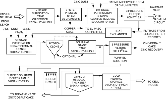
Schematic of continuous purification showing plant scale equipment details (from Ramachandran and Cardenas 1983). Copyright 1983. Reprinted with permission of The Minerals, Metals and Materials Society


A brief description of these procedures as applied to the laboratory and pilot plant data collected—described in Sects. 10.2 and 10.3—for the process development of an existing electrolytic zinc refinery is included in this section. Data collected from additional pilot plant runs—described in Sect. 10.3—were also used for the full-scale design of (a) settling and washing thickeners, (b) filtration of thickened slurries, and (c) treatment of the copper–cadmium cake for cadmium recovery using cementation as the main process step.
5 Commissioning and Trouble Shooting
5.1 Start-Up Organization (Harmsen 2013)
Prior to the commissioning of any plant, a start-up organization should be put together for the success of the project. There are various models for the start-up organization. Based on the scale of the start-ups, a model where the final production staff does the precommissioning, commissioning, and start-up works the best. It is also a good idea to have the researcher and the process engineer involved in the design, a process control specialist, and an analytical chemist as part of the start-up team. The start-up team should interact with the final operating staff regarding the complete process for a few months prior to the start-up date.
The start-up team should be headed by an experienced start-up leader with prior experience in major start-ups. He/she should be assisted by a qualified assistant to provide 24/7 leadership during the start-up.
5.2 Start-Up Preparation
The complete start-up team should go through a “potential” problem analysis and come up with answers ready to be implemented, if needed. This exercise will be helpful in developing a step-by-step procedure culminating in a complete start-up plan. This plan should be documented and distributed to all personnel involved in the start-up (Harmsen 2013). The next step is the start of the actual step-wise commissioning phase. Various steps of the commissioning phase are described below.
5.2.1 Commissioning
Commissioning is a staged process which starts when mechanical and electrical work is completed by the construction contractor . The terminology, scope, and sequence of the various stages can vary with the type and complexity of the plant and with the preferences and practices of the engineering group, technology supplier, and the operating company.
Generally, engineering is carried out by an outside firm, whereas the technology supplier can be part of the operating company as well as a separate organization.
A typical commissioning process comprises:
-
1.
Precommissioning
-
2.
Dry Commissioning
-
3.
Wet Commissioning
-
4.
Hot Commissioning
-
5.
Performance Testing
Typical activities may include:
-
1.
Precommissioning
-
Checking for conformity to design against drawings and specifications
-
Checking commissioning and operating procedures
-
Checking the status of all process equipment and associated electrical, controls, and instrumentation
-
Checking the status of all ancillary facilities including safety and fire protection/fighting; rescue and first aid; water; air; fuel; power supply/generation; steam generation; reagent storage and supply systems; tailings disposal systems; environmental control systems; laboratory facilities; and associated electrical, controls, and instrumentation
-
Flushing, cleaning, and drying
-
-
2.
Dry Commissioning
-
Planning and scheduling
-
Start-up and shut-down protocol
-
Checking piping and instrumentation against P&IDs
-
Calibration of instrumentation
-
Verification of control logic
-
Checking direction of motors
-
Functional checks of mechanical equipment and control systems, power and steam generation, environmental controls, and fire protection/fighting systems
-
Pressure testing
-
Operator training
-
Note: Dry commissioning of packaged facilities is best carried out in the supplier’s factory
-
-
3.
Wet Commissioning
-
Testing ore handling systems under load
-
Testing the operation of solution handling systems with water
-
Checking and rectifying leakages in equipment, tankage, piping, and ponds
-
Testing power and steam generation facilities
-
-
4.
Hot Commissioning
-
Introduction of feed materials
-
Operation of all facilities at low capacity under continuous closed loop conditions and increasing to design conditions of temperature and pressure
-
Monitoring for leakages in equipment, tankage, piping, and ponds, rectifying as required
-
Checking of instrumentation and controls, recalibrating as required
-
Implementation of sampling and analytical support activities
-
Commencing verification and updating of the process model with operating and analytical data
-
Implementation of environmental monitoring, controls, and reporting activities
-
Progressive increase of plant throughput to design conditions
-
-
5.
Performance Testing
-
Continuous operation for a specified period under design conditions
-
Verification of process and equipment efficiencies
-
Sampling and data gathering to verify throughput, production rate, product quality, quantity and composition of effluents, consumption of reagents, water, steam, power, and fuel
-
Compliance with process and equipment guarantees
-
5.2.1.1 Commissioning Team
The commissioning team is typically multidisciplinary and may include:
-
1.
A commissioning manager
-
2.
Process specialists
-
3.
Instrumentation/controls and electrical technicians
-
4.
Maintenance personnel
-
5.
Technology supplier’s representatives
-
6.
Equipment supplier’s representatives
-
7.
Operating personnel
The composition of the team typically varies as the program progresses through the various stages. Additional temporary personnel should be included during commissioning and the initial operating period to collect data, collect additional samples, and monitor the process while the regular operating crew is occupied in the mechanics of start-up.
5.2.1.2 Completion and Hand-Over
The point of completion of commissioning and hand-over from the engineering firm to the operating company varies and can occur at the end of wet commissioning, hot commissioning, or performance testing.
5.2.2 Trouble Shooting
Trouble shooting is carried out throughout the commissioning period . In each phase, punch lists (with priority) drawn up and rectification is undertaken before moving on to the next phase.
-
During precommissioning and dry commissioning , initially the problems will likely be related to functional issues with equipment, electrics and controls, and interfacing with supplier packages.
-
Wet commissioning issues will be more related to leakages and utility supply systems.
-
During hot commissioning , problems typically relate to equipment capacity, process design, product quality, environmental and safety issues, malfunction and calibration of instrumentation and control systems, additional leakages, achieving and controlling operating conditions (such as temperature and pressure), and early indication of failure of materials of construction program of testing alternatives.
-
Performance testing will reveal any capacity bottlenecks and provide a review of the problems rectified during hot commissioning and further information on materials of construction.
Some issues may require:
-
Additional design and construction work by the engineering firm
-
Further test work and process development by the technology supplier
-
Replacement of faulty or inadequate equipment items
-
Changing to alternative equipment designs
-
Additional environmental control systems
-
Modifications to ancillary facilities
-
Longer term materials of construction testing
In some cases, it may be necessary to engage specialist consultants to provide additional expertise.
5.3 Post Start-up Report
It is important to document—such as a daily log done 24/7—all the activities of a start-up of a plant. This should be done until a steady-state operation is attained over an accepted length of time and the operating personnel have a degree of comfort in running the plant. The report will have the following information:
-
1.
Start-up time.
-
2.
Deviations from design performance such as product quality, production rate, and utility needs.
-
3.
Deviations from design specifications and conditions.
-
4.
Critical analysis of the relation between deviations from expected performance.
The data so collected will be useful as:
-
1.
Reference document for the operating personnel—current and future.
-
2.
Errors and learning points can be used for making improvements in the design of the plant.
-
3.
On a long-term scenario, continual quality control improvements learnt from the start-up can be implemented on a company wide basis .
5.4 Commissioning and Trouble Shooting of Modernization of an Existing Electrolytic Zinc Plant
In Sects. 10.2–10.4, laboratory scale, pilot plant scale testing and data collection for design of a full-scale plant, respectively, were described in some detail. Based on the generic description of commissioning and troubleshooting in this section, the continuous leach and purification were brought on stream using the various commissioning steps outlined above.
The commissioning team consisted of:
-
1.
Start-up manager.
-
2.
Process specialist from the engineering company that designed the modernization plant.
-
3.
Research engineer and pilot plant manager involved in laboratory and pilot plant testing.
-
4.
Instrument/controls and electrical engineering staff from the existing plant.
-
5.
Maintenance engineering personnel from the existing plant.
-
6.
Equipment suppliers’ representatives.
-
7.
Operating personnel.
Preliminary meetings were held among the commissioning team to establish a line of action for start-up of the plant. The commissioning process steps listed at the start of this chapter were followed in a sequential order.
After completion of pre- and dry commissioning, wet commissioning was done as follows:
-
1.
Testing of solids handling systems under load for a short period of time. Since the leach tanks were yet to be tested, these solids were temporarily diverted to a storage system for later reuse. Load cell and other related instrument calibrations were confirmed.
-
2.
All solution handling systems such as leach tanks, purification tanks, storage tanks, pumps, and pipes were tested for leakage and fixed.
-
3.
All utilities, viz., power and steam generation facilities were tested for smooth and continuous operation.
Hot commissioning followed wet commissioning. This involved:
-
1.
Gradual introduction of feed materials, viz., zinc calcine and fume, pyrolusite ore (MnO2) for iron oxidation, spent electrolyte from electrowinning (EW) operations as the leachant, water, if needed, for pulp density adjustment, etc.
-
2.
Running of the leach section at reduced capacity to set up recycle streams—if it was part of the design and study effects of the same.
-
3.
Continued checking and fixing of leaks in the flow system.
-
4.
Implementation of all other aspects of hot commissioning outlined in this chapter.
-
5.
Progressive increase of plant throughput to attain design conditions.
-
6.
This operation took about 3 weeks and resulted in steady-state operations running at full design capacity.
-
7.
During this time, pre- and dry commissioning of the continuous purification was completed and the purification process run at low design rates to check the process chemistry for the removal of impurities.
-
8.
This was done by running the purified solution through a small test section of the electrowinning (EW) plant. The parameters evaluated included current efficiency, cathode quality, etc.
-
9.
Based on the feedback from the EW tests, the operating parameters for the purification steps were fine-tuned to get the desired impurities’ removal.
-
10.
The electrowinning testing helped in being able to run the purification steps close to design parameters in a relatively short time.
-
11.
Additional spare storage tanks and thickeners which were readily available were put to use for temporarily storing leach and purified solutions during the commissioning process. While doing so, it was decided to use two large 40,000 gal thickeners to store purified solutions, test the solution for impurities, and then proceed to the use of the solutions in electrowinning. This safety step played a major role in preventing any upsets in the EW step. Also, these thickeners helped to precipitate and remove gypsum from the purified solution. This step was useful in preventing major gypsum precipitation in the EW piping and cells thereby reducing cleaning and maintenance costs.
-
12.
During the commissioning steps, environmental monitoring, sampling procedures, and controls were set up and the reporting protocol established for use by the operating personnel.
-
13.
Also, sampling procedures and analytical support needs were established as per protocol.
-
14.
In summary, a continuous leaching and purification plant for combined treatment of calcine and fume in the electrolytic zinc industry for the first time was commissioned. Also, troubleshooting with its attendant solutions was completed in a timely manner .
5.5 Summary
In summary, this chapter describes the steps that were taken to successfully commission a new project from start to finish. This case study of the modernization of an existing plant was chosen as an example for its simplicity. A similar approach can be applied for any process whether or not developed from scratch through an innovative idea.
Lastly, this chapter describes how an innovative idea, new or improvement of an existing one, can be taken from concept to a successful operating process.
References
Harmsen, J. (2013). Industrial scale-up: A practical innovation guide from idea to commercial implementation (pp. 45–51). Oxford, England: Elsevier. ISBN 978-0-444-62726-1.
Kordoski, G. A. (2002). Copper recovery using leach/solvent extraction/electrowinning technology: Forty years of innovation, 2.2 million tonnes of copper annually. The Journal of the South African Institute of Mining and Metallurgy, 102, 445–450. November/December 2002.
Ramachandran, V., & Cardenas, R. I. (1983). Modernization of ASARCO’s Corpus Christi electrolytic zinc plant. In Proceedings of the 3rd International Symposium on Hydrometallurgy (pp. 971–984). Atlanta, GA: Publication of the Metallurgical Society of AIME. Retrieved March 1983.
Author information
Authors and Affiliations
Corresponding author
Editor information
Editors and Affiliations
Rights and permissions
Copyright information
© 2016 Springer International Publishing Switzerland
About this chapter
Cite this chapter
Ramachandran, R., Taylor, A. (2016). Conceptual Idea, Test Work, Design, Commissioning, and Troubleshooting. In: Lakshmanan, V., Roy, R., Ramachandran, V. (eds) Innovative Process Development in Metallurgical Industry. Springer, Cham. https://doi.org/10.1007/978-3-319-21599-0_10
Download citation
DOI: https://doi.org/10.1007/978-3-319-21599-0_10
Publisher Name: Springer, Cham
Print ISBN: 978-3-319-21598-3
Online ISBN: 978-3-319-21599-0
eBook Packages: Chemistry and Materials ScienceChemistry and Material Science (R0)