
Abstract
An RPD framework includes five components: The major connector, minor connectors, rests, direct retainers, and indirect retainers (in distal extension RPDs). A major connector combines all other components of an RPD so that the partial denture acts as one unit. Thus, functional loads can be distributed to all abutment teeth, and cross-arch stabilization can be provided. In addition, in distal extension RPDs, forces can be distributed between both the abutment teeth and the mucosa by unification of the direct retainers with the denture base.
Minor connectors provide rigidity and unification by joining other components of a framework to a major connector. Thus, the transmission of forces among the major connector, abutment teeth, and oral tissues can be achieved. And minor connectors act as a bracing component and maintain the path of insertion when they are located on guiding planes.
RPDs should be designed according to biomechanical and hygienic principles. Although design is a very important stage in the fabrication of the RPDs, unfortunately, dentists have a minimal input on this issue, and they leave it to the dental technician. This results in the common usage of the technician’s familiar designs (like the U-shaped maxillary major connector, considered the least preferable option). This chapter summarizes the major and minor connector designs, giving lots of samples for every Kennedy classification. Thus, dentists can easily create the most suitable design for their patients.
Access provided by Autonomous University of Puebla. Download chapter PDF
Keywords
- Major connector
- Minor connector
- Framework
- Removable denture
- Denture design
- Denture base
- RPD
- Removable partial denture
1 Definitions
- Cross-arch stabilization:
-
Resistance against dislodging or rotational forces obtained by using a partial removable dental prosthesis design that uses natural teeth on the opposite side of the dental arch from the edentulous space to assist in stabilization
- Guiding (guide) planes:
-
Vertically parallel surfaces on abutment teeth and/or dental implant abutments oriented so as to contribute to the direction of the path of placement and removal of a removable dental prosthesis
- Major connector:
-
The part of a partial removable dental prosthesis that joins the components on one side of the arch to those on the opposite side
- Minor connector:
-
The connecting link between the major connector or base of a partial removable dental prosthesis and the other units of the prosthesis, such as the clasp assembly, indirect retainers, occlusal rests, or cingulum rests
- Path of placement:
-
The specific direction in which a prosthesis is placed on the abutment teeth or dental implant(s)
2 Major Connectors
A removable partial denture (RPD) framework includes five components: major connector, minor connectors, rests, direct retainers, and indirect retainers (in distal extension RPDs) (Fig. 9.1).

The components of a removable partial denture framework: (a) major connector, (b) minor connectors, (c) rests (rest and minor connector on the right canine serve as indirect retainer), and (d) direct retainers
RPDs should be designed according to biomechanical and hygienic principles (see Chap. 4).
Although design is a very important stage in the fabrication of the RPDs, unfortunately, dentists have a minimal input on this issue, and they leave it to the dental technician. This results in the common usage and preference of the technician’s familiar designs (like the U-shaped maxillary major connector, considered the least preferable option). This chapter summarizes the major and minor connector designs, giving lots of samples for every Kennedy classification. Thus, dentists can easily create the most suitable design for their patients.
A major connector combines all other components of an RPD so that the partial denture acts as one unit. Thus, functional loads can be distributed to all abutment teeth, and cross-arch stabilization can be provided. In addition, in distal extension RPDs, forces can be distributed between both the abutment teeth and the mucosa by unification of the direct retainers with the denture base.
2.1 General Aspects of Major Connectors
All major connectors should have the following characteristics to function effectively and to protect the teeth and soft tissues:
-
1.
Major connectors should:
-
(a)
Be rigid
-
(b)
Have smooth and rounded line angles
-
(c)
Conform to anatomic structures
-
(d)
Not interfere with movable tissues
-
(e)
Not allow food entrapment
-
(f)
Not cover more tissue than necessary
-
(g)
Not use marginal gingiva for support
-
(h)
Not impinge on soft and hard tissue prominences or gingival tissue during placement, removal, or function
-
(a)
-
2.
Borders of a major connector should:
-
(a)
Run parallel to the gingival margins of the remaining teeth in both arches (Figs. 9.2 and 9.3).
Fig. 9.2 
All major connectors’ borders should run parallel to the gingival margins of the remaining teeth. Borders of a mandibular major connector should be placed at least 3–4 mm away from the free gingival margins
Fig. 9.3 
Borders of a major connector should not be placed on the free gingival margin, instead running away from the margins (at least 6 mm). Otherwise, it should be extended as a plate
-
(b)
Be placed at least 3–4 mm away from the free gingival margins in the mandibular arch (Fig. 9.2). Otherwise, the major connector should cover the lingual surfaces of the teeth as a plate. On the anterior teeth, the plate should cover the cingula but not be higher than the middle third of the teeth, except to cover the interproximal spaces at the contact points. On the posterior teeth, the plate should end at the height of the contour in both arches.
-
(c)
Be placed at least 6 mm away from the free gingival margins in the maxillary arch. Otherwise, the major connector should cover the lingual surfaces of the teeth as a plate (Fig. 9.3).
-
(d)
Not end on the crest of rugae or at the free gingival margin (Fig. 9.4).
Fig. 9.4 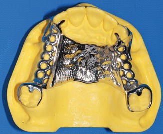
The rugae should be replicated anatomically, and borders of major connectors should not end on the crest of rugae
-
(e)
Cross the maxillary midline at right angles, not diagonally.
-
(f)
Be beaded to increase the adaptation, to prevent debris from collecting beneath the major connector, and to minimize the casting shrinkage in all maxillary major connectors (0.5–1 mm wide and deep) (Fig. 9.5). Beading is not necessary in the mandibular major connector.
Fig. 9.5 
Bead lines are used in all maxillary major connectors, not in mandibular major connectors
-
(a)
-
3.
Relief is not required except for a palatal torus or prominent median palatal suture area in the maxillary major connectors, but it is often necessary between the rigid metal surfaces and the underlying soft tissues in the mandibular major connectors.


2.2 Maxillary Major Connectors
-
1.
Anteroposterior palatal strap
-
(a)
It can be used for Kennedy Class I, II, III, IV, and V partially edentulous arches (Fig. 9.6a–d).
Fig. 9.6 
(a–d) An anteroposterior palatal strap major connector can be a desirable choice for all maxillary arches except Kennedy-Applegate Class VI arches having short edentulous space. While anterior and lateral straps should be 6–8 mm wide, posterior strap should be 4 mm wide. The design example shown in (d) can also be used in Kennedy-Applegate Class V cases having weak anterior abutment. In distal extension bases, wrought wire retentive arms are indicated where clasp tips lie in front of the axis of rotation. For example, in the cases shown in Fig. 9.6a, a wrought wire clasp can be used on the right canine abutment tooth
-
(b)
It is structurally rigid with minimum bulk.
-
(c)
The anterior and lateral straps should be 6–8 mm wide. The posterior palatal strap can be 4 mm wide to increase patient comfort.
-
(d)
The palatal opening should be 15 mm or more in an anteroposterior dimension.
-
(e)
The anterior strap should not be placed beyond the most anterior rests.
-
(f)
The posterior strap should be placed as far back as possible but should not be in contact with the tissues of the movable soft palate.
-
(g)
When the presence of an inoperable torus that ends posteriorly 6–8 mm from the anterior of the junction of the hard and soft palates, an anteroposterior palatal strap can be used.
-
(a)
-
2.
Palatal strap
-
(a)
It is used in Kennedy Class III and VI partially edentulous arches if edentulous spaces are short (Fig. 9.7).
Fig. 9.7 
A palatal strap major connector can be used in Kennedy Class III and Kennedy-Applegate Class VI arches having short edentulous spaces. Its anteroposterior dimension should be minimum of 8 mm
-
(b)
The rigidity provided by a palatal strap is usually adequate if the anteroposterior dimension of a strap is a minimum of 8 mm.
-
(c)
If there is a large torus, palatal strap should not be used.
The anteroposterior palatal bar and the palatal bar mentioned in many textbooks are variations of the anteroposterior palatal strap and the palatal strap major connectors. They should be bulky in order to be rigid, and thus they are generally unacceptable for many patients and not recommended.
-
(a)
-
3.
Palatal plate
-
(a)
It is essentially used in Kennedy Class I partially edentulous arches where six or less anterior teeth remain, the abutments are periodontally weakened, and/or the support from the residual ridges is poor (Fig. 9.8a).
Fig. 9.8 
(a, b) When maximum tissue support is necessary, a palatal plate major connector can be used. Posterior part of the major connector can be formed as a gridwork design. Wrought wire retentive arms can also be used on the canine abutments
-
(b)
It is structurally rigid.
-
(c)
It covers one half or more of the hard palate.
-
(d)
The posterior border extends to the junction of the hard and soft palates. The posterior palatal seal that is used with complete dentures should not be utilized unless the posterior part is made of acrylic resin as seen in Fig. 9.8b; instead, a slight mechanical seal may be formed by ensuring the presence of a bead line along the posterior border of the major connector.
-
(e)
If there is a large torus, palatal plate should not be used.
-
(f)
Three forms of the palatal plate can be used for different cases:
-
1.
It can cover two-thirds of the palate. The anterior border does not extend beyond the most anterior rests.
-
2.
The posterior part of the palatal plate can be formed as a gridwork design with the possibility of adding acrylic resin. This form allows for future relining (Fig. 9.8b).
-
3.
Linguoplating can be used for indirect retention or subsequent replacement of natural teeth.
Modified palatal plate connector: It is used in Kennedy Class II partially edentulous arches. Anteroposterior dimension and form is done as palatal strap and continued backward, ending with a butt joint at the entrance to the hamular notch. The posterior border may not be extended to the junction of the hard and soft palates (Fig. 9.9).
Fig. 9.9 
A modified palatal plate major connector used in Kennedy Class II cases
-
1.
-
(a)
-
4.
U-shaped or horseshoe
-
(a)
It is not structurally rigid, especially for the Kennedy Class I and II partially edentulous arches.
-
(b)
It is only used in cases with a prominent median suture line and if an inoperable torus extends to the posterior limit of the hard palate (Fig. 9.10). It can be used when the patient insists on the use of her/his old denture’s design, which is U-shaped, or when he/she thinks they cannot tolerate the posterior portion of the major connector. When it is used, the thickness of the framework should be increased if maximal rigidity is desired. This can be accomplished by the use of two layers of pattern wax when the framework is made.
Fig. 9.10 
A “U-shaped” or horseshoe major connector. Its use is limited because the rigidity is not sufficient
Rigidity is a very important factor which should be taken into consideration for major connectors because it has been shown that the rigid major connectors decrease both RPD and abutment tooth movement under loading. As described above, a major connector requires a minimum size for rigidity. Therefore, it is not recommended to reduce the metal framework for all types of major connectors.
-
(a)


2.3 Mandibular Major Connectors
-
1.
Lingual bar
-
(a)
It is structurally rigid if it is designed to a height of 4 mm and a thickness of 2 mm and is half pear-shaped in cross section with the thin edge toward the teeth (Fig. 9.11).
Fig. 9.11 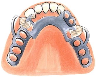
If there is at least 7 mm vertical distance between the floor of the mouth and the gingival margins of the teeth when the tip of the patient’s tongue is touching the anterior part of the palate, a lingual bar major connector can be used
-
(b)
The superior border of the bar should be 3 mm below the gingival margins. Therefore, it requires at least 7 mm of vertical space between the floor of the mouth and the gingival margins of the teeth when the tip of the patient’s tongue is touching the anterior part of the palate.
-
(c)
It cannot be used when a large inoperable torus exists (Fig. 9.12).
Fig. 9.12 
In cases having large inoperable lingual torus, a lingual plate major connector should be used
-
(a)
-
2.
Lingual plate
-
(a)
It is structurally rigid.
-
(b)
It is an extended version of a lingual bar with a thin metal plate. The metal plate should cover the cingulum of the anterior teeth and the superior border must be scalloped (Fig. 9.13).
Fig. 9.13 
The metal plate should cover the cingulum of the anterior teeth when a lingual plate major connector is used
-
(c)
When interproximal spaces exist between the anterior teeth, “stepbacks” can be designed to avoid display of metal.
-
(d)
It should have a terminal rest at each end regardless of the need for indirect retention.
-
(e)
It can be used in the presence of inoperable mandibular tori.
The Kennedy bar (double lingual bar/continuous bar), which is indicated when the axial alignment of the anterior teeth needs excessive blockout for the lingual plate and wide diastemata exist, and the labial bar, which is indicated when excess lingually inclined anterior teeth exist, are mentioned in many textbooks. Both of them can create a food trap and can be disturbing to patients. Thus, they are not a practical solution, either esthetically or functionally, and are not mentioned in this chapter.
-
(a)


In case the interocclusal distance is too limited to set up regular artificial teeth or due to existing deep-bite (severe vertical overlap), occlusal or palatal surfaces may be added to the framework design which can be engaged with veneering materials. This option allows easy handling of the posterior edentulous space and eliminates the risk of acrylic base fracture (Fig. 9.14). Additionally in the presence of short spaces, insufficient room to set up artificial teeth can be closed only with metal if it does not cause esthetic problem. This will prevent food impaction and the migration of the teeth (Fig. 9.15).

An interim removable partial denture with metal occlusal surface. Metal occlusal or palatal surfaces can be used in cases having insufficient interocclusal distance and severe vertical overlap

If there is a short edentulous area which is not in the esthetic zone, it can be filled with metal only to prevent food impaction and the migration of the teeth
3 Minor Connectors
3.1 General Aspects of Minor Connectors
-
1.
Minor connectors provide rigidity and unification by joining other components of a framework to a major connector. Thus, the transmission of forces among the major connector, abutment teeth, and oral tissues can be achieved.
-
2.
Minor connectors act as a bracing component and maintain the path of insertion when they are located on guiding planes.
-
3.
Minor connectors should be rigid (except the fourth type) and placed so as not to irritate the surrounding tissues.
3.2 Types of Minor Connectors
-
1.
Minor connectors that join clasp assemblies to major connectors. As they may be attached to the clasps, they can also be a separate entity
-
(a)
Mostly, they are located on guiding planes or surfaces. Sometimes, it is necessary to put them on a tooth surface adjacent to another tooth. In this situation, it should be positioned in the associated lingual embrasure.
-
(b)
When it is formed as a separate entity, it should be approximately 1–1.5 mm thick, tapering both occlusally and facially. It is shifted slightly toward the lingual side to increase rigidity and enhance reciprocation (Fig. 9.16).
Fig. 9.16 
If a proximal plate minor connector can be formed as a separate entity, it is shifted slightly toward the lingual side
-
(c)
The guide (proximal) plate minor connector should cover about half the distance of the abutment tooth buccolingually (between tips of buccal and lingual cusps) and two-thirds the distance of the tooth occlusogingivally. It is effective to prepare a guide plane as close to the gingival margin as possible to reduce the plaque accumulation (Figs. 9.16 and 9.17).
Fig. 9.17 
A proximal plate minor connector should be placed on the guiding plane covering about two-thirds of the tooth occlusogingivally
-
(d)
In distal extension RPDs, the proximal plate is in contact with the entire guiding plane initially, but physiologic relief is necessary at the framework try-in. In tooth-supported RPDs, guiding plane preparation and proximal plates are generally longer, and physiologic relief is not necessary. An elongated proximal plate that is parallel to the path of insertion may compensate for the loss of retention when an adequate guiding plane cannot be prepared.
-
(e)
If tooth surfaces are parallel to the path of placement, preparation of the guiding plane is not necessary. (Preparation of the guiding planes on the abutment teeth is described in chapter 7.)
-
(a)
-
2.
Minor connectors that join indirect retainers or auxiliary rests to major connectors
-
(a)
They should be positioned in embrasures and should form right angles with the major connector, and junctions should be rounded. Although one study proposed to place minor connector on the center of the lingual aspects of the maxillary abutment tooth to reduce the amount of gingival tissue coverage, more randomized clinical studies are needed to change the classical knowledge.
-
(a)
-
3.
Minor connectors that join denture bases to major connectors
-
(a)
They can be constructed in different designs such as mesh design, ladderlike design, loop design, or metal base with different retentive elements (such as bead, nailhead). Metal bases can be used instead of acrylic resin bases in tooth-borne removable partial dentures where the short edentulous spaces exist (Fig. 9.18). Large openings in a retention design are generally more satisfactory than a mesh design which may result in further weakening of the resin (Fig. 9.19). Additionally, Ohkubo et al. recommended that the three structural designs which are superior to conventional design may also be considered along with the conventional designs.
Fig. 9.18 
Tissue surface can also be fabricated with metal in cases where tissue support and future relining are not necessary
Fig. 9.19 
Large-opening gridwork designs such as ladderlike and loop designs (right) are more preferable than mesh design (left) considering the acrylic retention. But the thickness of these designs can complicate artificial tooth setting
-
(b)
In Kennedy Class I and II mandibular arches, the minor connector should extend about two-thirds the length of the edentulous ridge but should not be placed on the ascending portion of the ridge. It should be extended on both buccal and lingual surfaces (Fig. 9.20).
Fig. 9.20 
In mandibular distal extension removable partial dentures, gridwork minor connector should not be placed on the ascending portion of the ridge
-
(c)
In Kennedy Class I and II maxillary arches, they should be extended as far as possible posteriorly, and the junction of major and minor connectors should be located 2 mm medially from an imaginary line that would come into contact with the palatal surfaces of artificial teeth.
-
(d)
In free-end saddle partially edentulous cases, they must be finished with a “cast stop.” Altered cast impression procedures result in an elevated cast stop from the residual ridge. The autopolymerizing acrylic resin can be added to compensate for this gap (Fig. 9.21a–c).
Fig. 9.21 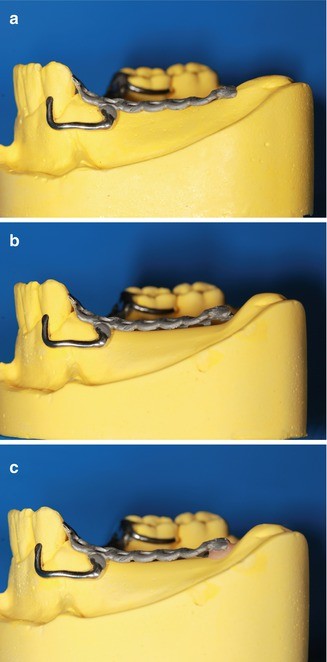
(a–c) Metal cast stop can be modified with self-cure acrylic resin, if an altered cast impression has been performed
-
(e)
Relief under the minor connector should be started 1.5–2 mm away from the abutment tooth. Thus, metal/tissue contact can be created in this area.
-
(f)
A butt joint should be used to design the resin-metal interface (finishing line). The finishing line junction with the major connector should take the form of an angle not greater than 90°, therefore being somewhat undercut.
-
(a)
-
4.
Minor connectors that serve as approach arms for vertical projection/bar-type clasps
These minor connectors support the clasps and do not need to be rigid (Fig. 9.1).
Different study results showed that there was insufficient evidence to determine whether one design was better or worse than another regarding major/minor connectors and direct retainers in mandibular distal extension RPDs. Removable partial dentures will not have any harmful effects on the remaining teeth and periodontal tissues if they are properly designed and oral hygiene is checked regularly.


Bibliography
Abt E, Carr AB. Worthington HV Interventions for replacing missing teeth: partially absent dentition(Review). Cochrane Database Syst Rev. 2012;2:1–52.
Akaltan F, Kaynak D. An evaluation of the effects of two distal extension removable partial denture designs on tooth stabilization and periodontal health. J Oral Rehabil. 2005;32:823–9.
Ben-Ur Z, Mijiritsky E, Gorfil C, Brosh T. Stiffness of different designs and cross-sections of maxillary and mandibular major connectors of removable partial dentures. J Prosthet Dent. 1999;81:526–32.
Bohnenkamp DM. Removable partial dentures. Dent Clin N Am. 2014;58:69–89.
Carr AB, Brown DT. McCracken’s removable partial prosthodontics. 12th ed. Mosby: St Louis Missouri; 2011.
Chow TW, Clark RKF, Clarke DA. Improved designs for removable partial dentures in Kennedy Class IV cases. Quintessence Int. 1988;19:797–800.
Dunny JA, King GE. Minor connector designs for anterior acrylic resin bases: a preliminary study. J Prosthet Dent. 1975;34:496–502.
Green LK, Hondrum SO. The effect of design modifications on the torsional and compressive rigidity of U-shaped palatal major connectors. J Prosthet Dent. 2003;89:400–7.
Hosman HJM. The influence of clasp design of distal extension removable partial dentures on periodontium of the abutment teeth. Int J Prosthodont. 1990;3:256–65.
Itoh H, Baba K, Aridome K, Okada D, Tokuda A, Nishiyama A, Miura H, Igarashi Y. Effect of direct retainer and major connector designs on RPD and abutment tooth movement dynamics. J Oral Rehabil. 2008;35:810–5.
Jorge JH, Giampaolo ET, Vergani CE, Machado AL, Pavarina AC, Cardoso de Oliveira MR. Clinical evaluation of abutment teeth of removable partial denture by means of the Periotest method. J Oral Rehabil. 2007;34:222–7.
Kapur KK, Deupree R, Dent RJ, Hasse AL. A randomized clinical trial of two basic removable partial denture designs. Part I: Comparisons of five-year success rates and periodontal health. J Prosthet Dent. 1994;72:268–82.
Keyf F. Frequency of the various classes of removable partial denture and selection of major connector and direct/indirect retainer. Turk J Med Sci. 2001;31:445–9.
LaVere AM, Krol AJ. Selection of a major connector for the extension-base removable partial denture. J Prosthet Dent. 2005;94:207–8.
Loney RW. Removable partial denture manual: 2011. http://removpros.dentistry.dal.ca/RemovSite/Manuals_files/RPD%20Manual%2011.pdf.
Ohkubo C, Abe M, Miyata T, Obana J. Comparative strengths of metal framework structures for removable partial dentures. J Prosthet Dent. 1997;78:302–8.
Ohkubo C, Kurtz KS, Suzuki Y, Hanatani S, Abe M. Comparative study of maxillary complete dentures constructed of metal base and metal structure framework. J Oral Rehabil. 2001;28:149–56.
Phoenix RD, Cagna DR, Defreest CF. Stewart’s clinical removable partial prosthodontics. 4th ed. Chicago: Quintessence Publishing; 2008.
Pienkos TE, Morris WJ, Gronet PM, Cameron SM, Looney SW. The strength of multiple major connector designs under simulated functional loading. J Prosthet Dent. 2007;97:299–304.
Polychronakis N, Sotiriou M, Zissis A. A survey of removable partial denture casts and major connector designs found in commercial laboratories, Athens, Greece. J Prosthodont. 2013;22:245–9.
Pun DK, Waliszewski MP, Waliszewski KJ. Survey of partial removable dental prosthesis (Partial RDP) types in a distinct patent population. J Prosthet Dent. 2011;106:48–56.
Radford DR, Walter JD. A variation in minor connector design for partial dentures. Int J Prosthodont. 1993;6:50–4.
Sato Y, Hosokawa R. Proximal plate in conventional circumferential cast clasp retention. J Prosthet Dent. 2000;83:319–22.
Shifman A, Ben-Ur Z. Prosthodontic treatment for the Applegate-Kennedy class V partially edentulous patient. J Prosthet Dent. 1996;76:212–8.
Shimura Y, Wadachi J, Nakamura T, Mizutani H, Igarashi Y. Influence of removable partial dentures on the formation of dental plaque on abutment teeth. J Prosthodont Res. 2010;54:29–35.
Stratton RJ, Wiebelt FJ. An atlas of removable partial denture design. Chicago: Quintessence Publishing Co; 1988.
The glossary of prosthodontics terms. J Prosthet Dent. 2005;94:10–92.
Author information
Authors and Affiliations
Corresponding author
Editor information
Editors and Affiliations
Rights and permissions
Copyright information
© 2016 Springer International Publishing Switzerland
About this chapter
Cite this chapter
Şakar, O. (2016). Major and Minor Connectors. In: Şakar, O. (eds) Removable Partial Dentures. Springer, Cham. https://doi.org/10.1007/978-3-319-20556-4_9
Download citation
DOI: https://doi.org/10.1007/978-3-319-20556-4_9
Publisher Name: Springer, Cham
Print ISBN: 978-3-319-20555-7
Online ISBN: 978-3-319-20556-4
eBook Packages: MedicineMedicine (R0)