
Abstract
This chapter addresses the problem of determining stowage plans for containers into a ship, which is the so-called master bay plan problem (MBPP). As a novel issue and variant of MBPP, in the present work we consider the stowage of hazardous containers that follows the principles included in the segregation table of the International Maritime Dangerous Goods (IMDG) Code. Formally, the MBPP consists in determining how to stow a set of n containers, split into different groups, according to their size, type, class of weight and destinations, into a set of m available slots, that are locations either on the deck or in the stow, of predetermined bays of a containership. Some structural and operational constraints, related to both the containers and the ship, have to be satisfied. The need of stowing dangerous goods implies to take into account additional constraints to be verified in each slot concerning the safety of the whole cargo, for which dangerous goods are categorized into different types and forced to be stowed away from incompatible ones. We face such variant of MBPP on the basis of its relationship with the bin packing problem, where items are containers and the bins are sections of the ship available for the stowage of hazardous containers. In particular, following a step by step procedure for properly loading all containers on board, we show how the segregation rules derived from the IMDG Code impact on the available slots of the bins. A real life case study is reported.
Access provided by Autonomous University of Puebla. Download chapter PDF
Keywords
- Hazardous containers
- International Maritime Dangerous Goods Code
- Master bay plan problem
- Bin packing
- Combinatorial optimization
1.1 Introduction
Nowadays, mainly due to the increase in the shipping business and the phenomenon of naval gigantism, the sea is more and more becoming the main commercial channel. Following this trend, a still increasing number of works have been recently proposed in the literature focusing on the performances of maritime terminals, whose activities are pivotal functions for operating supply chains efficiently. A recent overview of relevant literature about maritime terminal operations is provided in Stahlbock and Voss [1].
In this context, it is not surprising that container handling problems, and particularly the container loading aspects, have been dealt with frequently in the operations research literature (see, e.g., [2, 3], for surveys).
In this chapter, we focus our analysis on the quay and ships activities; more precisely, we devote our attention to the problem of determining stowage plans for containers into a ship, which is the so-called master bay plan problem (MBPP). Readers can find a detailed description of MBPP together with its main constraints in Ambrosino et al. [4]. MBPP is an NP-Hard problem [5], and a number of heuristics have been developed for efficiently facing this problem, usually applied to large size instances. Some heuristic methods for MBPP are compared in Ambrosino et al. [6].
Formally, the MBPP consists in determining how to stow a set of n containers of different size, type, class of weight and destinations, into a set of m available slots, that are locations either on the deck or in the stow, of predetermined bays of a containership. Some structural and operational constraints, related to both the containers and the ship, have to be satisfied. The aim is the operational efficiency of a port, depending on the loading and unloading containers’ operations, and the minimization of the time that a ship is at the berth. It is also required to prevent damages to the goods, the ship, its crew and its equipment and the marine environment.
Regarding this, note that up to 8 % of the containers to be loaded into a ship consists of hazardous containers, that is containers carrying dangerous goods, such as solids, liquids, or gases, that can harm people, other living organisms, property, or the environment.
As a novel issue and variant of MBPP, in the present chapter we consider the stowage of hazardous containers that follows the principles included in the segregation table of the International Maritime Dangerous Goods (IMDG) Code, as it will be explained in the next section. In particular, the need of stowing dangerous goods implies to take into account additional constraints to be verified in each slot concerning the safety of the whole cargo, for which dangerous goods are categorized into different types and forced to be stowed away from incompatible ones. Note that, according to the ship certificate, hazardous containers can be stowed only in some slots in the hold of the ship.
Usually the MBPP involves loading decisions at a port which should take into account the possible loading operations at the next ports in the ship route; this means that stowing plans are determined for each port considering the sequence of ports that must be visited by the ship. Only few papers deal with the placement of containers into a containership on a multi-port journey. For instance, Imai et al. [7] present a unified approach for taking into account the route planning problem from both the liner and the terminal manager point of view. Different mathematical programming models are presented and evaluated throughout an extensive computational experimentation in Ambrosino et al. [8]. Delgado et al. [9] present a constraint programming approach for dealing with multi-port routes, focusing the attention on the loading problem at each departing port. Here, we are involved with the loading process of both standard and hazardous containers at a terminal: the stowage plan is defined for loading the containers that in a given port must be loaded and shipped to the different ports visited by the ship; note that the loading plan is not really affected by what happens in the next ports.
In particular, we present a methodological approach for facing the proposed MBPP with hazardous containers based on its relation with the bin packing problem, where items are containers and the bin is a slot of the ship. Relations between MBPP and BBP have been previously presented in Sciomachen and Tanfani [10] and in Zhang et al. [11], where the authors used the same similarity for packing containers into single ship bays. Sciomachen and Tanfani [12] extended the connection between MBPP and 3D-BPP proposed in the previous work by considering the loading pattern for maximizing the productivity of the quay operations at a maritime terminal thus balancing the crane work load. Recently, De Queiroz and Miyazawa [13] focus on the load balancing problem. For a review and classification of cutting and packing problems, the reader can refer to Wäscher et al. [14].
The way in which the international conventions about maritime transportation of dangerous goods impacts on the available slots of the ship, that is the bin, is explained in detail in Sect. 1.3. After the presentation of a real sized case study, reported in Sect. 1.4, in the last section of the chapter we derive some conclusions and outlines for future works.
1.2 International Regulations for Maritime Transport of Dangerous Goods
Today, the international law related to the maritime transport of dangerous goods issue includes many international treaties and codes. All of them have been written under the supervision of the International Maritime Organization (IMO). Note that, as agency of the United Nations, IMO sets internationally valid standards for safety, security and environmental performance of international shipping. Its aim is to create a high level playing-field so that ship operators can’t address their financial interests by simply cutting costs and reducing safety, security and environmental performances.
The first Convention to mention is the International Convention for Safe Containers (CSC), entered into force in 1972 after the rapid increase in the use of freight containers for the consignment of goods by sea and the development of specialized container ships, seen in the 1960s. So IMO, in co-operation with the Economic Commission for Europe, developed the Convention which had two goals. The first one is to assure a high level of safety of human life in the transport and handling of containers by providing test procedures and related strength requirements. The second goal is to facilitate the international transport of containers by providing uniform international safety regulations, equally applicable to all modes of surface transport. In this way, proliferation of divergent national safety regulations can be avoided.
Very important is also the International Convention for the Prevention of Pollution from Ships (MARPOL), adopted on 1973 and entered into force on 1983. This is the main international regulation related to the prevention of marine pollution caused by ships and due to accidental or operational causes; the first aim of MARPOL is preventing and/or minimizing pollution of the marine environment. Strictly related to the topic of the present chapter, the most important part is the Annex III, which contains general requirements for packing, marking, labelling, documentation, stowage, quantity limitations, exceptions and notifications, in case of substances carried in packaged form.
The SOLAS Convention is the most important treaty concerning the safety of merchant ships. The first version was written in 1914, after the Titanic disaster, but the last and official version was adopted in 1974. The main aim of the SOLAS Convention is to specify minimum standards for construction, equipment and operation of ships. Flag States are responsible for ensuring that ships under their flag comply with those requirements, and as a proof the Convention prescribes a number of certificates which ships and operators have to provide. For the purpose of this work, we have to focus on Chap. 7, which provides regulations about: (a) carriage of dangerous goods in packaged form; (b) construction and equipment of ships carrying dangerous liquid chemicals in bulk; (c) construction and equipment of ships carrying liquefied gases in bulk and gas carriers; (d) special requirements for the carriage of packaged irradiated nuclear fuel, plutonium and high-level radioactive wastes on board ships. Note that this chapter makes mandatory the International Maritime Dangerous Goods Code (IMDG Code), developed by IMO.
The IMDG Code has been edited as a uniform international reference for the transport of dangerous goods by sea, covering such matters as packing, container traffic and stowage, with particular reference to the segregation of incompatible substances. Since its adoption by the fourth IMO Assembly in 1965, the IMDG Code has been modified many times to be up-to-date with the ever-changing needs of industry. Amendments which do not affect the principles upon which the Code is based may be adopted by the MSC (Maritime Security Council), allowing IMO to respond to transport developments in reasonable time. The Code classifies dangerous goods into different classes, with the purpose of underlining, defining and describing main characteristics and properties of the substances, material and articles which would fall within each class or division. General provisions for each class or division are given. Individual dangerous goods are listed in the Dangerous Goods List, with the class and any specific requirements. In particular, all substances and articles subject to the provisions of this Code are assigned to one of the classes 1–9 according to the hazard (or the most predominant of the hazards) they present. These nine classes are reported in Fig. 1.1.

The nine classes of dangerous goods
Above all the aspects faced by the IMDG Code, we have to underline the contents of Chap. 7, that is the segregation principles. Those are the guidelines which have to be followed by operators and carriers, in order to assure safety and security in every step of the transportation chain.
In fact, for their chemical properties, many substances are incompatible, continuously, because they could react mutually bringing to damages due even to explosions, production of noxious or mortal gases and so on. For these reasons, a minimum distance has to be kept among these substances.
For this purpose, the Code provides a number of segregation rules, based on the properties of substances grouped in Classes and Divisions and listed into the Dangerous Goods List. Each relation between Classes is listed into the segregation table, reported in Fig. 1.2. Into the segregation table it is possible to identify specific segregation principles that must be followed for the stowage of every substance, if the cargo includes other harmful substances which are incompatible with the first. Furthermore, the IMDG Code provides different rules in relation to the type of cargo containers used, which could be open-top containers or standard closed containers.

The segregation table
In particular, the following four segregation principles are the most meaningful ones in terms of definition of stowage plans:
-
1.
“Away from”;
-
2.
“Separated from”;
-
3.
“Separated by a complete compartment from”;
-
4.
“Separated longitudinally by an intervening complete compartment or hold from.”
These principles will be investigated in more detail in the next section devoted to the definition of stowage planning problems and its related rules.
1.3 The Stowage Planning Problem and the Rules for Dangerous Goods
To give an idea of how a stowage plan is defined, let us consider the basic structure of a containership and its sections, depicted in Fig. 1.3 [4]; it consists of a given number of locations, which generally have a standard size of 8 feet (8′) in height, 8′ in largeness and 20′ in depth, corresponding to one TEU (Twenty Equivalent Unit). Each location is identified by three indices, namely bay, row and tier, each one consisting of two numbers that give its position with respect to the three dimensions.

Sections of a standard containership
Note that the address number of the ship locations depends on the numerical system adopted by each maritime company. Generally, each 20′ bay is numbered with an odd number, i.e. bay 01, 03, 05, etc., while two contiguous odd bays conventionally originate one even bay, used for the stowage of 40′ containers, i.e. bay 02 = bay 01 + bay 03 (see Fig. 1.3). As far as the row index, the ship locations have an even number if they are located on the left side, i.e. row 02, 04, 06, and an odd number if they are located on the right side, i.e. row 01, 03, 05, etc. Finally, for the tier index, the levels are numbered from the bottom of the hold to the top with even number, i.e. tier 02, 04, 06, etc., while in the upper deck possible numbers are 82, 84, 86, etc. Note that the tier numbers allow to distinguish in the final stowage plan the containers stowed in the hold from those in the upper deck.
In this chapter, we refer to the connection between MBPP and the 3D-BPP presented in Sciomachen and Tanfani [10], in which the exact branch-and-bound algorithm proposed by Martello et al. [15] is used for solving 3D-BPP instances. More precisely, we consider the MBPP as a three-dimensional orthogonal bin packing problem.
Formally, given a set of n rectangular-shaped items, each one characterized by width w j , height h j , and depth d j , j = 1, …, n, and a set of three-dimensional bins, having width W, height H, and depth D, 3D-BPP consists of orthogonally packing all items into the bins. As in most cutting and packing problems [16] we assume that the considered bins are sufficient in number and size for containing all items, and the objective is either to minimize the number of bins or maximize the values of the loaded items or minimize the loading time.
The connection between 3D-BPP and MBPP implies that items are containers and the ship is the bin; however, note that the shape of a ship is different from a standard six-face solid that is utilized as the bin in 3D-BPP. Therefore, as in Sciomachen and Tanfani [10], in this chapter we assume the ship to be the bin and split it into different regular sections in order to be able to consider the above and below deck spaces, the bow and the stern as separate components. In this way, each section of the ship has a parallelepiped shape. In particular, for the purpose of the present work let us assume that four sections, i.e. bins, are considered for stowing dangerous containers; these bins, namely B1, B2, B3 and B4, are highlighted in Fig. 1.3. Further, note that all containers to be loaded, representing the items, are standard in size that is either 20′ or 40′ in length.
It is worth mentioning that we do not consider those slots in bays, rows and tiers where it is not possible to stow hazardous containers for safety reason, which are usually the most external bays and lowest tiers. Further, note that many maritime companies inhibit for stowage the whole external bays and those closest to the machineries and cabins of the crew; these are bays 43 and 45 in Fig. 1.3.
Each one of sections B i , i = 1, …, 4, can be hence considered as a bin and filled by following the main frame of the exact branch-and-bound algorithm for the 3D-BPP proposed by Martello et al. [15]; in that algorithm, it is assumed that items cannot be rotated, and are packed with each edge parallel to the corresponding edge of the bin. These assumptions are applicable to MBPP too. In particular, they are required for the definition of stowage plans since containers have to be stowed only in one orthogonal direction, one above the other in a stack.
In Sciomachen and Tanfani [10] the authors adapted the above-mentioned enumerative algorithm for 3D-BPP for finding feasible solutions for MBPP.
Here our goal is to show how the segregation rules derived from the IMDG Code impact on the available slots of the considered bins. In particular, we determine stowage plans filling simultaneously each one of the four bins, in such a way to satisfy the main structural constraints of the problem related to both the containers and the ship and the IMDG Code rules described in Sect. 1.2. In particular, having in mind the main segregation principles for dangerous goods presented in Sect. 1.2, let us define them in terms of stowage rules to be satisfied for loading the items, that is the containers, in the bin, that, for example referring to Fig. 1.3, could be the portion of the ship consisting of bays from 43 to 17 in the hold and of bays from 43 to 13 in the deck, that is bins B2 and B1, respectively. Further, let us focus on the segregation principles 2–4, concerning stowage rules for containerized items. Note that we always refer to closed containers.
-
Principle 2: Separated from.
This principle means that dangerous containers can never be put in the same stack (vertical line), unless they are separated by a deck, while can be stowed horizontally separated by one container space. Under deck this distances is not necessary if there is a bulkhead; for example, given two hazardous containers that have to respect the separation principle 2, referring to Fig. 1.3, if one container is stowed in bay 23, row 05 and tier 02, the other one can be stowed in the same row, same tier and bay 25 thanks to bulkhead.
Figure 1.4 shows the implementation of this principle with respect to the available slots for stowing hazardous containers in the considered bin, both in the deck and in the hold, that is either B1 or B2, according to the longitudinal and cross sections of the ship.
Fig. 1.4 
Implementation of the second segregation principle for dangerous goods
In Figs. 1.4, 1.5, and 1.6 the slot coloured light represents a location where a hazardous container has been already stowed, while the slots coloured dark are those locations that are consequently forbidden for stowing other hazardous containers.
Fig. 1.5 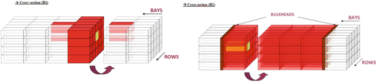
Implementation of the third segregation principle in the deck (B1) and the hold (B2)
Fig. 1.6 
Implementation of the fourth segregation principle in the deck (B1) and the hold (B2)
-
Principle 3: Separated by a complete compartment from.
This principle means that dangerous containers can never be put in the same stack (vertical line), same hold or above the same hold. Thus, containers in the hold must be separated by a bulkhead (see Fig. 1.5); for example, given two hazardous containers that have to respect the separation principle 3, referring to Fig. 1.3, if one container is stowed in bay 41, row 05 and tier 02, the other one cannot be stowed in any location (both of the deck and the hold) in the bays 41 and 43 (i.e., there is a bulkhead separating bay 41 and bay 39 in the hold).
Containers on the deck must be separated by one container space along the bay direction (longitudinally: fore and aft) and two container space along the row direction (athwartships: port and strawboard side).
Again, given two hazardous containers that have to respect the separation principle 3, referring to Fig. 1.3, if one container is stowed in bay 41, row 05 and tier 72, the other one cannot be stowed in any hold locations of bays 41 and 43, and in deck locations of rows 03, 01, 07, 09 of bays 43 and 39.
The implementation of this segregation principle is depicted in Fig. 1.5 in the cross sections; referring to Fig. 1.3, bin B1 and B2 for the deck and hold, respectively, are considered.
-
Principle 4: Separated longitudinally by an intervening complete compartment or hold from.
This principle requires that a minimum distance of two bays (24 m), including a complete compartment, must be maintained longitudinally between two containers that have to respect principle 4.
For example, given two hazardous containers that have to respect the separation principle 4, referring to Fig. 1.3, if one container is stowed in any location belonging to bay 39, the other one cannot be stowed in any location (both of the deck and of the hold) belonging to bays 43, 41, 37 and 35.
The implementation of this segregation principle, for the deck (B1) and the hold (B2), is depicted in Fig. 1.6.
Note that the above requirements apply to the segregation of hazardous containers carried on board of containerships, either on decks or in holds, and compartments of other types of ship, provided that these cargo spaces are properly fitted to give a permanent stowage of the containers during transport.


Let us now see how the above segregation rules can be included in the loading pattern of the items in the bins. For the sake of simplicity, let us explain the proposed procedure focusing on bin B1 in the deck and B2 in the hold (see Fig. 1.3).
Note that the referring 3D-BPP algorithm proposed by Martello et al. [15] starts to position the biggest and the heavier items from the back left bottom corner of a bin and sequentially fills it in a vertical pattern, that is items are stacked one above the other, until the maximum height of the bin is reached; successively, the bin is filled width-wise and finally following a transversal pattern. Consequently, the weight of all packed items is concentrated near the origin of the axes, where they are positioned. Readers can easily understand that this loading pattern applied to the stowage planning can seriously compromise the cross and horizontal stability of the ship. In fact, during navigation and after any loading/unloading operation, it is required that the weight on the right side of the ship must be equal, within a given tolerance T1, to the weight on the left side of the ship (cross equilibrium constraint), and that the weight on the stern must be equal, within a given tolerance T2, to the weight on the bow (horizontal equilibrium constraint). The tolerance values T1 and T2 vary depending on the TEU capacity of the ship. For a detailed description of the ship stability constraints, readers is referred to Ambrosino et al. [4].
Further, destination constraints, which suggests loading first those containers having as destination the final port in the ship route and consequently load last those containers to be unloaded first, are violated by this loading pattern. Finally, loading the largest items first violates the size constraint, forcing the 40′ containers to be stowed under the 20′ ones. Note, in fact, that here items do not have the same size; that is, we consider both 20′ and 40′ containers. Further, bins associated with different sections of the ship can have different size too.
To remedy this situation, following the bay assignment procedure for a multiport route proposed by Ambrosino et al. [17], we first split the set of b bays of the ship according to the number p of ports to be visited by the ship and the number of containers to be shipped in each port. More precisely, let C d , d = 1, …, p, be the set of containers having port d as destination and t d be the number of TEUs of set C d . Note that value t d allows us to define the minimum number of bays required to load all containers having destination d; in fact, remind that we assume that bins are large enough to load all items. Similarly, let C d(h) ⊆ C d and t d(h) be, respectively, the subset of hazardous containers destined to port d and the corresponding TEUs. Once the number of bays necessary to stow containers of set C d , d = 1, …, p is defined, we start from the central bay b/2 of the ship and assign to it the first port to be visited by the ship; then, alternatively, from the left and right side of the central bay, we assign bay \( \left(b/2\right)+1 \) and \( \left(b/2\right)-1 \) to the next port, and so on, according to the number of bays needed to stow all containers of the corresponding destination. If there is no incompatibility, that is if C d(h) = ∅, the proposed bay assignment is accepted; otherwise, if C d(h) ≠ ∅ we have to check possible incompatibilities between classes of hazardous containers according to the segregation principles of the IMDG Code described above, such that incompatible containers could not be stowed in contiguous bays if they have to satisfy the segregation principles 3 and 4 (see Figs. 1.5 and 1.6). In particular, if a pair of containers, say c 1 , c 2 , belonging C d(h) are incompatible according to principles 3 or 4 we have to reassign one of the two to another bay, provided that the minimum distance between the bays satisfies the corresponding segregation rule. More precisely, suppose that c 1 and c 2 belong to C d(h) and more than one bay must be selected for stowing all containers of C d ; in case of the segregation principle 3, only for the deck locations (see Fig. 1.5), that is bin B1, two bays must be chosen (i.e., \( \left(b/2\right)+1 \) for loading c 1 and \( \left(b/2\right)-1 \) for c 2 ), while two more spaced bays are required in case of the segregation principles 4 for the deck and 3 and 4 for the hold (see Figs. 1.4, 1.5 and 1.6). If there are no bays available, we can either switch two contiguous full bays destined to different destinations or put one of the hazardous containers in a different bay, thus respecting the hazardous rule but violating the destination one.
As an example, suppose that two sets of containers C d1 and C d2 have to be stowed in the hold of the ship, corresponding to bin B2 of Fig. 1.3, for destination d 1 and d 2 , respectively; following the bay assignment procedure described above, bays 30, 38 and 22 are assigned to C d1 and bays 42, 34, 26 and 22 are assigned to C d2 . Let two hazardous containers c 1 and c 2 of class 6.2 and 2.1 be loaded in bin B2 for being shipped to d 1 . Note that the segregation rule for c 1 and c 2 requires satisfying principle 4. We see that in this case it is necessary to reassign bay 38 to C d2 and bay 42 to C d1 , in such a way that there are more than two bays between c 1 and c 2 , loading the first in bay 30 and the last in bay 42.
Finally, if the pair of containers c 1 and c 2 belonging C d(h) are incompatible according to principle 2, we can assign them to the same bay but we have to provide the minimum distance between them required by the segregation rule (see Fig. 1.4).
Note that in both cases, that is either C d(h) = ∅ or C d(h) ≠ ∅, the proposed bay assignment procedure balances the weight of the containers throughout the horizontal section of the ship, thus satisfying the given tolerance limit T2.
Knowing the set of containers to stow in each bay of the ship, we then start the loading process of each bin independently, assigning containers belonging to C d , d, d = 1, …, p, to the corresponding bay; bins corresponding to hold locations are loaded first. Note that considering loading pattern within each bin for single bay guarantees the horizontal stability of the ship verified by the previous bay assignment procedure. Further, note that executing in parallel the loading operations, either in different bins, like B4 and B2, or in different sufficiently spaced bays, like bays 41 and 30, allows us to minimize the total loading time of the ship, as it is shown in Sciomachen and Tanfani [12].
Finally, since the weight and size of a container located in a tier cannot be greater than those of a container located below it in the same row and bay, the containers assigned to a given bay are sorted in an increasing order of their size and in decreasing order of their weight, such that 20′ and heavier containers are loaded first, thus satisfying both the size and weight constraints, imposing that heavier containers cannot be put on a lighter one.
As a last step, in order to satisfy the cross stability constraint, we have to modify the origin of the axes of the 3D-BPP algorithm, as it starts to position the items from the left bottom corner to the bin, which is the origin, following a vertical pattern. Therefore, for each pair of even bays in the bin, we fix the origin considering first as x axis the depth, that is the lowest tier, the smallest bay and the highest even row; then, we consider the width as y axis, coming from the left side to the center of the bin continuing to the end of the tier, and finally the height as z axis, that is moving in a higher tier.
Note that this loading pattern is used if in the bay assigned to destination d C d(h) = ∅; otherwise, since the less restrictive rule derived from the IMDG Code requires that a minimum distance of one slot in all direction has to be considered between a pair of dangerous containers, we split the corresponding bay in the bin into two parts along the cross section of the ship. In this way, the odd rows of the bay are included in one sub-bin, while the even rows form the other, thus separating the incompatible containers. Both sub-bins are then loaded starting from the lowest tier, the smallest bay and the highest odd row and the smallest even one, respectively, thus balancing the total weight of the loaded containers between the left and right side of the ship in the considered bay.
1.4 A Case Study
Let us detail the loading procedure for stowing containers into a containership described above with a simple case study, related to a containership leaving the port of Genoa, Italy, in which some hazardous containers have to be loaded. The ship has to visit four ports: Singapore, Hong Kong, Shanghai, Kaohsiung, shipping, respectively, 95, 175, 169 and 104 containers.
In each bay of the ship it is possible to stow up to 250 TEUs; therefore, to each destination the bay assignment procedure assigns two even bays and the corresponding odd bay. The bays of the ship go from 02 to 78; then, the central odd bay, that is bay 38, and the related even bays 37 and 39, is assigned to the first destination, that is Singapore. Successively, bay 42 is assigned to Hong Kong, while bay 34, corresponding to bay \( \left(b/2\right)-1 \), is assigned to Shanghai; finally, bay \( \left(\mathrm{b}/2\right)+2 \) that is bays 46, with 45 and 47, is assigned to Kaohsiung. Let us focus on the stowage planning of this bay, since this last destination is the only one having hazardous containers to be shipped to. This bay, reported in Fig. 1.7, has 16 rows and 15 tiers; two bins are identified in it: bin B1, corresponding to the 6 tiers on the deck and without the external rows, and bin B2, corresponding to the regular shape of the hold, consisting of the first 6 tiers and the inner 12 rows.

The bay to be loaded
To Kaohsiung we have to send 70 20′ containers and 34 40′ ones. Without loss of information from the loading procedure point of view, let us assume that the 20′ containers are named from c1 to c70, while the 40′ containers are named from c71 to c104. Further, among the 20′ containers, 30 are light, 38 are medium and 2 are heavy, with respect to their class of weight, while among those of 40′ let us assume that the first 29 containers are the heavy ones and the last 5 containers are the medium ones.
In order to see how different a stowage plan is when hazardous containers have to be loaded, first suppose that none of these containers contains dangerous goods.
The first step of the loading patterns is to sort the containers in an increasing order of their size and in decreasing order of their weight. The resulting sorted list is reported in Table 1.1, where each row corresponds to an ordered sequence of equivalent containers to load.
Then, we start to fill the hold of the ship, corresponding to bin B2.
The resulting stowage configuration for bays 45 and 47 is reported in Fig. 1.8. Note that rows 1–11 are filled with 40′ containers, thus corresponding to bay 46. As readers can easily note, this stowage plan allows the stowage of all containers in one bin.

The stowage plan obtained by the 3D-BPP loading pattern
Let us now assume, as it is the real case, that containers c31 and c49, having the same class of size and weight, are hazardous containers of the class 3 and 2.1, respectively. According to the segregation table reported in Fig. 1.2, this implies that they have to satisfy the second segregation principle (see Fig. 1.5), requiring, for the hold, one container space or a bulkhead and not in the same row. Consequently, we can see that the solution shown in Fig. 1.8 is not anymore feasible, since containers c31 and c49 are put in the same row (10), tiers 08 and 14, respectively, of bay 45. Thus, following the procedure presented in Sect. 1.3 for the loading pattern when hazardous containers requiring to respect principle 2 are given, we have to split the corresponding bin in the hold into two parts, separating the odd rows from the even ones; then, we partition the containers in the bins distributing them homogeneously with respect to the ordering sequence reported in Table 1.1, providing that one of the two dangerous container, for instance c31, is assigned to one sub-bin and container c49 to the other. Finally, in each sub-bin the same loading pattern as before is used. The resulting stowage plan is reported in Fig. 1.9, where, as before, 40′ containers, depicted in both bays 45 and 47, are located in bay 46.

The stowage plan when dangerous containers are given
Note that there is at least one space distance between containers c31 and c49, and that the weight and size constraints are satisfied. Further, the cross stability constraint, requiring for the considered ship a tolerance value of T1 = 100 tons, is satisfied too. Finally, also in this case we are able to stow all containers in one bins, thus optimize the space occupancy in the ship.
However, in case of hazardous containers it is not always possible to follow the loading pattern suggested by an optimal 3D-BPP algorithm and find a feasible solution. In particular, the entire bay assignment procedure can become much more complex when hazardous containers need to respect the segregation principles 3 or 4. In fact, in such cases, it is not always possible to assign destination to bays, since often bays are not enough to respect segregation principles, requiring a minimum separation of two bays. For instance, in the present example if container c49 had been of class 6.2 instead of class 2.1, we would have to satisfy the third segregation principle (see Fig. 1.2). As a consequence, since a pair of odd bays is sufficient for stowing the containers of each destination, either container c31 or c49 should be placed in one of the bays destined to Singapore or Shanghai, that is in bay 33, 35, 37 or 39. Note that also stowing one of the two containers in the bin above the hold, that is in the deck, is inhibited. The serious drawback of the resulting stowage plan is that at the port, say Singapore, visited by the ship before Kaohsiung it is necessary to perform additional loading/unloading operations, which are the so-called unproductive moves, considered one of the most penalizing handling operations in the analysis of the performance indices of a maritime terminals, since impact on the overall berthing time of a ship.
For a better validation from a computational point of view of the procedure described in Sect. 1.3, small instances of the MBPP, similar in size to the above case study, have been generated, comparing the solutions with those obtained by solving the problem with hazardous constraints for respecting the segregation principles. As a main remark we can observe that the solutions are similar in terms of loading time of the bins but differ in the CPU time. More precisely, on average all instances are solved up to optimality by using a commercial software CPLEX 12.5 on a PC on a pc Intel(R) Core i5 CPU M520, 2,40 GHz Ram 6 GB in about 129 s, while few seconds are required by the proposed procedure.
The main negative impact of the presence of dangerous goods on the resulting stowage plans is a greater number of stacks (and sometimes bays) devoted to the stowage of containers having the same destination; this fact can impact also on the workload balance among the quay cranes and on the total loading time. Consequently, the performances of the maritime terminal can be affected too.
Finally, it is important to remark that hazardous containers cannot be unloaded in a port not corresponding to their destination due to the necessity of authority permissions. Thus, they cannot be unloaded for permitting other loading/unloading operations: all unproductive movements regarding this kind of containers must be executed on board.
1.5 Conclusions and Outlines for Future Works
In this chapter we have approached the problem of stowing containers into a containership (MBPP), in which some hazardous ones need to be loaded on board. We followed the relation between MBPP and 3D-BPP and have shown how the segregation rules for dangerous goods force to change the loading pattern.
We will go further in the direction of the present research considering both loading and unloading operations at each port visited by the ship.
Further, in order to manage efficiently all the requirements for stowing hazardous containers due to the segregation rules, it will be necessary to develop a new heuristic procedure. In fact, as remarked in the analysis of the above case study, it will be necessary another strategy for loading hazardous containers, particularly when the third and the fourth segregations principles have to be satisfied. One idea will be to investigate the possibility of relaxing the destination constraints for the hazardous containers and assigning them to the most profitable bays with respect to the minimization of the unproductive moves in each port visited by the ship.
References
Stahlbock, R., Voss, S.: Operations research at container terminal: a literature update. OR Spectr. 30, 1–52 (2008)
Bortfeldt, A., Wäscher, G.: Constraints in container loading – a state-of-the-art review. Eur. J. Oper. Res. 229, 1–20 (2013)
Lehnfeld, J., Knust, S.: Loading, unloading and premarshalling of stacks in storage areas: survey and classification. Eur. J. Oper. Res. 239, 297–312 (2014)
Ambrosino, D., Sciomachen, A., Tanfani, E.: Stowing a containership: the Master Bay Plan problem. Transport. Res. A 38, 81–99 (2004)
Avriel, M., Penn, M., Shpirer, N.: Container ship stowage problem: complexity and connection to the colouring of circle graphs. Discret. Appl. Math. 103, 271–279 (2000)
Ambrosino, D., Anghinolfi, D., Paolucci, M., Sciomachen, A.: An experimental comparison of different metaheuristics for the Master Bay Plan Problem. In: Festa, P. (ed.) Experimental Algorithms. Lecture Notes in Computer Science, pp. 314–325. Springer, Berlin (2010)
Imai, A., Sasaki, K., Nishimura, E., Papadimitriou, S.: Multi-objective simultaneous stowage and load planning for a container ship with container rehandle in yard stacks. Eur. J. Oper. Res. 171, 373–389 (2006)
Ambrosino, D., Anghinolfi, D., Paolucci, M., Sciomachen, A.: Experimental evaluation of mixed integer programming models for the multi-port master bay plan problem. Flex. Serv. Manuf. J. (2013). doi:10.1007/s10696-013-9185-4
Delgado, A., Jensen, R.M., Janstrup, K., Rose, T.H., Andersen, K.H.: A constraint programming model for fast optimal stowage of container vessel bays. Eur. J. Oper. Res. 220(1), 251–261 (2012)
Sciomachen, A., Tanfani, E.: The master bay plan problem: a resolution method based on its connection to the three-dimensional bin packing problem. IMA, J. Manage. Math. 14(3), 251–269 (2003)
Zhang, W.-Y., Lin, Y., Jj, Z.-S.: Model and algorithm for container ship stowage planning based on bin packing problem. J. Mar. Sci. Appl. 4(3), 30–36 (2005)
Sciomachen, A., Tanfani, E.: A 3DD packing approach for optimising stowage plans and terminal productivity. Eur. J. Oper. Res. 183(3), 1433–1446 (2007)
De Queiroz, T.A., Miyazawa, F.: Two-dimensional strip packing problem with load balancing, load bearing and multi-drop constraints. Int. J. Prod. Econ. 145, 511–530 (2013)
Wäscher, G., Haussne, H., Schumann, H.: An improved typology of cutting and packing problems. Eur. J. Oper. Res. 183(3), 1109–1130 (2007)
Martello, S., Pisinger, D., Vigo, D.: The three-dimensional bin packing problem. Oper. Res. 48(2), 256–267 (2000)
Oliveira, J.F., Wäscher, G.: Cutting and packing (editorial). Eur. J. Oper. Res. 183(3), 1106–1108 (2007)
Ambrosino, D., Sciomachen, A., Tanfani, E.: A decomposition heuristics for the container ship stowage problem. J. Heuristics 12, 211–233 (2006)
Acknowledgements
The present work has been partially supported by the project “Analysis and development of mathematical models for stowage plans with hazardous containers, in accordance with international maritime regulations” within the 2012 research funds of the University of Genoa. The authors wish to thank their friends and colleagues Giorgia Boi and Monica Brignardello for their valuable guide in understanding and applying the main principles of the international maritime law.
Author information
Authors and Affiliations
Corresponding author
Editor information
Editors and Affiliations
Rights and permissions
Copyright information
© 2015 Springer International Publishing Switzerland
About this chapter
Cite this chapter
Ambrosino, D., Sciomachen, A. (2015). Using a Bin Packing Approach for Stowing Hazardous Containers into Containerships. In: Fasano, G., Pintér, J. (eds) Optimized Packings with Applications. Springer Optimization and Its Applications, vol 105. Springer, Cham. https://doi.org/10.1007/978-3-319-18899-7_1
Download citation
DOI: https://doi.org/10.1007/978-3-319-18899-7_1
Publisher Name: Springer, Cham
Print ISBN: 978-3-319-18898-0
Online ISBN: 978-3-319-18899-7
eBook Packages: Mathematics and StatisticsMathematics and Statistics (R0)