
Abstract
Filtration is the process whereby a solid separates from a fluid by making the suspension pass through a porous bed, known as a filter medium. The bed retains the particles while the fluid passes through the filter medium and becomes a filtrate. To establish a flow of filtrate, it is necessary to apply a pressure difference, called a pressure drop, across the filter medium. There are several ways to do this depending on the driving force, for example: (1) gravity, (2) vacuum, (3) applied pressure, (4) vacuum and pressure combined, (5) centrifugal force, and (6) a saturation gradient. Usually the different driving forces require different filtration equipment called filters. Two main dewatering stages are studied, cake formation and dehumidification, which are studied as mono-phase flow and two-phase flow of a fluid through rigid porous medium, respectively. Field variables and constitutive equations are deduced from the chapter on flow in porous media. Methods of filtration, cake porosity, permeability, capillary curves and relative permeabilities are presented. Finally models of continuous filters are developed.
Access provided by Autonomous University of Puebla. Download chapter PDF
Keywords
These keywords were added by machine and not by the authors. This process is experimental and the keywords may be updated as the learning algorithm improves.
9.1 Definition, Equipment and Operation
Filtration is the process whereby a solid separates from a fluid by making the suspension pass through a porous bed, known as a filter medium. The bed retains the particles while the fluid passes through the filter medium and becomes a filtrate.
To establish a flow of filtrate, it is necessary to apply a pressure difference, called a pressure drop, across the filter medium. There are several ways to do this depending on the driving force, for example: (1) gravity, (2) vacuum, (3) applied pressure, (4) vacuum and pressure combined, (5) centrifugal force, and (6) a saturation gradient. Usually the different driving forces require different filtration equipment called filters.
We can distinguish three classes of filtration: (a) filtration with cake-formation, (b) filtration without cake-formation and (c) deep filtration.
9.1.1 Filtration with Cake Formation
During filtration with cake-formation, the filter medium retains the solid of the suspension on the surface of the filter medium as a layer called a filter cake. This layer forms naturally when the pores of the filter medium are smaller than the particles. When this is not the case, it is necessary to cover the filter medium with a thin sheet of a fibrous material, called a filter aid that blocks the particles from passing to the filter medium. This type of filtration, in which the flow is perpendicular to the filter medium surface, is the most commonly used in the mineral industry (see Fig. 9.1).

Filtration with cake formation
-
Filtration without cake formation
When the suspension flow is parallel to the filter medium surface, the medium retains the particles and allows the fluid pass through. However, the flow produces a high shear at the solid surfaces that prevents the formation of a solid layer over the filter medium, returning the particles to the suspension. In this way, the filtrate crosses the filter medium while the particles increase the suspension concentration with time. This type of filtration, which is called cross flow filtration, is useful when suspensions are to be concentrated and there is no need for a dry solid product. Although filtration without cake formation is also used in solid–liquid filtration, it is mainly used in solid–gas separation (see Fig. 9.2).

Filtration without cake formation
-
Deep bed filtration
To filter fine particles in diluted suspensions, filter media are used. The filters have pores that are larger than the particles they retain. Since they have greater depths, particles penetrate the interior of the filter medium and are captured by the fibers or particles forming the medium. This type of filter loses its properties with time, and it is necessary to clean it to eliminate particles from its interior or replace the filter with a new one. Two examples of deep filtration are sand filters and car air filters (see Fig. 9.3).

Deep bed filtration
A filtration process depends on many factors:
-
fluid properties, such as density and viscosity,
-
nature of the solid, such as its size, shape and size distribution,
-
properties of the suspension, such as concentration and compressibility,
-
filter capacity,
-
commercial value of the material and whether the solid or the fluid is the valuable material,
-
whether it is necessary to wash the cake,
-
whether it is important to keep the product from contamination.
9.1.2 Operating Variables
The principal variables in a filtration process are presented in the (Fig. 9.4).

Variables of the filtration process
- Inlet variables :
-
Feed mass flow F(t) and feed % solid w F (t).
- Outlet variables :
-
Cake discharge mass flow m(t) and cake humidity h(t).
- Design variables :
-
Filtration area S and pressure drop \( \Updelta p. \)
- Control variables :
-
Cake formation time t 1, cake washing time t 2 and cake de-moisturizing time t 3.
- Parameters :
-
Cake porosity ε, permeability k(ε) and compressibility \( \sigma_{e} (\varphi ).\; \)
Filtrate density ρ f and viscosity μ f , solid density ρ s and sphericity \( \psi \).
- Perturbations :
-
Particle size and particle size distribution; Agitation.
-
Filtration cycles
All filtration equipment, whether batch or continuous, operate in cycles of cake formation, washing, drying and discharge.
-
Cake formation: The first step in a filtration process is the formation of the cake. A pump feeds the pulp into the filter chamber for pressure filtration, or the suspension of solid particles is suctioned through the filter medium during vacuum filtration. The magnitude of the deposited material depends on the pressure gradient, on the suspension concentration and on the filtration time. In this stage of the cycle there is a continuous flow of filtrate across the cake and filter medium.
-
Cake washing: When it is necessary to eliminate impurities from the filter cake, washing is part of the process. Washing implies calculating the minimum amount of water necessary to displace the liquor from the cakes pores and the time necessary to do this.
-
Cake drying: Drying is a key part of the filtration process. Usually the overall requirement is a cake with a small amount of moisture, for example 8 % by weight for copper concentrates. Drying is accomplished by blowing dry air over the filter cake until enough water is displaced from the pores to obtain a given humidity. To control this part of the process it is necessary to know the amount of water retained in a saturated filter cake and the tolerated residual humidity in the product. Generally, this is a technical and an economic choice.
-
Cake discharge: The separation of the cake from the filter medium and its discharge are important steps for efficient filtration. In vacuum filtration, blades scrape the filter cloth and discharge the cake by gravity. In hyperbaric, or pressure filtration, removing the dried cake is complicated because of the need to maintain pressure in the filtration chamber. Valves pressurize and de-pressurize the discharge area, depending on the filtration cycle.
9.2 Filtration Equipment
Vacuum filters had the advantage over pressure filters of their simple design and operation, which made them very popular in the mining industry for most of the twentieth century. Pressure filters began displacing vacuum filters in the 1980s due to the limitation in pressure drop with vacuum filters, which depends on local atmospheric pressure. This restriction is fundamental in mines in high altitudes, in some cases of more than 4,000 m.a.s.l. The limitations of vacuum filters and the great advances in control mechanism for pressure filtration have made the latter the favorite of the mining industry today.
An interesting alternative is the combination of vacuum and pressure equipment in a single unit. If a traditional vacuum filter is introduced into a pressure chambers so that the pressure drop is increased, a hyperbaric filter is obtained.
9.2.1 Vacuum Filters
There are four types of vacuum filters: drum, disc, pan and band. Whereas the first three produce cakes with 12–18 % humidity, a band filter reaches humidity levels of 8–10 %. In the following section we will briefly describe this equipment.
-
Drum filter
The drum filter consists of a rotating drum with the lower part submerged in a pool containing the suspension to be filtered. The drum surface is covered with a filter medium called a filter cloth. The suspension is suctioned from the drum interior, which is maintained under vacuum. While the drum rotates, the filtrate is suctioned into the drum interior and the solid is retained, forming a cake on the submerged surface of the filter cloth. This surface eventually emerges from the pool where air is suctioned through the cake displacing the water from the pores. During the rotation, it is possible to wash and dry the cake. Finally, a scrapping mechanism separates the cake from the filter cloth and discharges it on a chute before the surface of the drum submerges again into the suspension pool. These operations complete a cake forming-drying-washing-drying and discharge filtration cycle for the drum filter (see Fig. 9.5).

Drum filter
-
Disc filter
The disc filter consists of a horizontal shaft mounted on two main bearings. The shaft supports and connects a certain number of discs with the vacuum. The bottom of each disc is submerged in a pool with a suspension from which the filtrate is suctioned by the vacuum while the solid forms a cake on the disc surface. Each disc presents several sectors that are individually connected to the vacuum chamber. The sectors are covered with a filter cloth. The discs rotate producing the different filtration cycles: cake formation-drying-washing-drying-discharge. The advantage of this equipment over the drum filter is its greater filtration surface per unit of floor area, which is because both surfaces of the disc are operative. Another advantage is its modular structure in sectors that permits the changing only the damaged filter cloths (see Figs. 9.6 and 9.7).

Disc filters

Ceramic filters
A special type of disc filter uses micro-pore ceramic sectors instead of steel covered with filter cloth. These vacuum filters are called ceramic filters.
There are two types of ceramic material. The first has 1.5-micron pores, with a capillary entry pressure of 1.6 bars, while the second has 2.0-micron pores with capillary entry pressure of 1.2 bars (for the meaning of entry pressure see Problem (9.9) in Sect. 9.5.1). When a ceramic disc is submerged in a pool containing a suspension, the capillary action initiates suction without any external force (see Fig. 9.8).

Ceramic plate of a disc filter
The solid material accumulates at the disc surface and the dewatering continues as long as liquid is present. This process is called capillary filtration, which combines the advantages of the conventional disc filter with the capillary effect. Ceramic filters are used to filter copper concentrates and industrial minerals.
-
Pan filter
The pan filter consists of a series of horizontal trays rotating around a central vertical axis. Each tray is a trapezoidal sector slightly inclined from the central axis. All the trays are connected to a common valve. Filter cakes form on the trays and are washed with a liquid jet. At a given point in the filter, a screw conveyor drags the cake to the center of the tray and discharges it. Alternatively, each tray is tilted to discharge the cake. The main disadvantage of the pan filter is that there is only one filter surface and therefore the capacity per unit of floor is limited (see Fig. 9.9).

Horizontal pan filter
-
Horizontal belt filter
The horizontal belt filter uses a continuously moving rubber belt to support and transport the filter cloth (see Fig. 9.10). A vacuum is applied below the filter cloth via a stationary vacuum box running the length of the filter. The advantage of this filter is the flexibility to choose the length of the stages in a filtration-washing-drying cycle. Belt filters are used in some concentrators, especially in gold mines, to recover water from mineral tailings, with recovery up to 80 %.

Horizontal belt-filter and a schematic view
9.2.2 Pressure Filters
Nowadays vacuum filters like the drum, disc, pan and belt filters are less accepted in the mining industry because of the high moisture content of their products, which require thermal drying to reach an adequate humidity level of around 8 %. Pressure filters are presently the most reliable approach to filter concentrates in the mineral industry. They directly deliver cakes with 8 % humidity or less. As vacuum filters, they operate in cycles, but have to stop operating to feed the suspension and to discharge the cake, making the operation discontinuous.
Three types of pressure filters are commonly used: vertical filter presses, horizontal filter presses and candle filters.
-
(a)
Vertical filter press
In vertical filter press the separation takes place in chambers between plates. The plates have openings for feeding and draining the filtrate. The plates are held together by hydraulic pressure. They are mounted between two lateral bars that are fixed at one end and connected to a hydraulic system at the other (see Fig. 9.11).
-
Filtration stage
-
A high-pressure hydraulic pump locks the pressure filter plate-pack. Feed slurry enters the filter chambers through the top-feed ports. Filtration begins immediately on both sides of the chamber. The filtrate drains through the ports of each chamber. The double-sided filtration gives speedy buildup of the filter cake, making the filtration part of the cycle short.
-
Compression stage
-
When the cake has formed, a rubber membrane is inflated by compressed air on one side of each cake and eliminates water by compression.
-
Blowing stage
-
Compressed air flows to the surface of the filter cake displacing the water in the cake to the filtrate discharge. The membrane remains inflated for a certain period to maintain good cake stability. The duration of the air blowing depends on the material to be dewatered but is typically 1–4 min.
-
Cloth washing stage
-
With the plate-pack still in the open position, the cake chute door (drip tray) is closed and spray nozzles rinse the cloth. Cloth vibrators actuate during the cloth washing. This sequence takes about 30 s, after which the filter is closed and the cycle begins again.
-
Cake discharge stage
-
When the cakes are ready for discharge, the cake chute door (drip tray) is retracted and the filter opens by actuating the high capacity hydraulic pump. The filter opens at a rate exceeding one chamber per second. The cloths hang freely from the suspension bar and the cakes are released at the same rate. During the fully open position, the cloth is vibrated to ensure release of any cake residue.

Vertical filter press
-
(b)
Horizontal filter press
-
The horizontal filter press has become very popular recently. It has the combination of features that the process industry is looking for, low cake humidity and high capacity in a small area (see Fig. 9.12).
Fig. 9.12 
Horizontal plates filter press
-

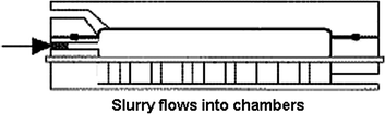
The equipment consists of a series of horizontal chambers one on top of the other on a continuous belt. In this way, the filter area per floor area is multiplied. The chambers are fixed in space and do not move during operation. The belt consists of a high resistance moving filter cloth mounted over driving rods, which move the filter belt during the discharge operation. In the upper part of the chambers are flexible rubber diaphragms that compress the cake during the expression cycle. The filtration cycle has the following stages:
-
1.
Cake formation
The slurry is pumped into all the filter chambers simultaneously. The solids begin to form as the filtrate displaces more slurry enters the chamber. As the solids build up, the pumping pressure increases. The filtrate is forced through the cloth until the required solid thickness is achieved.
-
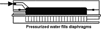
2.
Diaphragm Pressing I
High-pressure air or water automatically inflates the diaphragm located at the top of each chamber, reducing the chamber volume and squeezing the solids to remove additional filtrate. The tightly woven filter cloth produces clear filtrate. High pressure of over 5 bars maximizes efficiency. Pressing the diaphragm produces homogenous saturated solids of uniform thickness, which assists the air blowing step.
-
3.
Solid Washing
Pressure filters can wash dewatered solids in situ to maximize solute removal or to recover mother liquor with minimal dilution. The wash liquid distributes evenly on the homogenous solid since the filter plates are horizontal. The wash liquid flows through the solids, displacing the mother liquid with minimal mixing.

-
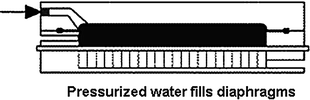
4.
Diaphragm Pressing II
The diaphragms are re-inflated, forcing the wash liquid uniformly through the solids. This produces a washing efficiency of over 95 %, with consistent saturated solids and minimum wash liquid consumption.
-
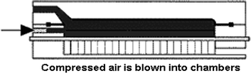
5.
Air Blowing
Compressed air blows through the solids for final dewatering. The moisture content reaches values around 8 % and is controlled by adjusting the pressure and duration of the blowing air.
-
6.
Solids Discharge and Cloth Washing
After the plate-pack opens, the dewatered solid is conveyed out of the chambers on the moving filter cloth (see Fig. 9.13).
Fig. 9.13 
Discharge of the filter cake


-
(c)
Candle filter
Filtration takes place in a pressure vessel. The filter consists of a series of porous tubes on the outside of which the cake forms. The filtrate flows inside the tubes and is collected at the bottom of the vessel. After completion of the cake formation cycle, the cake adhering to the filtration element is washed with a suitable medium. To ensure the driest possible product, the washed cake is dried for as long as necessary, with any of the following media: ambient air, hot air, nitrogen or steam. Figure 9.14 shows a candle filter.

Candle pressure filter
9.2.3 Hyperbaric Filter
Vacuum filters have 0.8 atmospheres as limiting pressure drop under the most favorable conditions, that is, at sea level. Using them in high mountains, where mines are usually found, the pressure drops drastically.
In the late 1980s Professor Dr. Werner Stahl and co-workers introduced vacuum filters, such as disk and drum filters, in a pressure vessel, in this way, increasing the available pressure drop. They can easily add four or more bars to a natural vacuum filter. This equipment is called a hyperbaric filter (see Fig. 9.15).

Hyperbaric filter showing the pressure chamber with a disc filter
As in all pressure filters, the discharge is a problem in this new filter. Humidity, which in vacuum filters does not fall to 15 %, reaches 8 % in hyperbaric filters.
9.3 Filtration Theory
Depending on the material to be filtered, and the magnitude of the pressure drop, the filter cakes can remain rigid or are compressed. Copper concentrates, and in general other metal concentrates, are incompressible if flocculants are not used during the thickening process. On the contrary, flocculants are always used with flotation tailings, so their filter cakes are compressible. When filtering these tailings, what is not that common, vacuum filter are used and therefore the pressure drop is small and the material can be considered incompressible under these conditions.
The conclusion is that in the majority of mineral processing plants filter cakes are nearly incompressible and the theory of flow through rigid porous beds is valid as the basis to develop a filtration system. If in some instances this is not the case, compression must be introduced in the theory.
-
Filtration with incompressible cakes
Consider a filtration process under the following restrictions:
-
1.
The properties of the suspension, the cake and the filtrate are constant.
-
2.
The cake formed is incompressible.
-
3.
The filtration surface is plane.
-
4.
The percolation velocity of the filtrate across the filter cake and the filter medium is slow.
Restriction (1) permits eliminating the densities from the material balances. From restriction (2), the filter cake is assumed to be rigid and the solid component of the particulate system is immobile. In cases of curved surfaces, for example in drum filters, restriction (3) requires that the diameter of the drum is much greater than the cake thickness and restriction (4) permits using Darcy’s law as a constitutive equation for the percolation velocity.
Filtration as a batch or a continuous process works in cycles that begin with the entry of pulp into the filter and ends with the discharge of the filter cake. A continuous filter is capable of making several thousand cycles before changing filter media or mechanical maintenance is necessary. In each cycle we can distinguish two fundamental stages: (a) the cake formation stage, which includes pumping the suspension into the filter chambers and compression of the suspension on the filter medium by means of pressured air, a rubber diaphragm or a piston, and (b) cake dewatering by blowing or suctioning air through the filter cake. In special cases, other stages are added, for example, if the filter cake is compressible a (c) expression stage is used to compress the cake to reduce its porosity and eliminate some of the water saturating the cake. If the solid material is to be free of contaminants, a (d) washing stage is used, followed by another dewatering stage.
9.3.1 Cake Formation
Consider the following field variables [see Eqs. (6.39) and (6.40)]: cake porosity \( \varepsilon (z,t) \), percolation velocity \( q(z,t) \) and excess pore pressure \( p_{e} (z,t) \). These variables constitute a simple filtration process if the following field equations are satisfied:
where \( \varepsilon_{0} \) is the constant porosity of the filter cake and \( q_{0} \;{\text{and}}\;k(\varepsilon_{0} ) \) are the percolation velocity and the cake permeability, both constant.
Consider Fig. 9.16 representing a filtration process with a plane rigid filter cake. Call \( p_{0} = p_{e} ({- \ell_{m}}), p_{m} = p_{em} ({\ell_{m}}) \) and, \( p_{\ell } (t) = p_{e} (\ell (t)) \), then the pressure drop \( \Updelta p_{1} = p_{\ell } - p_{m} > 0 \) and \( \Updelta p_{2} = p_{m} - p_{0} > 0. \)

Filtration with plane incompressible cake
The boundary conditions are:
The term simple refers to the fact that these equations represent the simplest case of a filtration process.
In vacuum filtration, the filter element is partially submerged in the suspension, which is fed with a pump. The suspension is kept homogeneous by agitation. In this case, the pressure drop is constant and depends on the available vacuum and local atmospheric pressure.
Pressure filters are fed with centrifugal pumps. At the beginning of the feeding process, the resistance of the cake and filter medium is low and the volume flow rate is high and relatively constant. As the cake resistance increases, the pressure drop also increases, while the volume flow rate decreases depending on the pump characteristic curve. Figure 9.17 shows the characteristic curves of a centrifugal pump and the curve of the system (see Chap. 11).

Characteristic curves of a centrifugal pump
Once the filter chambers are full of suspension, the feed is stopped and a constant pressure is applied by a rubber membrane. This step of the cake formation stage is called expression.
These considerations lead to the study of the filtration process in the special case of constant pressure drop.
-
(a)
Cake formation with constant pressure drop
Consider the case of a constant pressure drop across the filter cake and the filter medium:
Each pressure drop is a positive constant, therefore integration of Eq. (9.2) for a given instant t leads to:
where \( k_{m} {\text{ and }}\ell_{m} \) and \( k\left( {\varepsilon_{0} } \right){\text{ and }}\ell (t) \) are the permeability and thickness of the filter medium and of the filter cake, and \( q_{0} \) is the percolation velocity, that is, the volume flow rate of filtrate per unit filter area and \( \varepsilon_{0} \) is the porosity of the filter cake. Adding Eqs. (9.6) and (9.7) yields:
We define the filter medium resistance \( R_{m} = {{\ell_{m} } \mathord{\left/ {\vphantom {{\ell_{m} } {k_{m} }}} \right. \kern-0pt} {k_{m} }} \), so that (9.8) becomes:
The volume flow rate of filtrate \( Q_{f} \) can be expressed in terms of the percolation velocity \( q_{0} \), and in terms of the volume of filtrate \( V_{f} (t) \).
where S is the filtration area. \( Q_{f} \) has a simple relationship with the cake thickness \( \ell \); see Eq. (9.14). Substituting (9.10) in the previous equation gives:
-
Cake mass and thickness, filtrate volume and cake formation time
We want to obtain a practical cake formation equation involving the mass of solid \( m_{s} (t) \), the volume of filtrate obtained \( V_{f} (t) \) and the thickness of the filter cake \( \ell (t) \), all as functions of time t. The volume fraction of solids \( \varphi_{0} \) is written as:
The liquid volume is equal to the filtrate volume produced, plus the liquid retained in the saturated filter cake, then:
The solid mass is the volume of the solid in the filter cake times its density:
Substituting Eq. (9.13) with Eq. (9.12) and calculating \( \ell (t) \) or \( m\left( {\varepsilon_{0} ,t} \right) \) we get:
Expression (9.14) gives the relationship between the thickness of the filter cake and the mass of material filtered, with the volume of filtrate at any given time t. Substitution with Eq. (9.11) yields:
The only variable in this expression is the filtrate volume \( V_{f} (t) \), therefore integrating the time interval 0 to t gives:
-
Filtrate volume:
Solving the quadratic Eq. (9.16) yields the volume of filtrate over time:
-
Cake thickness
Substitution of \( V_{f} (t) \) from (9.14) with (9.16) gives the algebraic equation in terms of the thickness \( \ell (t) \) of the cake:
-
Cake mass:
Substituting Eq. (9.13) with (9.19) yields the cake mass formed at time t:
-
Cake formation time:
Inverting Eq. (9.20) the time to form a cake is:
All these expressions become simpler if the filter medium specific resistance \( R_{m} = \ell_{m} /k_{m} \) is neglected.
Filtrate volume:
Cake mass:
Cake thickness:
Cake formation time:
It is important to take note that the expressions for filtrate volume, cake mass and cake thickness are proportional to the square root of the product of the pressure drop and time.
Equations developed in the previous section are valid for cake formation in a steady state, but also for a dynamic process where the amount of solid deposited per time unit is small compared to the solid already forming the cake. This occurs throughout the main part of the cake formation stage, except at the beginning of the process. For example, during the feeding of a pressure filter, the flow is variable, but the process becomes steady when the compression starts. It is obvious that all the equations developed are valid for the washing stage of the filter cake.
Figure 9.18 shows the experimental curve of cake formation in the laboratory. The circles represent experimental points, while the curve was drawn with Eq. (9.17). For about 25 % of the filtration time, the filtration volume \( V_{f} (t) \) produced is proportional to the time t. From that time on, \( V_{f} (t) \) is proportional to \( t^{1/2} \).

Modeling of the cake formation step during pressure filtration
In effect, Darcy’s law is valid at any instant t, therefore:
For the first instance, the cake thickness \( \ell \) can be ignored, giving:
and the filtrate volume is a linear function for short times.
These considerations are important when filtration parameters are to be obtained in the laboratory.
-
(b)
Cake formation with constant volume
Filtration with constant volume occurs when the pulp is fed with a positive displacement pump. In this case, the volume flow rate is constant. Equation (9.8) is still valid, but now q is a constant and \( \Updelta p \) is variable:
where Q is the volume flow rate of filtrate. The thickness of the cake and the mass of solid in the cake is then:
Values for \( \Updelta p(t) \) should be obtained from the pump curve.
Problem 9.1 (Wakeman and Tarleton 1999a)
A filtration experiment is performed with a 45 cm2 area pressure filter at 70 kPa. The ratio of moist to dry cake is 1.34. The densities of the solid, filtrate and feed pulp are respectively: \( \rho_{s} = 2{\text{,}}640\;{\text{kg/m}}^{ 3} \), \( \rho_{f} = 1{\text{,}}000\;{\text{kg/m}}^{ 3} \) and \( \rho_{0} = 1{\text{,}}320\;{\text{kg}}/{\text{m}}^{ 3} \). The viscosity of the filtrate is \( \mu = 0.01\;{\text{poises}} \). The filtrate production in time is given in Table 9.1. Determine the time necessary to obtain a filter cake with a thickness of 4.5 cm.
Volume fraction of the suspension is \( \varphi_{0} = \frac{{\rho_{0} - \rho_{f} }}{{\rho_{s} - \rho_{f} }} = \frac{1{\text{,}}320\; -\; 1{\text{,}}000}{2{\text{,}}640\; - \;1{\text{,}}000} = 0.195 \)
Cake porosity:
but:
then:
There is a direct relationship between the mass in the cake, the suspension concentration, cake porosity and filtrate volume. From (9.14), we have:
From the table we can obtain the correlation between time versus the volume of filtrate (see Fig. 9.19).
Substituting \( V_{F} (t) \) in the equation for \( t\left( {V_{F} } \right) \) results in:

Filtrate volume in time, from the previous table
9.3.2 Cake Dehumidification
During the filtration process, the cake formation stage removes the main part of the water from the suspension. At the end of this stage, the suspension covering the filter cake disappears and the filter cake looks dry but its pores are saturated with water. Saturation s is the fraction of pore volume in a porous medium filled by water. The saturation varies between zero and one, \( 0 \le s\, \le\, 1 \). If \( s = 1 \), the cake pores are full of water and if \( s = 0 \), the cake is dry. The only way to eliminate water from a saturated filter cake is by expression and/or by dehumidification.
For compressible cakes, it is possible to eliminate some water by expression, that is, by applying pressure and squeezing the filter cake like a sponge. In this case, the mechanism of expression is the reduction of the pore size by compression.
In dehumidification, the water is displaced from the filter cake by air. During vacuum filtration, air is suctioned through the filter cake, while in pressure filtration the air is blown into the filter cake. During dehumidification, air and water flow simultaneously through the filter cake. In general, the solid particles attract water, wetting the solid skeleton. The air, on the contrary, displaces the water from the pores, but leaves a thin film adjacent to the solid surfaces held by capillary forces. These phenomena make the flow of water different in a water saturated and unsaturated porous medium.
To calculate the water and airflow through an unsaturated filter cake, the theory of two-phase flow through a porous medium is used (see Chap. 3). Darcy’s equation can be used in this case but here the permeabilities of the liquid and air are not functions of the cake porosity only, but are also a function of saturation, \( k_{i} (\varepsilon_{0} ,s),i = \ell ,a \), called effective permeabilities, where \( \ell \;{\text{and}}\;a \) refers to liquid and air respectively:
Relative permeabilities of the liquid \( k_{r\ell } (\varepsilon_{0} ,s) \) and air \( k_{ra} (\varepsilon_{0} ,s) \) are defined as the quotient between the effective permeabilities \( k_{\ell ,a} [(\varepsilon_{0} ,s)] \) and the permeabilities \( k_{\ell ,a} [(\varepsilon_{0} )] \) for the flow \( q_{l,a} \) under the same pressure gradient \( \partial p_{e} /\partial z \):
With these definitions of relative permeability, Darcy’s equation for the water and airflow in a filter cake are:
The relative permeabilities must be determined experimentally. Figure 9.20 shows the relative permeabilities of a wetting fluid (water) and a non-wetting fluid (air) in a filter cake.

Experimental relative permeability curves for the flow of water and air through a copper concentrate filter cake
When air is blown through the filter cake, it displaces the water from the pores and water and air leaving simultaneously. When the cake saturation reaches the residual saturation \( {\text{s}}_{\infty } \), only air will flow out. The rest of the water is retained in the cake by capillary forces.
Functional forms for the relative permeabilities must be postulated to introduce them in Eqs. (9.32) and (9.33)
where s and \( s_{\infty } \) are the instantaneous and the residual saturations, and i refers to the type of fluid.
-
Blowing time
Taking into consideration that \( q_{f} (t) = \partial V_{f} (t)/\partial t \), for the blowing stage Eq. (9.11) is written in the form:
The thickness of the cake is constant and equal to \( \ell = {{m_{s} } \mathord{\left/ {\vphantom {{m_{s} } {S\left( {1 - \varepsilon_{0} } \right)}}} \right. \kern-0pt} {S\left( {1 - \varepsilon_{0} } \right)}} \) and the water in the cake at time t is \( S\ell \varepsilon_{0} s(t) \), where \( s(t) \) diminishes with time. The filtrate volume is \( V_{f} (t) = S\ell \varepsilon_{0} \left( {1 - s(t)} \right) \), so that: \( dV_{f} /dt = - S\ell \varepsilon_{0} ds/dt \). Introducing these relationships in Eq. (9.35) yields an equation in terms of the saturation:
Integrating with respect to s:
Integrating, the blowing time to reach a saturation s is obtained:
The integral in (9.36) can be calculated once the function \( f(s) \) is known.
-
Airflow
Since in pressure filtration the pressure gradient is much greater than the saturation gradient, the latter can be neglected (see Sect. 6.5.4) and the air flow necessary to reach a given saturation can be obtained by directly integrating Eq. (9.33):
The air flow rate is \( Q_{a} = Sq_{a} \), therefore:
In these equations, \( R_{m} \;{\text{and}}\;S \) are equipment parameters, \( \rho_{s} ,k(\varepsilon_{0} )\;{\text{and}}\;\varepsilon_{0} \) are characteristic parameters of the porous medium, \( \rho_{\ell } \;{\text{and}}\;\mu_{\ell } \) are properties of the fluid and \( \Updelta p,\ell \;{\text{and}}\;s({\text{or}}\;t) \) are operational parameters and variables.
Humidity is the ratio of water mass to total mass expressed as percentage. Equation (9.38) gives the relationship between saturation and humidity:
9.3.3 Cake Washing
The same equations and methods used for cake formation and blowing can be used for cake washing, with a restriction on the concentration of the element that is to be eliminated.
9.4 Filtration Parameters and Their Measurements
Figure 9.4 shows the several variables and parameters that influence the filtration process. Inlet variables are feed pulp flow and concentration. Outlet variables are filter capacity, mass of solid filtered per time unit and the thickness and humidity of the filter cake. Design variables are filtration area and pressure drop in the equipment. Control variables are applied pressure, times for cake formation, washing, expression and blowing, temperature, pH, additives and pulp agitation. Perturbations are the type of material, particle size and size distribution, impurities in the feed material. Parameters are porosity, permeability and compressibility of the cake, relative permeabilities for air and water and residual saturation.
In the previous section, we developed relationships between these variables and parameters. To complete the necessary information to design and simulate a filtration process, it is necessary to determine the dependence of the parameters on the properties of the solid and the liquid.
9.4.1 Filtration Parameter Measurements
Several companies that provide equipment have laboratory instruments to measure filtration parameters that are based on similar principles but differ in the amount of sample they can take and the quality of their instrumentation. Here we will describe filtratest, an instrument designed by Bokela GmbH.
The core of filtratest is a stainless steel pressure vessel that supports pressures up to 10 bars (\( 150\;\psi \)) and therefore can simulate a vacuum and most pressure filtration processes. The instrument has a filtration area of 19.63 cm2 and a water jacket that permits operation at controlled temperatures. A set of rotameters of different sizes measures the airflow rate. A digital manometer controls air pressure. A beaker sitting on a digital balance receives and weighs the filtrate. The portability of the instrument is fundamental to take measurements at plant sites. The Fig. (9.21) shows the filtratest.

filtratest instrument
Software especially designed for this instrument registers the exact time and filtrate produced during cake formation, expression and blowing cycles. From these data, functional forms are postulated for the filtration rate and time, from which the permeabilities of the cake and the specific resistance of the filter medium are calculated. The relative permeabilities for the water and air are also calculated.
-
(a)
Cake porosity
The cake porosity is a function of the size distribution of the particles forming the porous bed. A bed formed of particles of only one size will have the same porosity irrespective of the size of the particles. The case of sphere packing illustrates this. Table 9.2 (Wakeman and Tarleton 1999b) shows the porosity for different types of sphere packing.
We can see that a three-fold value of the porosity of spheres is possible (0.26–0.78) for different types of packing. The nominal value used for porosity in filter cakes is \( \varepsilon_{0} = 0.4 \), a bit lower than the average in Table 9.2.
In the case of filter cakes, it is more useful to determine the porosity experimentally. There are three ways to do that: by drying and weighing the cake, by measuring the depth of the saturated cake, and by a water balance at the end of the bed formation time. When the cake is saturated, the water has disappeared from the suspension and the difference between the total water in the suspension and the water in the filtrate gives the volume of water saturating the cake, which is equal to the volume of pores in the cake.
Problem 9.2
A sample of copper concentrates was taken from a Larox pressure filter with a cylinder of 5 cm in diameter. The thickness of the sample was 35 mm. The weight of the sample after drying was 147 g and the density of the solid 3.87 g/cm3.
The cake porosity then was:
Problem 9.3
In a laboratory test 138.7 g of copper concentrate, with a density of 4,300 kg/m3, was filtered from a suspension of 72.2 % solid by weight. The cake formation time was \( t_{1} = 42.7\;{\text{s}} \) and, during that time, 20.6 cm3 of filtrate was recovered. Calculate the saturated cake porosity.
For compressible filter cakes, constitutive equations, such as Eqs. (9.39) and (9.40) describe their porosity (Tiller et al. 1985):
Problem 9.4
Laboratory tests were performed with 80 g of a copper flotation tailing in the Filtratest having 19.63 cm2 of filter area, giving a cake with a porosity \( \varepsilon = 0.493 \) at a pressure drop of 0.75 bars. Tests at different pressure drops yielded the result shown in Table 9.3. Determine the constitutive equation for the compressibility of the cake as a function of porosity.
The correlation between the pressure p s and thickness height is, see Fig. 9.22

Cake thickness heights versus pressure drop for a copper flotation tailing
The cake thickness for a pressure of 0.75 bars is
Calculating the cake volume \( V_{c} \) and the solid volume \( V_{s} \) from the filter area and the cake thickness, for a pressure of \( p = 0.75 \), we obtain:
Finally, the values of the cake porosity for the various pressures \( p_{s} \) are calculated from:
Figure 9.23 shows a plot of the solid volume fraction versus the applied pressure.

Solid volume fraction (1 − ε) versus pressure drop for a copper flotation tailing
From Fig. 9.23 the following constitutive equations can be obtained by non-linear fitting:
The constitutive equation for the solid pressure is:
Problem 9.5
A flotation tailing is filtered in a vacuum band filter at 0.75 bars, obtaining a cake with \( \varepsilon_{0} = 0.493 \) in porosity. An experimental test to determine the compressibility of the cake gave the following constitutive equation:
What would the porosity be if the same material were filtered in a hyperbaric filter with 3 bars of overpressure and in a Larox PF filter at 6 bars.
For the different filters, we have:
-
(b)
Filter medium resistance and cake permeability
The filter medium is an important component in the filtration process. It is a medium with pores of different sizes and geometry, the structure of which can cause variations in the way in which the particles are deposited and in the distributions of the filtrate flow. A filter cloth must not only retain the solid particles and produce a clean filtrate, but must also resist the stresses imposed by the equipment. Therefore in addition to the specific resistance to filtration, we must consider the mechanical resistance as another parameter.
-
Experimental determination
To determine the specific resistance of a filter medium \( R_{m} \) and the permeability of the filter cake \( k(\varepsilon ) \) Eq. (9.17) is written in the form:
where \( R_{m} = {{\ell_{m} } \mathord{\left/ {\vphantom {{\ell_{m} } {k_{m} }}} \right. \kern-0pt} {k_{m} }} \), and \( \ell_{m} \) and \( k_{m} \) are the thickness and permeability of the filter medium, information that is usually not known.
Write Eq. (9.43) in the form:
From the plot of \( {t \mathord{\left/ {\vphantom {t {V_{f} }}} \right. \kern-0pt} {V_{f} }} \) versus \( V_{f} \), the value of \( R_{m} {\text{ and }}k(\varepsilon_{0} ) \) can be obtained from the intercept “a” on the ordinate and from the slope “b” of the straight line (see Fig. 9.27):
Problem 9.6 (Massarani 1978)
Calculate the filtration area necessary to treat 10,000 \( 1/{\text{h}} \) of a 5 % by weight calcium carbonate suspension. The solid density is 2,500 kg/m3. The filter operates at 20 °C and \( 40\;\psi \) of pressure. Laboratory experiments with a filter with 500 cm2 area and \( 40\;\psi \) pressure give a cake 3.2 cm in thickness. The weight percentage of solids of the cake is 60.2 % and the viscosity is \( \mu = 1\;{\text{cp}} \). Figure 9.24 shows a plot of \( t/V_{f} \) versus \( V_{f} .\)

Plot of t/Vf versus Vf to calculate filtration parameters
-
Parameters:
From Fig. 9.24 the ordinate intercept \( a = 0.0071 \) and the slope is \( b = 1 \; \times \; 10^{ - 6} \) and from Eq. (9.44), the intercept and slope are given by:
From (9.45):
From Eq. (9.11) the filtration area is:
Problem 9. 7
Calculate the permeability and resistance of the filter medium of a material filtered in the laboratory at 70 kPa through a filter area of 45 cm2. The ratio of the wet and dry cake weight was 1.34. The solid, filtrate and feed pulp densities is \( \rho_{s} = 2{\text{,}}640\;{\text{kg}}/{\text{m}}^{ 3} \), \( \rho_{f} = 1{\text{,}}000\;{\text{kg/m}}^{ 3} \) and pulp density \( \rho = 1{\text{,}}320\;{\text{kg}}/{\text{m}}^{ 3} \). The filtrate viscosity is \( \mu_{f} = 0.01\;{\text{poises}} \). Table 9.4 shows the filtrate production over time:
Calculate the permeability and filter medium resistance.
Volume fraction in the feed:
The ratio of wet to dry cake is the inverse of the solid fraction of the cake, therefore:
Volume fraction of solids in the cake:
Cake porosity \( \varepsilon = 1 - \varphi_{ck} = 1 - 0.527 = 0.473 \)
Plotting \( t/V_{f} \) versus \( V_{f} \), we obtain the Fig. 9.25.

Determination of the cake permeability and filter medium resistance
From the figure a = 0.88946 and b = 0.00246, so that:
Specific resistance of the cake is:
Problem 9.8
Calculate the specific resistance of the filter medium and the cake permeability for a copper concentrate filtered in a Larox PF filter. A laboratory test was performed in the filtratest having a filtration area of 19.63 cm2. A sample of 156.78 g of solid was filtered at 2 bars for 39.76 s, time at which the cake was formed. The volume of filtrate formed at any time was registered and is shown Fig. 9.26.

Filtrate volume versus time for the laboratory experiment in a FILTRATEST. The line gives the polynomial correlation
The following data are known: (Tables 9.5, 9.6, 9.7)
Plotting t/Vf versus Vf in Fig. 9.28, we get the correlation:
From Fig. 9.28 the values of a and b are \( a = 3.0855\;{\text{s/cm}}^{3} \) and \( b = 0.029\;{\text{s/cm}}^{6} \), then:
- Pulp concentration:
-
78 % solid
- Feed volume fraction:
-
\( \varphi_{0} = \frac{78}{3.87 \; \times \; (100\, -\, 78) \,+ \,78} = 0.478 \)
- Cake porosity:
-
\( \varepsilon = 1 - \frac{156.78/3.78}{19.63 \; \times \; 3.6} = 0.43 \\ \)
\( \begin{aligned} k\left({\varepsilon_{0}} \right) =\; & \frac{1}{b} \; \times \; \frac{{\mu_{f}}}{{2S^{2} \Updelta p}}\frac{{\varphi_{0}}}{{1 - \varphi_{0} - \varepsilon}} \\ = \;& \frac{1}{0.029}\frac{0.012}{{2 \; \times \; (19.63)^{2} \; \times \; 2 \; \times \; 10^{6}}}\frac{0.48}{1 - 0.478 - 0.43} = 5.74 \; \times \; 10^{-9}\; {\text{cm}}^2 \end{aligned}\\ \)
-
Effect of the particle size
The Kozeny–Carman equation for the permeability of porous media was given in Sect. 6.3, Eqs. (6.29)–(6.33):
These equations show that the permeability of a filter cake depends on the characteristics of the particles through two particle parameters, the average particle size and the particle shape, both squared, and on the porosity through the function \( {{\varepsilon^{3}} \mathord{\left/{\vphantom {{\varepsilon^{3}} {(1 - \varepsilon)^{2}}}} \right. \kern-0pt} {(1 - \varepsilon)^{2}}} \). This last function, as we have already seen, depends on size distribution, the packing factor and particularly the applied pressure.
Problem 9.9
For the data of problem 9.8, use the Kozeny–Carman equation to predict the permeability of a filter cake formed at 6 bars of applied pressure.
At 4 bars of cake formation pressure, the porosity was \( \varepsilon = 0.43 \). Since the copper concentrate is practically incompressible, we can assume that at 4 and 6 bars the porosity will be the same. Assume a sphericity of \( \psi = 0.5 \) for the concentrate. The particle size distribution is given in Table 9.8.
The surface volume average is \( \bar{x}_{12} = \frac{1}{{1.85 \; \times \; 10^{- 2}}} = 54.18\;\upmu {\text{m}} \) and the equivalent volume diameter \( d_{e} = 0.69 \; \times \; \bar{x}_{12} = 0.69 \; \times \; 54.18 = 37.39\;\upmu {\text{m}} \) (Concha et al. 1973). After Coulson and Richardson (1968), \( \beta = 5 \), therefore:
-
(c)
Residual saturation and capillary curve
The entry pressure and the residual saturation are two important parameters to determine the operating conditions of an industrial filter. Entry pressure is the minimum pressure at which a saturated filter cake begins dewatering. It is the lower boundary for the blowing pressure. Residual saturation is the value at which the saturation does not decrease with increased pressure.
Problem 9.9
Calculate the entry pressure and the residual saturation for a copper concentrate, with a density \( \rho_{s} = 3.87\;{{\text{g}} \mathord{\left/{\vphantom {{\text{g}} {{\text{cm}}^{ 3}}}} \right. \kern-0pt} \;{{\text{cm}}^{3}}} \), having the data of Table 9.9, plotted in Fig. 9.28 showing the values \( p_{b} = 0.20 ,\quad s_{\infty} = 0.50. \)
The figure shows that it is unnecessary to blow air at pressures over 2.5 bars, and that the minimum saturation possible is s = 0.50. Since the porosity is \( \varepsilon = 0.43 \), the minimum humidity of the final cake is:
-
Correlation for the residual saturation
According to Wakeman, see Eqs. (6.74) and (6.75) of this book, the residual saturation can be calculated in terms of the capillary number with the following equations:
where \( N_{cap} \) is the capillary number, \( \varepsilon_{av} {\text{ and }}\ell \) are the average cake porosity and the thickness, \( \bar{x}_{12} \) is the surface-volume average particle size, \( \Updelta p \) is the pressure drop across the cake and \( \gamma \) is the liquid surface tension.
Problem 9.10
Determine the residual saturation for the filter cake of the previous problem. The experimental information is:
The value obtained with Wakeman’s correlation is about 35 % of the experimental value of \( s_{\infty} = 0.50 \).
-
(d)
Relative permeability
We defined the relative permeability of the water and that of the air in a porous medium at time t, as the ratio of the respective water and air permeability at time t and the permeability of the saturated cake. As we know, this last parameter is a property solely of the porous medium.
To calculate the permeabilities of the water and the air during the blowing filtration stage, the flow of water and air as a function of time must be known (Table 9.10).
Problem 9.11
Determine the relative permeabilities of water and air for a copper concentrate filtration process. Experiments were made with the filtratest on a copper concentrate pulp with 73 % solid by weight. Experimental conditions were: \( \Updelta p = 6\;{\text{bars}} \) for the cake formation stage, filtration area \( S = 6.55\;{\text{cm}}^2 \), temperature \( T = 20\;^\circ {\text{C}} \), filtrate viscosity \( \mu = 1\;{\text{mPa-s}} \), air viscosity \( 0.0187\;{\text{mPa-s}} \), concentrate density \( \rho_{s} = 4.50\;{{\text{g}} \mathord{\left/{\vphantom {{\text{g}} {{\text{cm}}^{ 3}}}} \right. \kern-0pt} {{\text{cm}}^3}} \). At the end of the filtration cycle, the humid cake weighed 46.57 g and after drying, the weight was 43.27 g. The cake formation stage took 37 s and liberated 5.79 g of filtrate. The expression stage eliminated 4.56 g of filtrate during 38 s at \( \Updelta p = 7.5\,{\text{bars}} \). Finally, during 121 s, air blown at \( \Updelta p = 6\,{\text{bars}} \) liberated 1.99 g of additional filtrate. Table 9.11 shows data for the several filtration stages. The rate of filtrate production is given in the first two columns of Table 9.12, for the cake formation stage, and the first three columns of Table 9.13 for the blowing stage.
-
Cake permeability
To calculate the cake permeability, we model the filtrate volume flow from Table 9.12.
Figure 9.29 shows a plot of the filtrate volume versus time for the cake formation stage.
From the figure, the following correlation are obtained:
Using this correlation, a graph \( t/V_{f} {\text{versus}}V_{f} \) yields Fig. 9.30.
From the correlation \( t/V_{f} = 4.7322 + 0.2848V_{f} \), the following parameters a and b are:
With these values, the permeability and the filter medium resistance are:
Relative permeability
The first four columns of Table 9.13 show data for the blowing stage. The plot of the filtrate volume versus time for the blowing stage gives: (see Figs. 9.31, 9.32, 9.33, 9.34):

Classical t/V f versus V f curve for the determination of the permeability and the filter medium resistance

Capillary curve: pressure drop versus saturation

Filtrate volume versus time for the cake formation stage

Plot of t/V f versus V f for a copper tailings

Plot of V f versus time for the blowing cycle

Filtrate flowrate during the blowing stage

Air flowrate in the blowing stage

Effective filtrate and air permeabilities
The effective and relative permeabilities of the filtrate and of the air are given by:
The saturation is given by:
The residual saturation is \( s_{\infty} = 0.535 \), so that the reduced saturation becomes:
The relative permeabilities can now be correlated with the reduced saturation in the form (see Fig. 9.35):

Relative permeability versus reduced saturation
9.5 Continuous Modeling
9.5.1 Vacuum Filters
Vacuum filtration is an important process in the mining industry and for the first half of the 20th century it was the only filtration process in practice.
In this type of filtration, pulp feeds a tank in which a filter is submerged. The side of the filter in contact with the feed is at atmospheric pressure while the other side connects to a vacuum pump that provides a pressure drop across the filter. The difference in pressure drives the filtrate across the filter medium leaving the solid adhering in the form of a cake. The maximum theoretical pressure available for this type of filter is one atmosphere, but the pressure drop in the piping system and, especially, the height of the location with respect to sea level drastically diminishes this value, often reaching 0.6–0.8 bars. Thus vacuum filtration operates at low and constant pressure drop and therefore the filter cake produced is incompressible.
Rotary drum, disc, band and pan filters operate under vacuum. The selection of the appropriate filter for a given duty depends principally on the material to be filtered. Pulps with large solid particles, such as potassium chloride or potassium sulphide crystals, are difficult to maintain in suspension and therefore band filters are best, while disc or drum filters are appropriate for pulps of fine material.
One of the main costs of using filter cloth is the air consumption with power demands on the order of 2–15 kW/m2 of filter area (Henriksson 2000). An alternative to filter cloth is ceramic plates made of alumina. These filters are homogeneous and have small pores on the order of 2 mμ, which produce capillary suction according to the Young–Laplace equation (see Sect. 6.5.1 in this book). This action permits fluid flow through the filter medium with minimum help from a vacuum, requiring only about 0.05 kW/m2 of filter area (Henriksson 2000). The principal problem with ceramic filters is blockage of the pores with small solid particles that must be removed with acid leaching.
-
Rotary Filter Model
Consider a rotary vacuum filter, for example a disc filter, rotating at N rpm with cake formation and dehumidification stages. The time t R, in minutes, for each revolution is \( t_{R} = 1/N \). If the fraction of this time used during the cake formation is I, then, the time for the cake formation stage \( t_{0} \) and the time for dehumidification \( t_{3} \) are:
-
cake formation stage:
$$ t_{0} = I \; \times \; t_{R} = \frac{I}{N} ,\quad \min/{\text{rev}} $$(9.47) -
dehumidification stage
$$ t_{3} = \left({1 - I} \right) \; \times \; t_{R} = \frac{1 - I}{N} ,\quad \min/{\text{rev}} $$(9.48)
Assume that the filter is submerged in the suspension forming an arc with an angle of \( \theta \), as is shown in Fig. 9.36. The fraction of time I in cake formation must be equal to the fraction of filter area submerged in the suspension, that is \( I = \theta/360 \), then, Eqs. (9.47) and (9.48) become:

Rotary vacuum filter
-
(a)
Cake formation
The relationship between the production of filtrate and the cake formation time is given by Eq. (9.16), therefore:
Substituting (9.49) in this equation yields the volume of filtrate per revolution:
Rearranging:
Dividing by \( S^{2}/N^{2} \) gives:
-
Filtrate flow rate
The term \( V_{f} (N)N/S = q_{0} \) is the filtrate flow rate produced per unit area during N revolutions. Substituting the previous equation yields an equation for the production of filtrate during the cake formation time
The solution to this equation is:
-
Mass flow rate
The mass flow rate relates to the filtrate flow rate by Eq. (9.14), that is
Substituting Eq. (9.51) yields:
Neglecting the filter media resistance, Eqs. (9.54) and (9.52) become:
Equations (9.51)–(9.54) permit the calculation of a rotary vacuum filter capacity. In these equations \( \varphi_{0} \) is the suspension volume fraction, \( \varepsilon_{0} \;{\text{and}}\;k\left({\varepsilon_{0}} \right) \) are the filter cake porosity and permeability during the cake formation stage, \( \rho_{s} \) is the solid particle density, \( \mu \) is the filtrate viscosity, \( \Updelta p \) is the total pressure drop across the filter, N is the filter velocity in rpm and \( \theta \) is the angle subtended by the part of the filter submerge in the suspension.
It is useful to separate the variables in Eqs. (9.53) and (9.54) that are properties of the suspension, the cake and the filtrate from operating variables:
-
Cake thickness
The cake thickness is related to its mass by Eq. (9.13):
Replacing Eq. (9.57) with Eqs. (9.56) or (9.52), depending whether or not the filter medium resistance is omitted, yields:
-
(b)
Cake dehumidification
The cake dehumidification takes place by vacuum suction of the filtrate in the interior of the equipment from the atmosphere at the surface of the filter cake. The suction time \( t_{3} \) is given by Eqs. (9.36) and (9.49), then:
This equation relates the rotation speed to the final saturation. The air flow during the dehumidification stage is given by Eq. (9.37):
In these equations \( k_{r\ell} (s) \) and \( k_{ra} (s) \) are the relative permeabilities of the liquid and air respectively.
Problem 9.12
A rotary drum filter with 3 m2 of area operates at a speed of 0.5 rpm, an internal pressure of 30 kN/m2 and 30 % of its surface area submerged. The atmospheric pressure is 1.013 × 10⁵ N/m2. Calculate the filter capacity and the final humidity of the cake. The cake is incompressible and the filter cloth resistance is equivalent to the resistance of a 1 mm filter cake. The following data are known:
Submerged angle | \( \theta = 120^\circ \) |
Surface area | \( S = 3{\text{m}}^{2} \) |
Rotational speed | \( N = 0.5\;{\text{rpm}} \) |
Atmospheric pressure | 1.013 × 10⁵ N/m2 |
Internal pressure | 30 kN/m2 |
Suspension concentration | \( N = 0.5\;{\text{rpm}} \) |
Cake porosity | \( \varepsilon_{0} = 0.40 \) |
Cake permeability | \( k\left({\varepsilon_{0}} \right) = 5 \; \times \; 10^{- 13} {\text{m}}^{ 2} \) |
Cake thickness | \( \ell = 2.3\;{\text{cm}} \) |
Solid density | \( \rho_{s} = 2{\text{,}}000\;{{\text{kg}} \mathord{\left/{\vphantom {{\text{kg}} {{\text{m}}^{ 3}}}} \right. \kern-0pt} {{\text{m}}^{ 3}}} \) |
Filtrate density | \( \rho_{\ell} = 1{\text{,}}000\;{{\text{kg}} \mathord{\left/{\vphantom {{\text{kg}} {{\text{m}}^{ 3}}}} \right. \kern-0pt} {{\text{m}}^{ 3}}} \) |
Filtrate viscosity | \( \mu_{a} = 1 \; \times \; 10^{- 3} \;{\text{Pa - s}} \) |
Air viscosity | \( \mu_{a} = 1.85 \; \times \; 10^{- 5} \;{\text{Pa - s}} \) |
Liquid relative permeability; | \( k_{r\ell} = \exp \left({4.466\left({s_{r}^{2} - 1} \right)} \right) \) |
Air relative permeability | \( k_{ra} = \frac{{0.5521 \; \times \; \left({1 - s_{r}} \right)}}{{1 - 0.9155 \; \times \; s_{r} - 0.07643 \; \times \; s_{r}^{2}}} \) |
Results:
Pressure drop | \( \Updelta p = 1.013 \; \times \; 10^{5} - 0.3 \; \times \; 10^{5} = 0.713 \; \times \; 10^{5} \;{\text{N}}/{\text{m}}^{ 2} \) |
Suspension concentration | \( \varphi_{0} = 20 \; \times \; 1{\text{,}}000/(2{\text{,}}000 \; \times \; (100 - 20) + 20) = 0.111 \) |
Filter medium resistance | \( R_{m} = \frac{{1 \; \times \; 10^{- 3}}}{{k\left({\varepsilon_{0}} \right)}} = \frac{{1 \; \times \; 10^{- 3}}}{{5 \; \times \; 10^{- 13}}} = 2 \; \times \; 10^{9} \;{\text{m}}^{- 1} \) |
Rotation time | \( t_{R} = \frac{1}{N} = \frac{60}{0.5} = 120\;{\text{s}} \) |
Filtration time:
Cake formation time | \( t_{1} = \frac{\theta}{360}t_{R} = \frac{120}{360} \; \times \; 120 = 40\;{\text{s}} \) |
Dehumidification time | \( t_{3} = \left({1 - \frac{\theta}{360}} \right) \; \times \; t_{R} = \left({1 - \frac{120}{360}} \right) \; \times \; 120 = 80\;{\text{s}} \) |
Capacity:
Filter capacity given by (9.52)
Cake thickness:
From Eq. (9.57): \( \ell = \frac{{m_{s}}}{{\rho_{s} \left({1 \;- \;\varepsilon_{0}} \right)SN}} = \frac{0.792}{{2{\text{,}}000 \; \times \; \left({1 \;- \;0.4} \right) \; \times \; 3 \; \times \; {{0.5} \mathord{\left/{\vphantom {{0.5} {60 \; \times \; 100}}} \right. \kern-0pt} {60 \; \times \; 100}}}} = 2.64\;{\text{cm}} \)
Filtrate flow: \( Q_{f} = \frac{{m_{s}}}{{\rho_{s}}}\frac{{1\; - \; \varphi_{0} \;- \;\varepsilon_{0}}}{{\varphi_{0}}}\frac{1}{{1 \;- \;\varepsilon_{0}}} = 0.0025\;{\text{m}}^{ 3}/{\text{s}} \)
Cake humidity:
Equation (9.34) relates the filtrate flow to the relative permeability:
The relative permeability is then:
If the constitutive equation of the relative permeability of the filtrate is given by:
Then, the reduced saturation is:
The final saturation is:
and the final humidity is:
Air flow
The relative air permeability is given by:
The airflow through the filter cake is given by:
9.5.2 Pressure Filters
As we said in Sect. 9.2.2, pressure filters work in a semi-continuous manner, that is, with filter cycles.
Pulp is fed to the filtration chambers from a manifold with as many rubber hoses as there are filtration chambers. The chambers are closed spaces between the filtration cloth and the rubber diaphragm. As soon as all the chambers are closed, the pulp is pumped and distributed evenly across the horizontal surface of the filter cloth in all the chambers. When the chambers are full, air is pumped to the other side of the diaphragms. Although filtration starts when the pulp begins to enter the chambers, the cake formation continues until no further filtrates comes out of the cake. If the material is compressible, the diaphragm pressure reduces the cake porosity in an expression stage. Once cake formation and expression are finished, air is blown through the cake to displace the water retained in the pores. Finally, automatic mechanisms open the set of filtration plates to discharge the cake. The table below shows a typical filtration cycle for a Larox pressure filter (Droguett 2000).
Stage | Function | Time (s) |
|---|---|---|
1 | Closing the plates | 50 |
2 | Filling the filtration chambers | 85 |
3 | Washing the feeding tube | 13 |
4 | Washing the feeding hoses | 50 |
5 | Pressing and expression | 80 |
6 | Compressed air release | 5 |
7 | Opening and closing the outlet tubes | 30 |
8 | Cake blowing | 100 |
9 | Pressure drainage | 10 |
10 | Opening the feeding valve | 1 |
11 | Cake discharge | 18 |
12 | Filter cloth washing | 72 |
14 | Total cycle | 514 |
The table shows that time is divided into effective filtration time, cake formation t 1 , cake pressing t 2 and cake blowing t 3 and time that is not used for filtration, which is called dead time t 4. The filtration time is 265 s and the dead time is 249 s. Optimizing a filtration system should shorten filtration time and especially dead time.
Problem 9.13
With the data from problem 9.11, calculate the capacity, in tpd, of a horizontal pressure filter with 144 m2 in filter area, to produce a copper concentrate cake, \( \rho_{s} = 4{\text{,}}500\;{\text{kg}}/{\text{m}}^{ 3} \), with 8.5 % humidity. The feeding and cake formation takes t 1 = 85 s at Δp = 6 bars producing a cake of 3.0 cm. An expression stage at 7.5 bars takes t 2 = 75 s and is followed by a blowing stage at 6 bars.
From problem 9.11 we have the following data and parameters:
Cake formation stage:
Expression stage:
Reduction of porosity from \( \varepsilon_{0} = 0.520 \) to \( \varepsilon = 0.362 \)
Blowing stage:
Reduced permeability correlations:
Since the solid volume is the same before and after pressing, we can write:
Blowing time
To obtain the desired humidity of 8.5 %, the saturation must be:
From expression (9.35) and from the relative permeability of the liquid, with parameters \( a = - 4.466256\;{\text{y}}\quad b = 4.4661532 \), we obtain the blowing time to get a saturation of 0.4344:
Airflow:
The airflow is calculated from (9.36):
Air consumption:
Filter capacity:
The time for one cycle is:
Therefore, for each cycle of 506 s, a cake is formed in 85 s.
Mass per cycle:
References
Concha, F. (1990). Suspension Rheology. Universidad de Concepción, (in Spanish).
Droguett, M. H. (2000). Optimization of the filtration system of the Coloso Plant, Minera Escondida. Engineering Thesis. University of Concepción, (in Spanish).
Henriksson, B. (2000). Focus on separation in the mining industry. Filtration + Separation, 37(7), 26–29.
Holdich, R. (1996). Simulation of compressible cake filtration. Filtration + Separation, 31, 825–829.
Massarani, G. (1978). Problems in Particulates Systems. COPPE/UFRJ, 21. (in Portuguese).
Massarani, G. (1997). Fluodynamics of Particulate Systems. UFRJ (in Portuguese).
Tiller, F. M. (1953). The role of porosity in filtration. Numerical method for constant rate and constant pressure filtration based on Kozeny′s law. Chemical Engineering Progress, 49(9), 467–479.
Tiller, F. M. (1958). The role of porosity in filtration, part III, variable-pressure-variable rate filtration. AIChE Journal, 6(4), 170–174.
Tiller, F. M., & Cooper, H. R. (1958). The role of porosity in filtration. Part IV. Constant pressure filtration. AIChE Journal, 6(4), 595–601.
Tiller, F. M., & Cooper, H. R. (1962). The role of porosity in filtration. Part V. Porosity variations in filter cakes. AIChE Journal, 8(4), 445–449.
Tiller, F. M., & Shirato, M. (1964). The role of porosity in filtration. Part VI. New definition of filter resistance. AIChE Journal, 10(1), 61–67.
Tiller, F. M., & Lu, W. (1972). The role of porosity in filtration. Part VIII, cake non-uniformity in compression-permeability cells. AIChE Journal, 18(3), 569–572.
Tiller, F. M., & Yeh, C. S. (1987). The role of porosity in filtration. Part XI, filtration followed by expression. AIChE Journal, 33(8), 1241–1256.
Tiller, F. M., Hsyung, N. B., & Cong, D. Z. (1985). The role of porosity in filtration. Part XII, filtration with sedimentation. AIChE Journal, 41(5), 1153–1164.
Wakeman, R. J., & Tarleton, E. S. (1999a). Filtration: Equipment selection, modeling and process simulation (pp. 81–82). Oxford: Elsevier Sci.
Wakeman, R. J., & Tarleton, E. S. (1999b). Filtration: Equipment selection, modeling and process simulation. Oxford: Elsevier Sci. 23.
Author information
Authors and Affiliations
Corresponding author
Rights and permissions
Copyright information
© 2014 Springer International Publishing Switzerland
About this chapter
Cite this chapter
Concha A., F. (2014). Filtration. In: Solid-Liquid Separation in the Mining Industry. Fluid Mechanics and Its Applications, vol 105. Springer, Cham. https://doi.org/10.1007/978-3-319-02484-4_9
Download citation
DOI: https://doi.org/10.1007/978-3-319-02484-4_9
Published:
Publisher Name: Springer, Cham
Print ISBN: 978-3-319-02483-7
Online ISBN: 978-3-319-02484-4
eBook Packages: EngineeringEngineering (R0)