
Abstract
Phacodynamics is the study of the physical principles that influence intraocular fluidics during phacoemulsification surgery. The two principles which comprise this discipline are phacofluidics and ultrasound energy. Phacofluidics describes the factors influencing the flow of fluid into, within, and out of the eye during phacoemulsification surgery. Phacoemulsification is the use of ultrasound energy transmitted by a phaco probe to fragment lens matter.
Access provided by Autonomous University of Puebla. Download chapter PDF
Keywords
- Phacofluidics
- Phacoemulsification
- Aspiration flow rate
- Peristaltic pump
- Venturi pump
- Dual-linear
- Cumulative dissipated energy
Introduction
-
Phacodynamics is the study of the physical principles that influence intraocular fluidics during phacoemulsification surgery.
-
When challenges are anticipated or encountered, ‘first principles’ can be used to adapt surgical technique and machine settings to achieve optimal safety and ease of surgery.
-
The two principles which comprise this discipline are phacofluidics and ultrasound energy.
-
This chapter will explain these principles at a functional level and how they practically apply to machine settings during the stages of phacoemulsification.
Phacofluidics
-
Phacofluidics describes the factors influencing the flow of fluid into, within, and out of the eye during phacoemulsification surgery.
-
It is best understood as a three-part circuit comprising fluid inflow from an infusion system, flow within the anterior chamber (AC), and outflow from an aspiration system (Fig. 1).
Fig. 1 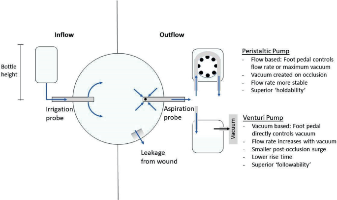
The fluidics circuit
-
Irrigation and aspiration may be delivered either through a single probe with a coaxial handpiece, or separately with a bimanual configuration.
-
Infusion is normally provided through two ports either side of an irrigation sleeve, which should be orientated in the plane of the iris to avoid trauma to the endothelium from the fluid current.
-
This circuit is a primary determinant of the intraocular pressure (IOP), and consequently anterior chamber stability.
-
The surgeon should aim to maintain a formed and stable anterior chamber, without excessively high IOP.

The fluidics circuit
-
Flow occurs through the fluidics circuit when both irrigation and aspiration are active.
-
Flow occurs along pressure gradients. The flow rate through this circuit is ultimately determined by the relative difference between irrigation and aspiration pressures.
-
The aspiration flow rate (AFR) is usually expressed in cm3/min. Pressure is expressed in mmHg.
-
It is useful to consider the resultant IOP as the balance between AFR and fluid replacement via the infusion side of the system. So long as the infusion keeps up with the AFR, a steady state occurs in the AC and the flow rate is determined by the aspiration setting.
Dealing with a shallow anterior chamber
If the anterior chamber is found to shallow during the operation, it follows that either the irrigation pressure is insufficient, or aspiration pressure is excessive, to adequately keep the anterior chamber formed. Whilst it may be tempting to ameliorate this by simply increasing inflow, or decreasing the AFR, the following considerations should be made:
-
Infusion: Check that the infusion line is not obstructed, and bottle is not empty.
-
Aspiration: Check the integrity of the main wound and paracenteses, which are usually responsible for the majority of fluid outflow during surgery. A second instrument placed through a paracentesis that is too large will cause on-going leakage during surgery and cause eddy currents and AC instability. This significantly increases the risk of posterior capsular rupture and iris prolapse. Adjust your handling of the instruments to minimise leakage, and if possible, remove your second instrument.
-
Be aware that a shallow anterior chamber can be caused by positive vitreous pressure, which is the anterior displacement of the lens-iris diaphragm as a result of raised pressure within the posterior segment. This can be recognised when the AC is shallow despite a high IOP, which can be quickly confirmed by palpating the globe to judge its firmness. Important causes of positive vitreous pressure include hydration of the vitreous by aqueous misdirection into the posterior segment, a tight lid speculum, a large body habitus, and a suprachoroidal haemorrhage.
Fluid inflow
-
Fluid inflow is provided by an infusion system, which delivers fluid into the eye by way of either ‘passive’ or ‘active’ pressure from the fluid source.
Passive systems
Passive systems rely on the gravitational potential energy created by holding the bottle a certain height above that of the eye.
-
Raising the ‘bottle height’ relative to the patient will increase the infusion pressure and therefore potential flow rate (subject to aspiration) but also increase the IOP.
-
The infusion pressure is determined by bottle height less the flow resistance in the delivery tubing. For every 15 cms of bottle height above the eye, there is a pressure increase of 11 mmHg.
-
The bottle height automatically changes to pre-set levels when switching the mode of phaco (for example sculpting to segment removal). It can also be changed using the interface settings.
-
It should be noted that adjusting the height of the patient’s head or operating table, for example to make room for the surgeon’s legs when operating temporally, will also change effective bottle height.
-
These systems are conceptually easy to understand and employ, but maximal flow rate is limited and changes to the settings are not implemented immediately.
Passive infusion without aspiration
When only irrigation is active, assuming no loss through incisions or ports, the IOP will quickly reach an equilibrium with the infusion pressure, while the flow rate will fall close to zero.
-
In this circumstance there is a linear relationship between infusion pressure and IOP.
-
Sustained raised IOP will create hydrostatic pressure within the eye. This may stress the zonular fibrils, hydrate the cornea which compromises visibility, and hydrate the vitreous which increases positive vitreous pressure, the latter of which may eventually shallow the anterior chamber. Furthermore, it can be painful for the patient as well as potentially worsening glaucomatous optic neuropathy if maintained for long periods.
-
Therefore, avoid leaving irrigation active without aspiration for significant periods of time.
Active systems
Active systems generate pressure either from compressed air into a rigid bottle, or mechanical compression of a flexible infusion bag.
-
This allows for higher potential flow rates, which may contribute to increased anterior chamber stability. However, this also causes a corresponding increase in IOP, particularly when aspiration is not active.
-
They also can achieve near instantaneous adjustments of pressure, and some machines can be programmed to automatically maintain a target IOP (and therefore stable AC) as chosen by the surgeon by dynamically adjusting the infusion pressure.
Fluid outflow
-
Aspiration systems create flow which draws material out of the anterior chamber.
-
As the purpose of aspiration is not only to draw out fluid, but also lens matter or viscoelastic, the flow rate may not correspond to the vacuum level. For example, if the port is occluded with a lens fragment, the flow rate will fall to zero, whereas vacuum will rise. This may cause fluctuations in IOP as well as impacting the infusion flow rate, therefore affecting anterior chamber stability.
-
There are two kinds of aspiration systems: peristaltic pumps and venturi pumps.
Peristaltic pumps
Peristaltic pumps utilise rollers to compress the outflow tubing as the pump rotates. This creates a ‘milking’ motion which draws fluid through the tubing.
-
The tubing used is flexible, in order to be ‘compliant’ to the compression. The consequence of this is that when the aspiration is activated, there is a time taken to building the pre-set maximum vacuum to be reached once occlusion of the phaco tip has occurred. This is because the tubing itself constricts during the adjustment. This is called the rise time, and is influenced by the speed of the pump; The faster the pump, the quicker the rise time.
-
When the occlusion is subsequently cleared, the flow rate momentarily surges as the sudden reformation of the tubing creates volume and therefore additional momentary vacuum beyond what the machine is set to. This is called the ‘post-occlusion surge’ and may cause sudden spikes in the flow rate, and thus affect anterior chamber stability.
Venturi pumps
-
Venturi pumps operate by creating a vacuum using low pressure air within a rigid cassette with a fluid reservoir, which the fluid is drawn into.
-
The tubing used is rigid, therefore rise time is generally lower.
-
The surgeon can only control the vacuum, rather than the AFR directly, and therefore these are also liable to post-occlusion surges.
Aspiration settings
The aspiration settings between these two systems differ significantly.
-
Peristaltic systems, by virtue of having physical rollers drawing the fluid, are considered ‘flow based’ and AFR remains relatively stable until occlusion. Only when occlusion occurs does vacuum significantly build, but they can achieve high vacuum at lower AFR than venturi systems. This can potentially allow for safer surgery, but also means these systems are not able to draw lens fragments towards the probe as easily. They can be configured to control either the AFR or maximal vacuum using the foot pedal at any one time, the other being adjustable on the machine interface. This potentially could be advantageous in the stop and chop technique, where high maximal vacuum should be combined with low AFR; note that the rise time will be slow in these circumstances.
-
Venturi systems only allow control of vacuum, which directly affects the flow rate. They produce higher AFR at lower vacuum than peristaltic systems, but are also potentially less controllable. This creates faster flow within the anterior chamber and hence helps to draw in and hold onto lens fragments during segment removal, although can also inadvertently do the same for the iris or capsule. As such, venturi systems are classically considered to allow faster and more efficient surgery, albeit with greater potential for complications. Note that elevation of infusion bottle height will increase the AFR as well as IOP.
Phacoemulsification
-
Phacoemulsification is the use of ultrasound energy transmitted by a phaco probe to fragment lens matter.
-
This ultrasound energy is generated by running an electrical current through piezoelectric crystals, situated within the phaco probe, which then vibrate at a fixed high frequency.
-
Ultrasound energy not absorbed by lens matter will dissipate as thermal energy within the surrounding media. If used excessively, this has the potential to cause corneal wound, iris or endothelial trauma. It is therefore important to minimise the cumulative dissipated energy (CDE).
-
The irrigation sleeve plays a role in keeping the phaco tip cool.
-
The surgeon’s aim should be to efficiently fragment and aspirate lens matter whilst minimising thermal trauma to surrounding structures.
-
Phaco can be delivered in ‘continuous’, ‘pulsed’ or ‘burst’ mode. In all, the phaco power is increased linearly with further foot depression. Pulsed mode, as the name suggests, delivers power in pulses when phaco is activated, whose duration as a proportion of the total time phaco is active is referred to as the duty cycle. In burst mode the maximum set phaco power is delivered in succession, the frequency of which is increased by depressing the pedal further down. This allows for more efficient use of power and produces less repulsive force (as described below) and allows time between pulses to dissipate heat from the phaco tip.
-
The frequency of pulses is expressed as pulses per second (PPS).
Phaco needle movement
-
The oscillations of the phaco probe conventionally occur in a longitudinal axis, whose distance of travel is referred to as the stroke length. Increasing the phaco power (normally expressed as a percentage of the maximum available) increases the stroke length and thus force delivered.
-
In addition to emulsifying the lens, these movements may also cause repulsion of the fragments, pushing them away from the probe. If this overcomes the occlusion caused by the vacuum, the lens fragment may be rapidly thrust back and forth close to the tip of the phaco probe, which could be described as ‘chattering’. This is highly inefficient and also compromises anterior chamber instability.
-
Increasing phaco power facilitates emulsification but may make achieving occlusion more difficult and increases the amount of thermal energy produced.
-
Newer phaco probe designs have incorporated torsional, for example the OZil handpiece (Alcon Inc.), and transverse ultrasound, for example the Ellips handpiece (AMO Inc.). As the movement is predominantly ‘side-to-side’, there is significantly reduced tip travel, and hence lower repulsive force. These are more efficient because the tip “cuts” in both directions of the oscillation and requires less vacuum for occlusion, and reduces the risk of thermal trauma.
Phaco needle design
The phaco tip significantly impacts the ease of certain intra-operative manoeuvres, and it is therefore important to become acquainted with the advantages and drawbacks of the various designs. It is also important to consider the required incision size for any given tip design.
-
Needle size: Phaco probes usually come in 0.9 mm and 1.1 mm bore needles. Larger needles allow for an exponentially greater flow rate with the same level of vacuum, which allows for faster surgery, although at the risk of being potentially less controlled.
-
Angle of bevel: Phaco tips which are significantly angled allow for easier sculpting and cracking of the lens, whilst blunter tips allow easier achievement of occlusion.
-
Needle shape: Various designs are available which are suited to different operating techniques (Fig. 2). For example, the Kelman flared 45º phaco tip (Alcon Inc.), suited for torsional and longitudinal phaco, has an enlarged port to reduce post-occlusion surge, but can be subject to clogging. The angled end may make sculpting easier, but also pose a greater risk to the capsule and corneal endothelium.
Fig. 2 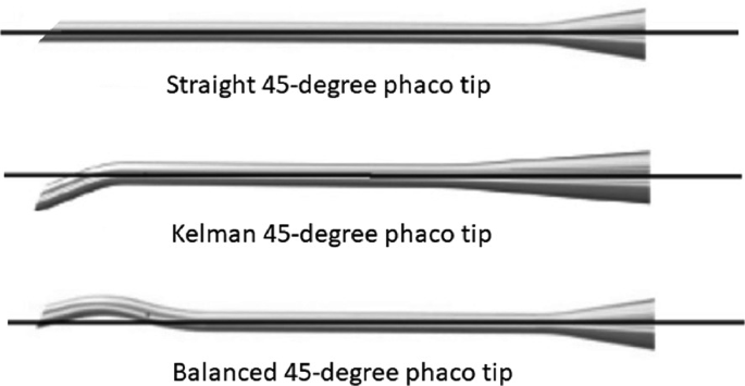
Examples of phaco tip designs

Foot pedal control
The conventional ‘linear’ arrangement of foot pedal controls is outlined in Fig. 3. Note that the foot pedals can be configured in certain machines, such as Bausch and Lomb Stellaris, to control both aspiration and phaco power in independent linear modes by assigning either ‘pitch’ (depression of the pedal) and ‘yaw’ (transverse movement of the pedal) movements to one of each (‘dual-linear’ setting). Foot pedal controls usually also incorporate an auto-reflux control, by which flow can be reversed to release aspirated material back into the AC.

Illustration of linear foot pedal control
-
The irrigation (inflow) is activated by depression of the foot pedal to position 1 (see Fig. 3). The irrigation pressure is at a pre-set level which can only be adjusted on the machine panel.
-
The aspiration is activated in position 2 and increases linearly up to its maximum pre-set limit by further depression of foot pedal. Be aware that if AFR exceeds the ability of the irrigation pressure to replace fluid loss, the AC will collapse. On the other hand, if aspiration ceases (in cases such as occluded outflow tubing or failed vacuum) during active phaco, then the AC will become cloudy with lens materials.
-
The third position of the foot pedal actives phaco power. As with aspiration, this is usually set to a linear increase in power along with depression up to the pre-set maximum.
Fluidic settings
-
Cataract surgeons should use their own machine settings for any specific cataract system. This establishes a ‘baseline’ of familiar phacodynamics, whose predictability suits the surgeon’s technique.
-
When deciding standard machine settings, the main variables to consider are the phaco technique being used, features of the handpiece/needle, and the wound size.
-
The following table summarises the rationale for each stage and should serve as a guide for selecting your own standard phaco settings (Table 1).
Table 1 Suggested machine settings -
Note that with advances in phaco technology and automated fluidic management by phaco systems, surgery can be carried out with increasingly lower infusion and aspiration settings, and with reduced post-occlusion surge and other causes of anterior chamber instability.
Bibliography
Benjamin L. Fluidics and rheology in phaco surgery: what matters and what is the hype? Eye (Lond). 2018;32(2):204–9. https://doi.org/10.1038/eye.2017.299.
Fishkind W, Wallace B, Henderson B, Colvard M, Devgan U, Serafano D, Chu R, Davis E, Gills J. Cataract and refractive surgery today. 2008. Online at https://crstoday.com/wp-content/themes/crst/assets/downloads/CRST0908_05.pdf.
Kent C. Phaco: know your fluidics options. Rev Ophthalmol. 2017. Online at https://www.reviewofophthalmology.com/article/phaco-know-your-fluidics-options.
Mckinney S. Phaco update: getting the right setting. Rev Ophthalmol. 2021. Online at https://www.reviewofophthalmology.com/article/phaco-update-getting-the-right-setting.
Seibel B. Phacodynamics, 4th ed. Slack Inc.; 2004.
Sullivan P, Benjamin L, Little B. Phacoemulsification surgery. Eyelearning ltd. 2019. Online at https://books.apple.com/.
Acknowledgements
We would like to thank Larry Benjamin for his kind review and great suggestions.
Author information
Authors and Affiliations
Corresponding author
Editor information
Editors and Affiliations
Rights and permissions
Copyright information
© 2023 The Author(s), under exclusive license to Springer Nature Switzerland AG
About this chapter

Cite this chapter
Toufeeq, S., Shalchi, Z. (2023). Phacodynamics. In: Shajari, M., Priglinger, S., Kohnen, T., Kreutzer, T.C., Mayer, W.J. (eds) Cataract and Lens Surgery. Springer, Cham. https://doi.org/10.1007/978-3-031-05394-8_44
Download citation
DOI: https://doi.org/10.1007/978-3-031-05394-8_44
Published:
Publisher Name: Springer, Cham
Print ISBN: 978-3-031-05393-1
Online ISBN: 978-3-031-05394-8
eBook Packages: MedicineMedicine (R0)