
Abstract
Wire arc spraying (WAS) is one of the oldest of thermal spray processes. Compared to alternate surface modification technologies, WAS is most competitive because of its high deposition rates up to 25 kg/h, favorable economics and potential use for a wide range of applications mostly for corrosion protection of infrastructure such as bridges and metallic constructions, as well as in the marine and automotive industry. The technology is based on the concept of sticking an arc between two wires, or a single wire and a non-consumable electrode. As the tip of the wire(s) melts, the formed molten metal is atomized by a high-velocity gas stream, forming a spray of molten metal droplets that is projected toward the substrate on which it is deposited forming the coating. The atomizing gas being essentially at room temperature, the substrate is not subjected to heated during the spray process. The main limitation of the technology is that it works best for the spraying of ductile metallic wires, such as aluminum, zinc, or steels. The development of the “cord–wire” approach in which a wire is formed through the use of a ductile metallic foil as envelop filled with a ceramic or composite fine powder allowed the expansion of the technology to new industrial-scale wear resistance applications involving the spraying of carbide-based cermets such as Cr3C2 with Fe and FeC, WC/W2C + Fe, WC/TiC + Fe, Cr, Ni. The technology can be combined with epoxy or silicon polymer coating for the sealing open porosity in the coating provided that the service temperature is below (< 200 °C). In this chapter, the basic concepts behind the technology are discussed highlighting the fundamental phenomena involved. This is followed by a review of industrial torch designs with emphasis on their relative advantages, limitation, and arc-droplet dynamics and their impact on coating quality. Process technology is reviewed next with examples of some of the leading WAS applications.
Access provided by Autonomous University of Puebla. Download chapter PDF
Keywords
- Wire arc spraying
- Single wire
- Twin wire
- Corrosion protection
- Wear-resistant coatings
- Rebuilding worn parts
- High-temperature erosion and oxidation protection
1 Introduction
Wire arc spraying (WAS) is the oldest of thermal spray processes, with its first patent issued in the USA in 1915 by Schoop (1915). It was only in the 1960s that the real potential of the technology was recognized, and its applications greatly expanded. This was mainly due to significant improvements in our understanding of the fundamentals governing the process technology through systematic studies involving high-time resolution diagnostics (Steffens 1966). By the late 1990s and the beginning of the twenty-first century, several significant improvements in the equipment design and processes automation were achieved (Steffens et al. 1990; Marantz and Marantz 1990). Compared to alternate surface modification technologies , WAS is one of the most competitive technologies because of its high deposition rates up to 25 kg/h, favorable economics, and potential use for a wide range of applications mostly for corrosion protection of infrastructure such as bridges and metallic constructions in general as well as in the marine and automotive industry. The main limitation of the technology is that it works best with metallic ductile wires , such as aluminum, zinc, or steels. The development of the “cord–wire” approach in which a wire is formed through the use of a ductile metallic foil as envelop filled with a ceramic or composite fine powder allowed the expansion of the technology to new industrial-scale wear resistance applications involving the spraying of carbide-based cermets such as Cr3C2 with Fe and FeC, WC/W2C + Fe, WC/TiC + Fe, Cr, Ni for wear resistance application. The technology can be combined with epoxy or silicon polymer coating for the sealing open porosity in the coating provided that the service temperature is below < 200 °C. In this chapter, the basic concepts behind the technology are discussed highlighting the fundamental phenomena involved. This is followed by a review of industrial torch designs with emphasis on their relative advantages, limitation, and arc droplet dynamics and their impact on coating quality. Process technology is reviewed next with examples of some of the most extensively used WAS applications.
2 Basic Concepts
2.1 General Remarks
Wire arc spray (WAS) is a plasma spray coating process based on the concept of melting the material to be sprayed in wire form using an electric arc struck between their tips of two wires, or a wire and a non-consumable electrode, and atomizing the formed molten metal by a high-velocity gas stream which projects the droplets toward the substrate. As with conventional thermal spraying, the molten droplets form splats that rapidly solidify on impact with the substrate surface building up the coating in successive layers (Davis 2004; Tucker 2013). As schematically represented in Fig. 11.1, the process can be maintained in a continuous mode by electrically connecting the two wires to a DC power supply and continuously feeding the wires in a closely controlled speed to compensate for the melting of their respective tips such as to maintain a constant gap between them and consequently a constant arc voltage. A high-velocity gas flow injected between the two wires toward the arc removes constantly formed molten material from the wire tips, breaks down the larger droplets into smaller ones in a secondary atomization process, and propels them toward the substrate. The shearing of the liquid metal layer from the wire tips by the high-velocity gas flow can be perceived in the high-speed photographs given in Fig. 11.2.

Principle of wire arc spraying

High-speed images of liquid metal droplet formation with 100 ns exposure time
Numerous wire and atomizing gas nozzle configurations have been used in the design of wire arc spraying torches. The setups schematically represented in Fig. 11.3. for the twin-wire arc spray (TWAS) torch can be characterized as follows: Fig 11.3a is the standard nozzle with a straight bore, Fig 11.3b is a converging–diverging nozzle allowing supersonic flow of the atomizing gas to extend farther into the atomizing region, Fig 11.3c is standard nozzle with secondary gas injection, and Fig 11.3d is the addition of a shroud to the nozzle with secondary gas injection. As will be discussed later in detail, the effects of each of these arrangements are mostly felt on the atomizing gas velocity, formed droplet size and velocity, droplet temperature, droplet trajectories, and coating characteristics .

Schematics of different wire and atomizing gas nozzle configurations used in the design of twin-wire arc spraying torches . (a) Standard straight bore nozzle. (b) Laval type nozzle. (c) Straight bore nozzle with secondary gas flow. (d) Straight bore nozzle with secondary gas flow and solid shield surrounding the spray jet (Wang et al. 1999)
Alternate torch designs also include the so-called single-wire arc spraying (SWAS) with a single consumable wire electrode and a non-consumable second electrode (Marantz and Marantz 1990; Marantz et al. 1991; Kowalsky et al. 1991, 1992; Steffens and Wewel 1991; Steffens and Nassenstein 1994; Carlson and Heberlein 2002). Such a design which has also been commonly referred to as the plasma transferred wire arc spraying (PT-WAS) has the advantages of potentially generating a narrower spray pattern, with a smaller and lighter-weight torch using significantly reduced atomization gas flow rates. All the materials normally used as wires for the twin-wire arc spray processes could be equally used with this process as well. Single-wire arc spraying torches are, however, still in its early stages of their development and less commonly used on an industrial scale compared to conventional twin-wire arc spraying devices.
Compared to plasma spraying , the heat transfer to wires is excellent, and the droplets are fully molten when they leave the wire tips. The atomizing gas plays a key role in droplets formation with the formed particles smaller than the wire diameters and their acceleration and impact velocity also strongly dependent on the atomizing gas and also on the design of different gas injection nozzles. The droplets are generally spherical in the size range from sub-micron (fume) up to 200 μm depending on spray conditions. Droplet sizes increase with the increase of the arc current, the atomizing gas flow, the wire size, and the decrease of the arc voltage. Atomizing gas flow rates are generally rather high up to 1.8 m3/min; air is mostly used for economic reasons at the expense of risking the potential oxidation of the material being sprayed either in-flight or after its deposition on the substrate. Considering that the atomizing gas is not heated, the heat flux to the substrate is limited to the sensible and latent heat of the molten droplets spray, which is significantly lower than that experienced in processes such as combustion DC or RF induction plasma spraying. Low melting point substrates can consequently be safely coated with this process without the need for additional cooling. On the other hand, preheating the substrate to improve the coating adhesion, when necessary, would require the use of an additional heat source. Droplet oxidation can be significantly reduced through the use of inert atomizing gas such as argon or nitrogen and reducing the spraying distance. Coatings with thicknesses over 1 mm are easily attainable. Typical operating ranges are 15–400 A, with open circuit voltage of 40 V. Scaled-up units operating with arc currents up to 1500 A are used with high throughput for the coating of large parts such as bridges. Typical material feed rates with standard WAS systems given in Table 11.1 (Davis 2004) are higher than comparable DC plasma spraying units.
To summarize, the principal advantages of the wire arc spray process are:
-
Use of wire as the feed material, which is more economical than the use of powder.
-
Efficient and complete wire melting resulting in high deposition efficiencies.
-
High energy efficiency since the major portion of the electrical energy supplied is used for melting the wire tips and all material arriving at the substrate was initially molten.
-
Minimal heat transferred to the torch, eliminating the need for water cooling and permitting smaller and simpler torch designs.
-
High gas flow rates and the relatively low power result in low gas enthalpies and, consequently, minimal substrate heating.
-
Small arcing gaps result in lower arc voltages,
-
Arc initiation through touching of the wires eliminating the need for high frequency starting unit.
2.2 Droplet Formation Mechanism
In this section, a discussion is presented regarding the basic mechanism involved in molten metal atomization and metal droplet formation. While the analysis is made for the conventional twin-wire arc spraying process, the basic concepts involved are equally valid for single-wire wire arc spraying torch design.
According to Lefebvre (1989), the atomization mechanisms, i.e., the way the molten metal layer is sheared from the wire tip and subsequently subjected to secondary atomization, are mainly governed by Raleigh breakup and membrane breakup mechanisms. While the velocity of the atomizing gas influences strongly the primary atomization, in many situations, the fluid dynamics of the torch has an even stronger influence on the secondary atomization downstream of the arc zone. The low-density, high viscosity, arc acts as a barrier for the cold gas cross flow, and a substantial portion of the atomizing gas flows around the arc column, forming a vortex street. Metal droplets are further atomized in this vortex sheet and can change direction, resulting in further dispersion of the spray pattern. A secondary nozzle close to the wire tip location strongly affects the gas flow, increases the gas velocity at the wire tips, and reduces the jet divergence.
An earlier study by Kawase et al. (1984a, b) in which the anode wire and cathode wire feed rates were varied independently contributed to the identification of:
-
Stable operating region when the anode wire feed rate is approximately the same as that of the cathode wire
-
Self-regulating operation with the cathode wire feed rate slightly higher than the anode wire feed rate
-
Unstable operation when either feed rates (and the current) are too low to melt the wires
Having approximately the same feed rates for the anode and cathode wire results in the highest droplet temperatures and optimal coating adhesion (Kawase and Kureishi 1985a, b), with higher voltages improving the adhesion. The differences between the arc–anode interface compared to that of the arc–cathode results in differences in the droplet formation at the anode and cathode wires (Steffens et al. 1990; Wang et al. 1999). This is illustrated in Fig. 11.4 showing a constricted arc attachment at the cathode wire, and a more diffuse attachment at the anode wire, leading to the formation of a large molten metal sheet from the anode wire with the arc attachment traveling toward the downstream end of this sheet (Hussary and Heberlein 2001).

High-speed images of arc attachment on wire tips showing a constricted attachment at the cathode (−) wire and a diffuse attachment at the anode wire (+) (Hussary and Heberlein 2001)
High-speed photographs cross-referenced to voltage values obtained through synchronization of an oscilloscope with the high-speed CCD camera are given in Fig. 11.5 (Hussary and Heberlein 2007). These show the forward movement of the anode arc attachment with the associated increase in voltage and formation of droplet and their detachment from the wire tip. Operating parameters were arc current = 300 A, voltage = 33 V, pressure = 69 kPa. A photograph of the entire jet of metal droplets given in Fig. 11.6 (Hussary and Heberlein 2001) shows periodic variations in particle fluxes. Typically, a burst of particles is emitted after a dip in the voltage, indicating a momentary peak in the arc current and melt rate. This is usually followed by a steady stream of particles for a good part of a millisecond, until the particle stream subsides, the voltage drops to a minimum followed by another burst of particles (Sheard et al. 1997). The voltage dip can reach a zero value, indicating a direct contact between the tip of the two wires. Such a situation results in an explosive emission of large metal droplets, which are broken up in the secondary atomization zone. Figure 11.7 shows Schlieren images of droplet dynamics in the arc. In particular, the LHS image reveals a secondary breakup of a large metal droplet (Hussary 1999). Clearly, this occurrence results in the broadening of the spray pattern and of the particle size distribution.

High-speed images of metal droplet formation synchronized with arc voltage trace, showing the forward movement of the anode arc attachment with the associated increase in voltage. Operating parameters: current = 300 A, voltage = 33 V, pressure = 69 kPa (Hussary and Heberlein 2007)

Photograph of a wire arc spray jet showing the periodic variation of droplet flux (Hussary and Heberlein 2001)

High-speed Schlieren images of the droplet jet from the wire arc spray torch, positioned at the left of the figure, showing the divergence of the droplet beam during a large droplet formation event and secondary atomization event with droplet breaking up into a range of smaller droplets (Hussary 1999)
The primary causes for such voltage fluctuations are:
-
Improper match of the voltage and wire feed rate settings, or too low open circuit voltage. Arc extinction may be responsible for a voltage spike before the dip to zero, caused by the arc blown toward the end of a liquid metal sheet followed by the detachment of the liquid metal.
-
Uncontrolled movement of the wire tips due to the “cast and kink” in the wires or due to wear of the wire guide and contact tips.
-
Differences in the melt rates of the anode and cathode wires.
The size distribution of the formed metal droplets depends on the atomization mechanisms, i.e., the way the liquid metal layer is sheared initially from the wire tips and on secondary atomization. Classifications of the various disintegration mechanisms in jets and liquid sheets have been the subject of numerous studies (Chigier 1981, Mansour and Chigier 1990, and Lin and Reitz 1998). These show that aerodynamic atomization of the liquid jets (liquid jet co-flowing with high-velocity gas stream) are governed by two important non-dimensional numbers, the Reynolds number , Re, and the Weber number , We, defined as:
where:
-
dℓ diameter of the liquid jet (m)
-
Lℓ characteristic dimension such as the liquid sheet thickness (m)
-
uℓ velocity of the liquid (m/s)
-
ur relative velocity of the liquid to gas stream (m/s)
-
ρℓ liquid density (kg/m3)
-
ρg gas density (kg/m3)
-
μℓ dynamic viscosity of the liquid (kg/m.s)
-
σℓ surface tension of the liquid (N/m) (kg/s2)
Liquid jet breakup is generally recognized to involve the following principal mechanisms:
-
Axisymmetric Rayleigh breakup (We < 15),
-
Non-axisymmetric Rayleigh breakup (15 < We < 25),
-
Membrane breakup (25 < We < 70)
-
Fiber-type breakup (100 < We < 500).
The first three types of primary atomization mechanisms are most frequently observed in wire arc spraying corresponding to relatively low Weber numbers (< 100) (Chigier 1981; Lefebvre 1989; Mansour and Chigier 1990). A schematic representation of the axisymmetric and non-axisymmetric Raleigh breakup mechanisms is presented in Fig. 11.8 (Hussary and Heberlein 2007). Primarily, the thermophysical properties of the liquid (molten metal) such as viscosity, surface tension and density, and the relative velocity between the atomizing gas and the liquid determine the predominant breakup mechanism. In the WAS process, the constant transient variation of the properties of the molten metal gives rise to corresponding variation in the breakup behavior. The axisymmetric Raleigh breakup of the anode liquid sheet is schematically illustrated in Fig. 11.8a, while Fig. 11.8b shows the non-axisymmetric Rayleigh breakup of the anode liquid metal sheet leading to droplet formation from extended liquid metal ligaments and the membrane-type breakup due to hole formation in a cathode liquid metal sheet .

Schematic illustration of (a) axisymmetric breakup of anode sheet and (b) non-axisymmetric breakup of the anode sheet and membrane-type breakup of the cathode sheet (Hussary and Heberlein 2007)
High-speed images of such breakups at the wire tips during spraying using carbon steel wires are shown in Fig. 11.9 (Hussary and Heberlein 2007). The non-axisymmetric breakup is the most frequently observed mechanism at the anode for almost all operating conditions, while the cathode frequently shows a membrane-type breakup together with the non-axisymmetric breakup, especially at higher voltages. The high-speed videos (18,000–40,500 frames/s) also show that increasing the wire feed rate/current setting will increase the wire melting rate. Increasing the voltage, on the other hand, will in general not result in larger gaps but rather in arcs that are strongly bowed in the direction of the flow or more likely to move toward the end of a liquid metal ligament. Consequently, an increase in droplet temperatures is to be expected with higher-voltage settings.

High-speed images of liquid metal atomization of the carbon steel wire tips showing (a) disintegration of the anode sheet in an axisymmetric Raleigh breakup, (b) a non-axisymmetric Raleigh breakup of a curved anode sheet, (c) anode sheet curvature due to large eddies, and (d) a membrane-type breakup of the cathode sheet with holes forming in the membrane (Hussary and Heberlein 2007)
It should also be noted that, while the atomizing gas velocity influences strongly the primary atomization, in many situations, the fluid dynamics of the torch has an even stronger influence on the secondary atomization downstream of the arcing zone. The low-density arc acts as a barrier for the cold gas cross flow, and a substantial portion of the atomizing gas flows around the arc, forming a vortex street behind the obstacle. Metal droplets are further atomized in this vortex street and can change direction, resulting in further dispersion of the spray pattern. A secondary nozzle close to the wire tip location will strongly affect the gas flow, increase the velocity at the wire tips, and reduce the jet divergence.
Droplet formation in the wire arc spray process is not, however, a closed issue. While higher velocity gas flows at the location of the wire tips will result in smaller droplet sizes, it is obvious that the entire fluid dynamics of torch and surroundings affect significantly this process. The role of secondary atomization is presently not fully understood. Furthermore, there appears to be some contradicting evidence reported in the open literature on the effect of the other operating parameters on droplet size distributions and the role of wire polarity. Relatively few studies have been performed on the electrical characteristics of the power supply and the rectifier’s responds to voltage fluctuations. The variations in the droplet’s formation are recognized to be linked to the instant voltage fluctuations which are linked in turn to:
-
Improper match of voltage and wire feed rate settings, too low open circuit voltage
-
Movement of the wire tips due to the cast and kink in the wires or wear of the contact tips
-
Differences in the melt rates of the anode and cathode wires
2.3 Particle Size Distribution
The effect of the atomizing gas velocity on particle size distributions (PSD) is demonstrated in Fig. 11.10 (Wang et al. 1999). It is to be noted that the pressure values given in this figure were measured at the control panel. These would correspond to almost double the gas pressure at the torch. The PSD values are given in number, and not in the more conventional volume or mass fractions, which would move them toward the smaller particle sizes. The results show that an increase of the torch pressure will result in a finer average droplet diameter and narrower PSD due to the increase of the atomizing gas velocity. The data given in Fig. 11.10 are for aluminum particles obtained by spraying aluminum wire into ice and determining the particle size distribution of the powder obtained using SEM and image analysis.

Aluminum particles size distributions obtained for different atomizing gas pressures (a) 309 kPa (45 psig), (b) 447 kPa (65 psig), and (c) 584 kPa (85 psig) (Wang et al. 1999)
An interesting observation was reported by Planche et al. (2003) who measured droplet size distributions at different distances from the torch axis for a TAFA 9000 torch used with converging cap nozzle, operating at 100, 150, and 200 A and air flow rates between 1567 and 2167 slm. The size distributions were different at different distances from the torch axis, ranging from relatively narrow and mono-modal on the axis to wider multimodal distribution with larger average particle diameters at off-axis locations.
In an attempt to explain the source of the bimodal nature of the PSD reported by different authors, and to determine the effect of nozzle design and operating parameters on the PSD for the droplets produced, Liao et al. (2005) carried out a systematic study using the three different nozzle configurations given in Fig. 11.11. These were adapted to a TAFA 9000 torch with nozzle (Fig. 11.11a) being a standard closed spray nozzle with a convergent orifice referred to as (C/CL nozzle). Figure 11.11b illustrates a second nozzle design which is of open configuration and incorporating an upstream convergent–divergent atomization nozzle without a cap (CD/OP nozzle). Figure 11.11c shows a modified closed nozzle with a converging–diverging orifice and secondary gas flow (Liao et al. 2005). To trace the source of a particle in the spray, i.e., whether it is resulting from the anode or cathode wires, wire materials with different magnetic properties were used for the anode and cathode, such as copper and steel. After spraying into water, the steel particles were separated from the copper ones using a magnetic field. Typical results presented in terms of volume fractions which are equivalent to the mass distribution of the powder are given in Fig. 11.12 (Liao et al. 2005). These were obtained using a stand torch with a C/CL nozzle, with the particles sprayed into water with a standoff distance of 300 mm, a torch operating at 30 V and 200 A. Copper and steel wires were used in these experiments with the copper wire being alternately as anode (Fig. 11.12a & b) or cathode (Fig. 11.12c & d). Two different atomizing air supply pressures, 0.28/0.28 MPa (Fig. 11.12a & c) and 0.46/0.49 MPa (Fig. 11.12b & d), were used for primary and secondary gas flows, respectively.

Schematic of different nozzle configurations considered: (a) C/CL, standard TAFA 9000 spray nozzle, closed nozzle and convergent orifice. (b) CD/OP Open nozzle with convergent–divergent Laval orifice. (c) CD/CL closed nozzle with convergent-divergent Laval-type secondary nozzle (Liao et al. (2005)

Particle size distribution of droplets generated using a standard C/CL TAFA 9000 nozzle, from an anode copper wire (a & b) and a cathode copper wire (c &d) with supply pressure of the atomization and secondary gases of 0.28/0.28 MPa (a & c) and 0.46/0.49 MPa (b &d) (Liao et al. 2005)
The following observations are made (Liao et al. 2005):
-
Both the anode and the cathode wire deliver droplets with binary size distributions, i.e., the binary size distributions observed in other experiments, are not necessarily due to the different droplet sizes from the anode and the cathode wires.
-
The size distribution becomes close to mono-modal at high supply pressure of the atomizing gas.
The average particle diameter obtained from the copper and steel wires used in different polarity combination and operating conditions are given in Fig. 11.13 (Liao et al. 2005). These are presented under the following set of conditions:
-
Group 1: regular atomizing gas nozzle with secondary nozzle, 0.28/0.28 MPa supply pressures, straight polarity
-
Group 2: regular atomizing gas nozzle with secondary nozzle, 0.28/0.28 MPa supply pressures, reversed polarity
-
Group 3: regular atomizing gas nozzle with secondary nozzle 0.46/0.49 MPa supply pressure, straight polarity
-
Group 4: regular atomizing gas nozzle with secondary nozzle, 0.46/0.49 MPa supply pressure, reverse polarity
-
Group 5: regular atomizing gas nozzle with a Laval-type secondary nozzle, 0.32/0.32 MPa supply pressure, reversed polarity
-
Group 6: Laval-type atomizing gas nozzle without secondary nozzle, 0.32/0.32 MPa supply pressures, reversed polarity
Fig. 11.13 
Average droplet/particle sizes for anode wires and cathode wires for different configurations and operating conditions (Liao et al. 2005)

The results show that, for copper, the average size of the droplets is not significantly different whether the wire is used as anode or as cathode. This is not the case for steel wires which show about 20% larger mean droplet diameter when the steel wire is used as anode compared to that when the wire is used as cathode. Moreover, considering the same polarity, the average size of the steel droplets is larger than that for the copper for droplets originating from the anode, while the reverse is observed for the droplets originating from the cathode. That implies that the wire material has a strong influence on the relative importance of the polarity.
A similar study on the of the effect of wire polarity on the PSD of copper and steel powders was reported by Pourmousa et al. (2005) using with a Sulzer Metco ValuArc 200 operated with a wire feed rate of 7 m/min, arc voltage of 32 V, and gas supply pressure of 0.208 MPa resulting in an air flow rate of approximately 1032 slm. The PSD of the formed droplets was interpreted as representing the superposition of two log-normal distributions which they interpreted as belonging respectively to particles from the cathode and the anode. Applying this assumption to the spraying with aluminum wires, and further assuming the feeding rate of the cathode and the anode wires were equal, they investigated the effect of operating parameters on the PSD of the powder obtained. As reported by earlier studies, the mass–mean diameter of the formed droplets was observed to decrease with the increase of the gas supply pressure. Variation of wire feed rate, arc current, and voltage had, on the other hand, little effect on the mass–mean diameter. They further mentioned that secondary atomization was unlikely since as the droplets leave the wire tip, the relative velocity between the droplets and the gas, and accordingly the Weber number, decreased rapidly. This observation, however, does not consider the large-scale turbulence and the entrainment of slower moving gas from the surroundings that can give rise to secondary atomization, which is observed under some conditions in the wake of the arc using high-speed photography.
In an experiment to generate a Ti-Al intermetallic compound in a coating, the co-spraying of titanium and an aluminum wires was investigated (Watanabe et al. 2002). The work was carried out using a Sulzer Metco 4R arc spraying system using 1.6 mm diameter titanium and aluminum wires, with arc currents of 100 to 200A, arc voltages of 24 to 33 V, wire feed rates of 1.8 g/s, and atomizing gas pressure of 0.30 MPa. It was generally observed that operation with the Al wire as the anode, the arc was unstable with large voltage fluctuations, attributed to the different melt rates of the wires. With the Ti wire as the anode, a more stable operation was observed. Instabilities were also observed with two Al wires, while the voltage showed little fluctuation with two Ti wires. The conclusion reached from these experiments was that with low melting point materials as anode wires, it may be difficult to match the wire feed rate with the melt and removal rates, leading to the voltage fluctuations. Larger voltage fluctuations resulted in broader size distributions, and increasing the operating voltage resulted in increased average droplet diameters.
Figure 11.14a & b shows typical SEM micrographs of droplets produced with Al electrodes and Ti electrodes, Fig. 11.14c corresponding to the case with Ti anode and Al cathode, and Fig. 11.14d for the case with Al anode and Ti cathode. The arc current in this case was 150 A, arc voltage of 30 V, and supply gas pressure of 0.3 MPa. The droplets produced from dual aluminum electrodes are strongly deformed, while the titanium droplets are almost spherical with a wide particle size distribution. The droplets produced from the combination of Ti and Al electrodes include relatively large particles which can be attributed to intense voltage fluctuations. It is not surprising to have aluminum particles as least spherical since they have a relatively low melting temperature and lower surface tension than titanium (0.91 N/m for Al, and 1.65 N/m for Ti). It has also to be considered that in wire arc spraying, the atomizing gas is at relatively low temperature with the molten droplets having a minimum degree of superheat which does not allow the necessary time for the molten droplets to acquire a spherical shape prior to freezing.

Micrographs of droplets/particles produced with (a) Al electrodes, (b) Ti electrodes, (c) Ti anode and Al cathode, and (d) Al anode and Ti cathode (Watanabe et al. 2002)
A systematic study of the effect of the operating torch parameters on the PSD for carbon steel particles obtained by spraying steel wires into a layer of ice using a Miller Thermal (now Praxair- TAFA) PB-400 torch was reported by Hussary and Heberlein (2007). The results given in Fig. 11.15 are presented in terms of mass fraction for different particle diameter ranges, obtained with an arc current of 100 A and 36 V setting. The atomizing gas was nitrogen, at a flow rate of approximately 1100 slm.

Size distribution of carbon steel particles collected for the process parameters: I = 100 A, V = 36 V and p = 207 kPa (Hussary and Heberlein 2007)
Figure 11.16 (Hussary and Heberlein 2007) shows the evolution of the mass–mean diameter for steel particles as a function of the pressure for different arc currents and voltage settings. In this torch configuration, a pressure of 207 kPa would give rise to an atomizing gas flow rate of approximately 1100 slm. The results show a systematic decrease of the mass–mean droplet/particle diameter with the increase of the pressure and the corresponding increase of the atomizing gas flow rate. Increasing the current or the arc voltage, on the other hand, gives rise to the increase of the mean droplet diameter, due to the increase of the wire melting rate. The parametric dependence of the droplet size distribution on the atomizing gas flow rate, arc current, and arc voltage is also reflected on the microstructure of the deposit given in Fig. 11.17. Micrographs in Fig. 11.17a & b, obtained with a torch pressure of 90 kPa and arc currents of 100 and 300 A, respectively, show that the increasing the arc current gives rise to a significant increase of the average size of the formed droplets which results in turn in the increase of the splat thickness and the development of coarser-grain microstructure of the coating. The reverse effect is observed from a comparison of micrographs in Fig. 11.17b & c, where a significant reduction of the deposit grain size is noted with the increase of the torch pressure from 90 to 365 kPa for an arc current of 300A which is an indication of a finer mean droplet size.

Dependence, for carbon steel, of the mass–mean droplet diameter on atomizing gas pressure, arc current, and voltage (Hussary and Heberlein 2007)

Cross sections of carbon steel coatings deposited at (a) 90 kPa, 30 V, 100 A, (b) 90 kPa, 30 V, 300 A, and (c) 365 kPa, 30 V, 300 A (Hussary and Heberlein 2007)
2.4 Splat and Coating Formation
Splat formation and layered building of the coating is the final step of all thermal spray processes on which the quality of the coating and its adhesion to the substrate depends. As discussed earlier in combustion, DC plasma, and RF induction plasma spraying, a wide range of splat shapes and configurates depend on:
-
In-flight particle/droplet parameters prior to their impact on the substrate. This includes particle/droplet temperature and velocity and thermophysical properties of the molten material such as density, viscosity, and surface temperature.
-
Substrate surface preparation including cleanliness from pollutants and adsorbents, surface roughness, substrate temperature, and thermophysical properties such as thermal conductivity and heat capacity,
-
Incidence angle of the particle trajectory on the substrate. An increasing level of porosity appearing in the deposit with deviation from orthogonal impact on the substrate.
Splat formation in wire arc spraying process is no exception to the above-listed parametric dependence. Fang et al. (2005) sprayed stainless-steel wires (3Cr13) using CMD-AS1620 WAS unit working with an arc current of 220 A, voltage of 35 V, and air as the atomizing gas. The in-flight particles’ temperature measured using two-wave pyrometry prior to droplet impact on the substrate was 2400 °C. The splats were collected on 30 × 30 mm polished stainless-steel substrates, 4 mm thick, which was preheated to either 60 °C or 160 °C. Typical splats obtained for each of these two substrate temperatures are given in Fig. 11.18 with particle impacting the substrate at 90° to its surface (Fig. 11.18 a,c) or at 30° to the axis orthogonal to the substrate (Fig. 11.18 b,d). The results show that independent of the particle impact angle, the particle splats obtained with low substrate temperatures, 60 °C (Fig. 11.18 a, b), tend to be mostly of flat structure in the center with significant finger-splashing. On the other hand, with a substrate temperature of, 140 °C (Fig. 11.18 c,d), the particle splats tend to be of a flat circular shape with a distinct rim. It is to be noted, however, that in both the low- and high-temperature substrate cases, the angle of impact of the droplet on the substrate has a significant influence on the shape of the splats which tend to be elongated in the direction of the slope of the substrate.

Typical morphology of splats at different substrate temperatures and angle of impact on the substrate: (a and b) Substrate temperature at 60 °C, with (a) at 90° impact and (b) at 30° to the axis orthogonal to substrate surface. (c and d) Substrate temperature at 140 °C, with (c) at 90° impact and (d) at 30° to the axis orthogonal to substrate surface (Fang et al. 2005)
These observations were further confirmed by Abedini et al. (2006) who sprayed aluminum wires onto polished AISI-304 L coupons maintained at temperatures ranging from 25 °C to 450 °C. In-flight droplet parameters (diameter, velocity, temperature) were measured using a DPV-2000 system and resulting splats were photographed. At low substrate temperature, droplets splashed, forming irregular splats, while at higher temperatures, there was no splashing and splats formed circular disks. The temperature at which the transition occurred between these two splatting modes decreased with increasing impact velocity. Raising substrate temperature increased both deposition efficiency and adhesion strength. Predictions from analytical models to calculate splat diameter and transition temperature were in good agreement with experimental data.
2.5 Coating Formation
A study of splats layering and coating formation was reported by Steffens and Nassenstein (1999) for the WAS of steel wire, 1.6 mm diameter, with 13 wt. % of chromium on steel substrate in the form of a rotating cylinder 90 mm o.d. and 3.2 mm wall thickness. The spray gun-type LD/U2, manufactured by OSU, Germany, was used operating with an arc current of 200 A, voltage 25 V, with air as atomizing gas at pressures varying between 0.3 and 0.5 MPa. The spray distance was kept constant at 150 mm. The study examined the effect of substrate surface velocity on the coating microstructure. This was achieved by rotating the substrate at different speeds providing linear surface velocities in the range of 5 to 100 m/min. In all test, the substrate translation velocity with respect to the spray jet was kept constant at 1 m/min. Figure 11.19 shows the microstructure structure of X46Cr13 coating obtained at surface velocities, vs = 5 m/min, 35 m/min, and 100 m/s. Globally all the coatings obtained had typical lamellae character. The coatings prepared at surface velocities of 5 and 35 m/min are denser compared to that at 100 m/min. The higher surface velocity coatings exhibit an increasing level of lenticular-shaped pores, which can be partly due to the reduced level of densification by the subsequent droplets (less peening or self-densification effect). Moreover, the coating layers appear to have poor cohesion. This effect is supported by sickle-shaped inhomogeneities observed in Fig. 11.19b. Basically, two main physical parameters influenced the porosity, impact particle velocity and temperature. Increasing the particle temperature decreases its viscosity on impact with the substrate. Thus, the coating roughness is reduced. The closed nozzle system used in this study supports a finer atomization of the melt by a radial jet stream focused on the arc. Consequently smaller, hotter, and faster spray droplets are produced, which form a denser structure. Unfortunately, with the air as atomizing gas, oxide content increases for the hotter particles, as shown in Fig. 11.19c.

Microstructure of cross section of steel X46Cr13 coating sprayed using closed nozzle system with a wire diameter 1.6 mm, gas pressure 0.45 MPa, I = 200 A, V = 25 V, substrate surface velocity (a) 5 m/min, (b) 35 m/min, (c) 100 m/min (Steffens 1999)
The principal characteristics of the coating are evaluated in terms of:
-
Porosity
-
Oxide content
-
Elemental composition
Further characteristics are surface roughness, adhesion, and functional values like hardness. Coating porosity in general decreases with decreasing droplet size; however, oxide content with air sprayed coatings increases with decreasing particle size because of the larger surface area-to-mass ratio of smaller particles and because of the increase in internal convection in the individual droplets. For example, for the case of WAS of aluminum using a Sulzer Metco 4RG torch with a 150 A, 30 V setting, and a standoff distance of 150 mm, an increase of the atomizing gas pressure from 450 kPa to 590 kPa has resulted in a decrease in the porosity from 18% to 12% and in an increase in the oxide content from 19.5% to 25% (Wang et al. 1999). Significant reduction of oxide content can be achieved with the use of nitrogen or CO2 as atomizing gas and the addition of shroud gas, as shown in Fig. 11.20. Wang et al. (1999) reported that the oxide content of the coating could be reduced for the same operating conditions given above from 21% using air as atomizing gas down to 12% using CO2, 10% using N2. It could be even further reduced to 6% using CO2 and 4% using N2 when combining them with a secondary shroud gas.
The effect of the atomizing gas flow rate on the coating porosity and oxide content was investigated by Watanabe et al. (1996). Results given in Fig. 11.21 were obtained using Sulzer Metco 4RG torch operated at 200 A, 34 V, with air as atomizing gas using the following three torch nozzle configurations. Lowest porosity and highest oxide content were obtained with the high velocity cap nozzle (HV).
-
Standard nozzle (std)
-
High velocity cap offering a secondary nozzle configuration around the wire tips (HV)
-
Modified version of the standard nozzle with a “Laval-type” profile (Laval)
Fig. 11.20 
Oxide content in chrome steel WAS coating deposited using different atomizing gases combined with additional use of shroud after (Wang et al. 1999)
Fig. 11.21 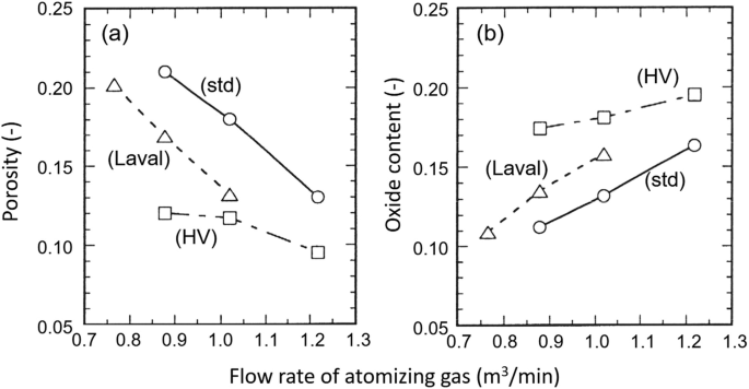
(a) Porosity and (b) oxide content in aluminum coating as function of the atomizing gas flow rate for three different nozzle designs: standard (std), high-velocity cap (HV), and Laval-type nozzle (Laval ), arc current = 200 A, voltage = 34 V (Watanabe et al. 1996)


It should be pointed out, however, that inflight oxidation of the droplets formed during WAS process is not always reflected in the increase of the oxygen content in the coating since, depending on the alloy composition, in-flight droplet oxidation can result in the loss of some of the alloying elements through volatilization. For example, in chrome steel spraying, the formation of a volatile CrO3 can reduce the Cr content from 19% in the wire to 11% in the coating (Wang et al. 1995b). The use of an inert atomizing gas and an inert secondary gas significantly reduces the Cr loss as shown in Fig. 11.22.

Chromium content in wire and in coatings deposited using CO2 atomizing gas with shroud, CO2 atomizing gas without shroud, and air atomization showing the loss of Cr due to volatile oxide formation (Wang et al. 1995b)
In general, the coating microstructure is more uniform with regular lamellae at the higher gas flow rates, and less surface roughness is observed (Wang et al. 1995a; Planche et al. 2003; Jandin et al. 2002). A study of the coating formation through investigation of individual splats (Planche et al. 2004) required preheating of the substrates with an auxiliary heat source, because the splats obtained with cold substrates were extensively fingered and made further analysis difficult.
Jandin et al. (2002) proposed that the coating chemistry can also depend on the atomization gas flow rate. The proposed mechanism is based on the observation that increasing the atomization gas flow rate gives rise to a decrease of the mean size of the atomized droplets with a proportional increase of the specific surface area per unit mass. In-flight oxidation of the droplets being essentially a surface phenomenon will consequently increase with the decrease of the droplet diameter. The results given in Fig. 11.23 offer strong support to this mechanism showing a steady increase of the oxide content of the coating with the increase of the atomization gas (air) flow rate. The reverse trend is observed, when using nitrogen as atomizing gas, where the oxide content of the coating is noted to drop steady with the increase of the atomizing gas flow rate. The authors also note that spraying carbon steel with nitrogen can, on the other hand, result in a reduction in the amount of carbon in the steel due to reaction with nitrogen and an associated reduction in hardness.

Oxide content in carbon steel coating as function of atomizing gas flow rate for air and for nitrogen as atomizing gas. (Jandin et al. 2002)
Increased oxide content usually translates into increased hardness while smaller particle sizes and associated higher droplet velocities result in lower surface roughness and usually better adhesion. An example of the improvement of adhesion is illustrated in Fig. 11.24 giving the elemental composition across the interface between a steel coating and aluminum substrate (Wang et al. 1999). As shown in Fig. 11.24a, the use of a regular nozzle shows a clear difference in the Auger spectrum between the Fe signal of the coating and that of Al signal of the substrate. In contrast, the coating obtained with secondary gas atomization (Fig. 11.24b) shows an intermetallic region, of a few tens of μm thick, between the coating and the substrate where both Al and Fe are present. XRD analysis of this region shows indeed the formation of intermetallic at the interface which is probably due to the higher velocity and higher temperature of the droplet on their impact with the substrate, resulting in local melting of the substrate material .

Auger spectrum across the interface between steel coating and aluminum substrate (a) WAS using a commercial torch with primary gas atomization and (b) WAS with primary and secondary gas atomization (Wang et al. 1999)
Matthews and Schweizer (2013) developed a full factorial experimental design to investigate the effect of four process variables (current, voltage, spray distance, and atomizing air pressure ) on coating quality. Each of these variables had a high and low settings, on the performance of an industrial arc-spray system using 1.6 mm diameter wires of nominal composition Ni-43Cr-0.3Ti with the substrate placed orthogonal to the axis of the torch. The study focused on the impact of these variables on the splat shape and thickness, coating porosity, oxide content, and microhardness. The results showed that:
-
The splat thickness increased with increasing voltage but decreased with increasing gas atomizing pressure
-
High coating thicknesses were generated at high current due to the higher wire feed rate at this setting. Higher gas atomizing pressure and lower voltage also contributed to thicker coatings due to their effect on forming smaller particles which were assumed to have higher deposit efficiency.
-
The coating porosity was reduced at high gas atomizing pressures due to the high-velocity achieved by the small particles generated under these conditions. A complex interaction between the arc current and voltage played a secondary role in the formation of coating porosity.
-
All the variables considered contributed to the amount of oxide formation in the coating. High oxide contents were generated at high gas atomizing pressure, spray distance, and current and low voltage settings. These effects were related to the high surface area of the molten particles generated under these conditions and their residence time in-flight.
-
High coating microhardness was also observed at high gas atomizing pressure and high current settings. This combination of parameters generated high oxide contents and low coating porosities, both of which contributed to the increase in coating microhardness.
Reactive twin-wire arc spraying (TWAS) where each of the two wires is of different composition has as objective the depositing an intermetallic compound of the two wires. According to Chang et al. (2011) when arc spraying Ti and Ni wires fed synchronously into the TWAS gun, some intermetallic compounds such as TiNi3 and Ni-Ti alloy are synthesized in the Ni-Ti coating. The wear resistance of the Ni-Ti composite coating is superior to that of pure Ni-sprayed coating but slightly inferior to that of the titanium. The corrosion resistance of the arc-sprayed Ni-Ti coating is superior to that of Ti but inferior to that of Ni. This is due to numerous microcracks observed on both the surface and the cross section of the Ti coating; see Fig. 11.25a and b. On the other hand, the coating of Ni-Ti is a mixture of white and gray platelets that were identified as Ni and Ti, respectively, by EDS analysis. Cross-sectional SEM micrograph of the arc sprayed Ni-Ti coating is shown in Fig. 11.25c with no visible cracks detectable.

SEM micrograph: (a) Ti coating, surface 5009; (b) Ti coating, cross section 2009; and (c) Ni-Ti composite coating, cross. (Chang et al. 2011)
(Laik et al. 2005) studied metal–ceramic bonding produced by the technique of wire arc–plasma spraying of Ni on Al2O3 substrate, Ni being atomized with argon. The plasma deposited Ni layer shows a uniform lamellar microstructure throughout the cross section. The metal–ceramic interface was well bonded with no pores, flaws, or cracks. An annealing treatment at 1273 K for 24 h of the plasma-coated samples did not result in formation of any intermetallic compound or spinel at the Ni/Al2O3 interface.
2.6 Fume Formation
The high arc temperatures at the wire tips result in some evaporation of the metal or alloying elements. The evaporated metal oxidizes in the surrounding air, and the oxide is quenched to form ultra-fine nano-sized particles (fumes). The lower the boiling point of the metal, the larger the fume formation. These particles represent serious health hazard and require protective measures for the operator and the environment by operating in well aerated booth units equipped with adequate heppa filters and the use of personal protective equipment’s such as respirators. Figure 11.26 (Watanabe et al. 1995) shows the aluminum vapor as observed with a CCD camera equipped with a narrow band filter having transmission at the 313 nm atomic aluminum line, with a 100 ns exposure time. The wire tips are on the lefthand side (LHS), the cathode wire in the top position. There is more evaporation observed from the cathode wire, and the evaporation strongly increases with the increase of the arc current.

Photograph of aluminum vapor in front of the wire tips (not seen at the LHS). The vapor was observed using a line filter for Al line and a high-speed CCD camera. (Watanabe et al. 1995)
Figure 11.27 (Watanabe et al. 1995) shows the relative increase in fume formation with increasing arc current and the relative reduction of fume generation when using a Laval-type nozzle and nitrogen as atomizing gas. The stronger evaporation from the cathode is due to the higher current and heat flux densities at the cathode resulting in higher droplet temperatures. Use of nitrogen as atomizing gas and combined with a nozzle design that increases the gas velocity at the wire tips reduces the fume formation, as shown in Fig. 11.27 (Watanabe et al. 1995)

Intensity of Al vapor spectral light emission as function of arc current atomization with air and N2 using (a) standard and (b) Laval type nozzle with air, in straight and reverse polarity (RP),and N2, pressure = 276 kPa. (Watanabe et al. 1995)
3 Equipment Design and Operating Parameters
3.1 Conventional Twin-Wire Arc Spraying
Compared to other spray processes, arc spraying presents a higher deposition rate with values ranging, dependent on current (100–360A), from 3 to 15 kg/h for Al, 4.5 to 17 kg/h for stainless steel, to 10 to 33 kg/h for Zn. Considerably higher deposition rates, up to 200 kg/h, can be achieved with higher power installations (Steffens et al. 1990).
The main requirements for the material to be sprayed by the wire arc spray process are that the material must be electrically conducting and that it can be obtained in form of a wire without being too brittle or too stiff. Many metals or alloys fulfill this requirement. Therefore, the material to be sprayed is selected according to the application, for which the drawbacks of wire arc spraying, such as relatively high porosity and oxide contents, are less important than its advantages in terms of high deposition rates, low substrate heating, and overall favorable process economics.
A typical twin-wire arc spray setup is shown in Fig. 11.28. It is composed essentially of four main components:
-
The DC power supply
-
Dual wire rolls or spools and wire feeding mechanism
-
Control unit for power supply, wire feeding, and atomizing gas (air)
-
Plasma torch and its traverse moving mechanism

Schematic of twin-wire arc spray (TWAS) system with power supply , control unit, wire supply rolls, compressed air line, and torch
The power supply is usually a thyristor-controlled DC rectifier which must be able to withstand occasional shorting of the output when the wires touch. Since the electrodes are consumable resulting in a varying arc length, the rectifier uses voltage control rather than current control as in conventional DC plasma spraying systems. The desired voltage is set, and when the melt rate of wires is higher than the feed rate, the arc voltage will increase surpassing the set point; the power supply control will respond by reducing the arc current, and therefore the melt rate until the set voltage value is again reached. Alternately, when the arcing gap gets too small resulting in too low voltage values, or if the wires even touch resulting in a momentary short, the current will increase to increase the melt rate. However, since the loss of a metal droplet from the wire tips usually leads to a stepwise change in the arc voltage, one has continuous fluctuations of the arc voltage and arc current as can be observed in Fig. 11.29 with the principal frequencies varying between 500 and 2000 Hz. These fluctuations can be minimized by judiciously adjusting the arc voltage, the wire feed rate, and the atomizing gas flow. Misalignment of the wire guides such that the two wires do not extend to a single point can also lead to voltage fluctuations, as can a movement of the wire tips due to a remaining kinks or cuts in the wires. Most wire arc spray operations are performed with voltage settings below 40 V, with an open circuit voltage requirement between 60 and 80 V. It is to be noted that the response of the power supply to the constantly varying load can influence the coating quality (Marantz and Marantz 1990). The “current control” knob on the power supply controls the wire feed rate, because for a given voltage , higher wire feed rates require higher arc currents.

Illustration of voltage (bottom) and current (top) signal in WAS system
The wire spools are necessarily made of ductile and electrically conductive material taken from a large spool. In order to reduce the wire curvature (cast and kink), the wire is frequently run through a wire straightener, consisting of an assembly of rolls forcing the wire through a straight path. Without the straightener, the wire tips will have a periodic movement resulting in uneven melt rates. The wire transport rollers are either in the control unit, pushing the two wires to the torch head (push wire feed), or they are mounted on the torch head (pull wire feed). It is also possible to have both a push and pull wire feed for optimal feed speed control and allowing longer distances between the control unit and the torch head (up to 15 m) provided that exact synchronization of the drive motors are assured .
The control unit allows adjustment of the operating voltage, the wire feed rate via the feed motor speed, and the pressure of the atomizing gas in the line to the torch. The gas is fed from a compressor or high-pressure gas tanks at pressures of at least 0.6 MPa. Air is the most commonly used atomizing gas, although nitrogen and CO2 are being used as well.
The wires arc torch is of a relatively simple air-cooled design in which the wires are guided inside coaxial hoses to the spray torch, with the metallic layer surrounding the plastic wire guide serving as the power conduit (see Fig. 11.30). The gas supply tube connects the control unit with the torch. The nozzle providing the high-velocity gas flow directed toward the wire tips. Alignment of the contact tips such that the two wires meet is important for obtaining steady melt rates.

Schematic of a twin-wire arc spray (TWAS) torch head (reproduced with kind permission of Carlson RR 2001)
The primary atomizing gas nozzle consists usually of a straight bore operating under choked flow conditions, meaning that the flow velocity in the tube reaches sonic velocity. Alternate torch designs such as that of Praxair TAFA, Fig. 11.31, have a secondary gas flow, i.e., a portion of the atomizing gas flow is diverted to flow around the wire guides to the wire tips. A second nozzle (air cap) is mounted surrounding the wire tips or right upstream of the tips This secondary nozzle is reported not only to improve the atomization providing higher gas velocities at the wire tips but can also be used to reduce the jet divergence. The liquid metal atomization process is strongly dependent on the gas velocity and the fluid dynamic design of the torch which affect significantly the coating quality .

Schematic of twin-wire arc spray (TWAS) torch head with primary and secondary gas flow. (Reproduced with kind permission of Praxair TAFA)
An example of a typical, general purpose WAS unit by Oerlikon-Metco, Model Flexi ArcTM300, is show in Fig. 11.32. It is commercialized for applications of standard coatings with high output rates. It features maximum current rating of 300A and use of handheld spray gun (LD/U2) with a pneumatic push/pull wire feed system .

General view of an Oerlikon Metco Flexi Arc™ 300 wire arc spray unit. (Reproduced with kind permission of Oerlikon Metco)
Typical operating parameter ranges of WAS units in general are listed in Table 11.2. It should be noted that high-power twin-wire arc coating installations exist operating at arc currents up to 1500 A. These installations which require water-cooling of the contact tips are mainly used for anti-corrosion coatings on large surfaces.
3.2 High-Velocity Twin-Wire Arc Spraying
A different nozzle design aiming at significantly increasing the droplet velocities has been proposed by (Hussary et al. 1999). The study involved the modification of commercial Miller Thermal (now Praxair TAFA) BP 400 by replacing its upstream nozzle by a Laval-type nozzle with the wire tips at the nozzle exit plane (CDCP) as shown in Fig. 11.33a. The nozzle design and dimensions were based on compressible flow computations for the specific operating conditions. A ring of small orifices was also added surrounding the nozzle and providing a shroud gas flow , as shown in Fig. 11.33b, with the orifices angled toward the jet axis. Two different angles were proposed (SCDCP1 and SCDCP2) (Hussary 1999).

Schematic of (a) Laval-type nozzle surrounding wire tips; (b) gas shroud arrangement. (Hussary 1999)
Further development of the standard twin-wire arc spraying torch design involved the use of a high-velocity gas stream to atomize the arc-melted material at the tip of the wires and propel the droplets toward the substrate surface. The gas stream velocity conditioning the droplets impacts velocity and thus the splats diameters and thicknesses and consequently the coatings properties. As demonstrated by different authors (Kelkar and Heberlein 2002; Liao et al. 2005; Chen et al. 2012; Wu et al. 2014), high impact droplet velocities will result in better coating properties. The principle used to achieve high-velocity particles is presented in Fig. 11.34 where the gas injection is achieved with a convergent–divergent nozzle.

Schematic of the original HAS-01 type torch configuration . (Chen et al. 2012)
A novel design of the torch head configuration was put forward by Chen et al. (2012) based on 3-D modeling of the flow field around the wire tip, the arc, and molten metal atomization region. A schematic representation of the proposed geometry for the wire guides, and the profile of the gas atomization nozzle is shown in Fig. 11.35. When comparing the velocity developments along with spray distance for the droplets with different sizes, it was predicted that higher velocities and a shorter acceleration distance would be obtained for the smaller droplets. For most moderate size droplets, their velocity increased rapidly in the early stages of their trajectory reaching a rather stable value for the remaining of their trajectory until their impact on the substrate. Experiment measurements of the droplet velocities along their trajectories were in good agreement with the modeling results.

Schematic of the newly designed twin-wire arc spray (TWAS) torch head configuration. (Chen et al. 2012)
3.3 Single-Wire Arc Spraying
A typical design of single-wire arc spraying (SWAS) torch is given in Fig. 11.36 after Marantz et al. (1991). This designed, often referred to as plasma transferred wire arc spraying (PT-WAS) , is based on the use of a non-consumable thoriated tungsten cathode coaxially placed at the at the center of an air-cooled copper nozzle, with consumable-wire anode placed at 90° to the torch axis downstream of the nozzle exit. The arc is initiated by a high-frequency ignition between the cathode and the nozzle, followed by the transfer of the arc to the consumable-wire anode. The plasma gas is preferably argon–hydrogen mixture, though other gases have also been used including air and nitrogen, which is injected in the annular space between the cathode and the copper nozzle. A secondary gas injected as a series of high-velocity micro-jets surrounding the central arc nozzle serves to atomizing molten metal formed at the tip of the wire (Cook et al. 2003). It also serves as shroud gas for narrowing the molten droplet spray pattern (Marantz et al. 1991; Kowalsky et al. 1992).

Schematic of plasma transferred wire arc spraying (PTWAS) torch. (Marantz et al. 1991)
A constant current power supply is used, with currents ranging from 20 to 100 A, with typical operating voltages of around 120 V. Compared to twin-wire arc spraying, smaller droplet sizes are generated resulting in a finer grain structure of the coating comparable to that of plasma-sprayed coatings . The position of the wire tip can be adjusted by adjusting the operating parameters (current and wire feed rate) as an additional control of coating quality. Typical plasma gas flow rates are in the range of 51 to 71 slm, while considerably higher flow rates are needed for the secondary/shroud gas in the range of 621 to 793 slm (Kowalsky et al. 1992). Droplet velocities, measured using laser Doppler anemometry, are in the range of 80 to 125 m/s varying depending on the wire material and nature of the atomizing gas. The arc current has little effect on the droplet velocity.
A modified version of the PT-WAS torch, schematically illustrated in Fig. 11.37, was developed for the coating of inner walls of the cylinders in automobile aluminum engine blocks which can have an inner diameter as small as 75 mm (Marantz et al. 1991; McCune Jr. et al. 1993; Cook et al. 2003). The small-sized, rotating atomization module allowed for the uniform coating of the wall of relatively small engine cylinders. This development which targeted automotive applications had to comply also with the need of good coating adhesion as a prime concern, which could be achieved using a pretreatment with a fluoride-based flux and a NiAl bond coat before the final low carbon steel coat is applied (Cook et al. 2003). Coatings with less than 2% porosities were reported with excellent adhesion to the substrate.

Schematic of plasma transferred wire arc spraying (PTWAS) torch developed for the coating the wall of cylinder bore. (Marantz et al. 1991)
A different approach for the design of the PT-WAS torch was proposed by Steffens and his research group at the University of Dortmund, (Steffens and Wewel 1991; Steffens and Nassenstein 1994). As schematically illustrated in Fig. 11.38, the proposed design was closer to a conventional DC plasma torch with the feed wire (1.6 mm diam.) acting as cathode, centrally located in a water-cooled anode nozzle 2.4 mm i.d. surrounding the tip of the wire. The arc is initiated by an RF discharge and operated with a constant current power supply at arc currents between 100 A (for stainless steel) and 140 A (for Ti). The arc voltage ranged from 30 to 45 V. The process known as single-wire vacuum arc spraying (SW-VAS) was mostly developed for the spraying of high purity coatings of Ti or Ta, since a single wire as coating precursor material offers the lowest chances of surface contamination. The spraying was performed in a controlled atmosphere mostly under reduced pressure (10–80 kPa) with Argon as atomizing gas at flow rates of 158 slm. Maximum wire feed had to be dropped sharply from 3.5 m/min to less than 2.0 m/min with the increase of the chamber pressure from 10 to 80 kPa to maintain the quality of the coating. The corresponding metal spraying rate in this case would be around 1 kg/h (Ti) and 1.8 kg/h (steel). Coating porosity, on the other hand, was observed to increase from less than 3% to above 10% with the increase of the camber pressure over the same pressure range.

Schematic of a single-wire vacuum arc spray (SW-VAS) torch. (Steffens and Nassenstein 1994)
A similar approach was used by Heberlein and his research group at the University of Minnesota for the development of the high-definition single wire arc spray (HD-WAS) torch (Carlson et al. 2000; Carlson and Heberlein 2001, 2002). As schematically illustrated in Fig. 11.39a, the wire, which in this case acts as anode, is surrounded by a nozzle at a floating voltage. A tungsten rod attached to the downstream face of the nozzle serves as cathode. A constant current welding power supply was used with typical arc currents between 35 and 125 A and voltages are between 19 and 22 V. Argon was used as the atomizing gas with backpressures between 100 and 400 kPa above the atmosphere. This development was mainly pursued for obtaining a narrow particle stream for high-definition coating of small areas such as valve seats. Figure 11.39b (Carlson 2005) shows the particle stream exiting the device. Measured divergence angles are between 2 and 3 degrees, slightly increasing with higher currents and higher back pressures. The wire is fed through a wire straightener before entering the torch to assure minimal lateral movement of the wire tips.

Results have been reported using mild steel wires , 0.584 and 0.762 mm, diameter at feed rates between 3 and 8.4 m/min with matching arc currents of 35 and 125 A. The gas nozzle diameter is typically 2.5 to 3 times the wire diameter. Droplet sizes are significantly larger than in any other thermal spray process, with typical mass mean diameters in the order of 300 μm. Figure 11.40 shows corresponding droplet/particle size distributions obtained by spraying into water for these two wire sizes.

Droplet size decreases with increasing backpressure and decreases slightly with increasing current. Figure 11.41 (Carlson and Heberlein 2001) shows examples of traces sprayed with this torch, and it is seen that with the smaller wire diameter and the lower back pressure, the deposition foot print is about 3 mm wide. The coating cross sections show dense equiaxed material without the layer structure typical of any other spray coating (see Fig. 11.42) (Carlson and Heberlein 2001). Deposition efficiencies are between 75 and 86%, larger for the larger wire size and for higher currents. Deposition rates are up to 15.6 g/min for the smaller diameter wire and up to 25.8 g/min for the larger diameter wire.

Photograph of mild steel deposit traces on Al substrates for two different wire diameters (a) wire diam. =0.584 mm, feed rate = 4.9 m/min (b) wire diam. =0.762 mm, feed rate = 8.4 m/min, and two different and atomizing gas back pressures, 141 and 272 KPa..(Carlson and Heberlein 2001)

4 Gas and Particle Dynamics in Wire Arc Spraying
4.1 Particle Velocity and Flux Distribution
The velocity of the droplets/particles at the exit of the atomization zone are closely dependent on the velocity of the atomizing gas in the arc region between the two-wire tips, or between the wire and auxiliary electrode tip depending on the torch configuration. The atomizing gas velocity reflects, in-turn:
-
Upstream pressure of the atomizing gas
-
The primary atomization nozzle shape, i.e., Laval-type nozzle vs. straight bore nozzle
-
Secondary nozzle around the wire tips (“high-velocity cap”)
-
Secondary gas flow rate along wire guides
-
Shroud gas flow rate from a secondary nozzle
Schlieren images of the region between the atomizing gas nozzle exit and the wire tips in a twin-wire arc spray torch are given in Fig. 11.43 (Hussary 1999) for air supply pressures of 482 kPa (70 psig), 550 kPa (80 psig), and 826 kPa (120 psig). These clearly reveal well-defined shock diamonds which are due to an under-expanded flow pattern exiting the atomizing gas nozzle at sonic velocity. Results of pitot tube velocity measurements in a cold compressed air flow, in the absence of arcing, at the location of the wire tips (50 mm from the nozzle exit) are given in Table 11.3 (Hussary 1999). The results obtained using a straight bore nozzle “regular , “and a converging–diverging “Laval-type” nozzle show that for an identical gas supply pressure of 450 kPa (65 psig), the exit gas velocity can be increased to supersonic values of 352 m/s (Mach number = 1.02) with the use of a “Laval-type” nozzle.

Schlieren images of shock pattern outside atomizing gas nozzle showing under-expanded flow exiting straight bore nozzle. (Hussary 1999)
It should be noted that despite the choked nozzle flow conditions the mass flow rate of the atomizing gas will increase with the increase of the upstream pressure because the gas density increases and some of the gas is diverted to flow along the wire guides. Both effects will increase the shearing actions on the liquid metal film resulting in smaller droplet sizes.
Measurement of droplet velocities have been reported in wire arc spray conditions using streak photography (Wang et al. 1996) and the DPV-2000 (Hussary 1999) in-flight particle diagnostic techniques. Figure 11.44 shows the axial distributions of the centerline velocity of aluminum droplets atomized using a BP 400 twin-wire arc spray torch operating at 100 A and 30 V for different supply gas pressures of 276 kPa (40 psig), 344.5 kPa (50 psig), 413.5 kPa (60 psig), and 482.3 kPa (70 psig). The corresponding atomizing gas flow rates were respectively, 750, 935, 1133, and 1331 slm. The results further confirmed that the increase of the supply pressure is responsible for the increase of the droplets velocities which reaches its maximum value at 50 to 100 mm from the nozzle exit level. Velocities averaged over the cross section and weighted by the droplet number density at radial locations were, however, almost 10% lower than the peak values over the axis of the torch due to lower velocity particles in the fringes of the jet.

Axial droplet velocity profiles for different atomizing gas pressures. (a) Axial velocity distribution along the centerline of the jet (b) Average velocity over the cross section weighted by local droplet flux (Hussary 1999). (Reproduced with kind permission)
Special attention was also given to the effect of the atomizing gas nozzle design on the axial velocities of the generated droplets. Figure 11.44 (Hussary et al. 1999) shows the axial distributions of the droplet velocity along the center line of the jet and the flux-weighted average velocities for aluminum droplets generated using a modified BP 400 torch. For comparison, values obtained with the standard commercial torch/nozzle configuration are included identified as “com.” A modified version of the torch illustrated earlier in Fig. 11.33a, was also tested. It involved the elimination of the upstream nozzle and replacing it by a Laval-type nozzle with the wire tips at the nozzle exit plane. The results obtained with this nozzle are identified as “CDCP” nozzle on Fig. 11.45. A second modification tested, identified in Fig. 11.45 as “SCDP1 and SCDP2” involved the addition of a ring with small orifices surrounding the nozzle at two different angles providing a shroud gas flow as illustrates in Fig. 11.33b. The results show that the Laval-type nozzle (CDCP) provides a significant increase of the average and maximum droplet velocities compared to the standard torch design “com.” Furthermore, the use of a shroud, whether of the “SCDP1” or “SCDP2” designs further increased the measured droplet/particle velocity. Hussary (1999) reported that the use of the modified nozzle and the shroud gas significantly reduces the divergence of the droplet jet as shown in the Schlieren images of the particle jet given in Fig. 11.46 and the r0.5 values given in Fig. 11.47. The latter represent the radial location at which the droplet flux reached a value corresponding to 50% of its maximum value on the jet axis. The narrowing of the divergence of the droplet jet is illustrated in Fig. 11.48 by the profile of the “footprint” deposited on a stationary substrates, commonly referred to as the “sweet spot” (Hussary 1999).

Axial distributions of the maximum and weighted-average aluminum droplet velocities for different nozzle designs. (Hussary et al. 1999)

Schlieren images of Al spray droplet jet for different nozzle designs: (a) commercial nozzle with cap “com,” (b) Laval-type nozzle “CDCP,” and (c) Laval-type nozzle with additional shroud gas “SCDP1” (Hussary 1999)

Radial location of r0.5 where the local mass flux is 50% of the maximum at three different axial locations and for four different nozzle designs. (Hussary et al. 1999)

Aluminum “footprint–sweet spot” deposit on stationary substrate with four different nozzle designs. (Hussary 1999)
Measurements of the velocities of carbon steel droplet sprayed by a TAFA-9000 system with a converging nozzle and secondary gas flow, operated at 100 A, 30 V for a range of atomizing gas flow rates varying from 90 to 150 m3/h (1500–2500 slm) obtained using a DPV-2000 are given in Fig. 11.49 (Jandin et al. 2002). The corresponding droplet/particle diameter distributions were obtained by spraying into oil and measuring the particle diameter using optical or electron microscopy.

Average carbon steel droplet velocity (top) and diameter (bottom) as function of atomizing gas flow rates with converging nozzle in cap and secondary gas flow. (Jandin et al. 2002)
This study was further extended by Planche et al. (2003, 2004) with the objective of formulating an empirical correlation between the droplet characteristics and various operating parameters and spatial locations in the jet. The arc current was varied over the range 100 to 200 A, with a total atomizing air flow rates from varied from 1500 to 2167 slm, axial spray distances from z = 200 to 300 mm, and horizontal (x) and vertical (y) variations of up to 20 and 30 mm from the spray axis, respectively. The following relationships have been found for I in A and \( \dot{\mathrm{Q}} \) in m3/s (Planche et al. 2004) relating the droplet properties temperature, velocity, and diameter with the operating parameters and the position in the jet, given by the coordinates x (perpendicular to the spray direction and perpendicular to the plane of the wires, zero on the torch axis), y (perpendicular to the spray direction and in the plane formed by the two wires, zero again being the torch axis), and z the axial coordinate with zero being the torch exit, all coordinates measured in m:
Velocity in (m/s)
Temperature in (K):
Droplet diameter in μm:
It is interesting to note the strong inverse correlation of droplet diameter with atomizing gas flow rate. The stronger acceleration due to lower mass appears to offset the lower drag due to a smaller cross section, resulting in an almost linear increase of the droplet velocity with atomizing gas flow rate.
Similar measurements were reported by Pourmousa et al. (2004, 2005) using a commercial twin-wire arc spray system (ValuArc from Sulzer Metco) operated at 32 V, aluminum wire feed rate of 7 m/min, and atomizing gas supply pressure of 208 kPa (30 psig) with a corresponding air flow rate of 1032 slm. The results given in Fig. 11.50, obtained with a DPV-2000 instrument at 50 mm from the wire tips, are presented in terms of droplet/particle velocity profiles, mean particle diameters distributions, and the normalized mass flux distributions along two orthogonal axis x and y, with the y plane being that of the two wires in the torch. The results show reasonable spatial symmetry of the distributions in the x and y directions with the maximum droplet/particle velocity of about 100 m/s on the axis of the jet. The mean droplet/particle diameter does not seem to change excessively in the measurement plane with the droplets/particles in the fringes having a slightly larger diameter compared to those moving along the centerline of the jet. Particle flux distributions drops significantly with distance from the axis of the jet covering a spraying area of about 50 mm in diameter.

Lateral profiles of (a) droplet velocity, (b) mean droplet diameter, and (c) normalized mass flux, of aluminum droplets, along x (left) and y (right) directions, at an axial location of 50 mm from the nozzle exit. The wires are in the y plane. (Pourmousa et al. 2005)
The spraying of chrome steel wires using air as atomizing gas and secondary shroud gas was reported by (Wilden et al. 2007b). Operating parameters were varied from 24 to 36 V, 100 to 300 A, and gas supply pressures from 200 to 400 kPa. The droplet velocity was strongly affected by the gas supply pressure increasing from about 75 m/s to about 130 m/s for 32 V 100 A operation (not quite a proportional increase as predicted by Eq. 11.3). Increasing the arc current resulted in a slight decrease of the droplet/particle velocity (from about 130 m/s at 100 A to about 115 m/s at 300 A and 32 V, 400 kPa). This effect could be explained by a larger droplet diameter at higher currents in qualitative agreement with Eq. 11.3. The effect of voltage on droplet velocity was negligible, though considerably more pronounced on droplet temperatures.
A study of droplet velocities and temperatures for nine different wire materials and different nozzle sizes was reported by Mohanty et al. (2003). A TAFA 8830 torch was used with different caps, operated at 200 and A 36 V with air or nitrogen as atomizing gas at a flow rate of about 1420 slm. At 160 mm from the nozzle, the average velocities ranged from about 90 m/s for Ni to about 115 m/s for NiAl and about 121 m/s for Mo, with the droplet/particle velocities of different types of steel and copper essentially in the same velocity range. No direct relationship with material properties is reported. No significant difference in droplet velocity was found when nitrogen gas was used instead of air. It is to be noted that droplet velocities are strongly influenced by the torch design and optimizing droplet velocities will require evaluation of the fluid dynamics inside the torch.
4.2 Particle Temperature
In contrast to metal particle velocity and flux distributions which are strongly affected by the fluid dynamics of the flow, droplets/particles temperatures generally slightly above the melting temperature of the material. During particle flight in the atomizing gas jet, the particle surface temperature can increase due to surface oxidation resulting from their contact with the atomizing air. In-flight temperature measurements of aluminum droplets have often been reported as being as high as the melting point of Al2O3, 2045 °C, because the surface of the droplet is oxidized. It also must be mentioned that wire arc spray droplets are in a condition where convection-induced oxidation has been observed with oxide content more than 20% for aluminum coatings, as in plasma spraying. This effect of internal convection can explain the very high oxide content values more than 20% observed with aluminum coatings, and the increase of the oxide content with atomizing gas flow rate is also expected because of the convection of the oxide inside the particle.
As seen from the empirical relation Eq. 11.4, the droplet temperature does not change very much with arc current, atomizing gas flow rate, and horizontal or vertical position, and only a gradual decrease with axial distance is seen. Jandin et al. (2002) report a wider spread of droplet temperatures for smaller particles (less than 20 μm diameter), i.e., at higher atomizing gas flow rates. Pourmousa et al. (2004, 2005) report temperatures of Al droplets decreasing from 2160 °C to 2130 °C with an increase of the supply pressure from 236 to 542 kPa with little variation in the horizontal or vertical direction. Wilden et al. (2007a) report an increase in the temperatures of chrome steel droplets from 2070 to 2180 °C when the arc voltage was increased from 24 to 36 V; however, little change of droplet temperatures with current is found, consistent with Eq. 11.3. All temperatures reported indicate a superheating of the droplets significantly above their melting points. For example, Mohanty et al. (2003) report temperatures of about 2275 °C for stainless steel, about 2370 °C for Ni (melting point 1455 °C), about 2610 °C for Cu (melting point 1085 °C), and about 2860 °C for Mo (melting point 2617 °C); all obtained for 32 V, 200 A operation. While no significant dependence on atomizing gas flow rate is seen, a significant effect of the atomizing gas is observed, with steel droplets showing temperatures of about 2600 °C when atomized with air compared to about 2430 °C when atomized with nitrogen. This effect is probably due to oxidation providing additional heat. The observation that droplet temperatures increase somewhat for higher gas flow velocities obtained through a different nozzle, i.e., with smaller droplets, supports this conclusion .
The lack of dependence on arc current is clear if one considers that the arc current is an indication of wire feed rate, and increased power by increasing the current is used for higher melting rates. The increase in droplet temperature for increasing arc voltage can be explained by the high-speed video observations that increased arc voltage allows the arc to bow more in the downstream direction and to provide more heat to the extended metal ligament. Operation at low arc voltages can result in solidification of particles, particularly when coating at larger standoff distances. There are no droplet temperature measurements that separate the droplets originating from the cathode and those from the anode. The higher current densities at the cathode would lead one to expect higher droplet temperatures. The higher droplet temperatures observed by Jandin et al. (2002) for small droplet sizes may be an indication for a temperature difference between the cathode and the anode droplets.
4.3 Process Modeling
Only a few models have been formulated for the wire arc spray process because of its complexity, requiring by nature three-dimensional, time-dependent treatment, including phase change of the metal electrode and atomization of the liquid metal. One modeling effort has split up the problem into several separate parts:
-
Compressible flow model for the atomizing gas flow upstream of the arc
-
3-D model of an arc in cross flow (steady state), with different anode and cathode attachments, yielding temperature, and velocity fields
-
2-D turbulent plasma jet model
-
Liquid metal atomization models for the cathode and for the anode and a secondary atomization model (Kelkar et al. 1968; Kelkar and Heberlein 2000, 2002)
The compressible flow model provided input for the arc in cross-flow model, and this model was verified with some previously published experimental data as well as some data obtained for a wire arc configuration but without consumable electrodes and using enthalpy probes to determine plasma temperatures and velocities. Figure 11.51 (Kelkar and Heberlein 2000) shows the temperature and velocity distribution in the center plane of the arc. The model captures the differences between the arc anode and cathode attachments, with higher temperatures and velocities at the cathode. But it shows that 5 cm downstream of the electrodes the flow is essentially axisymmetric, justifying a 2-D model for the jet region.

Computed (a) velocity (m/s) (b) temperature (K) in the mid-plane of an arc with cross flow (from the bottom). (Kelkar and Heberlein 2000)
The cathode atomization model is essentially a model as developed for metal welding arcs, whereas the anode atomization model uses the boundary layer stripping of the liquid metal sheets and the breakup due to the Kelvin–Helmholtz instability . The secondary breakup model follows an empirical relationship developed by Hsiang and Faeth (1992).
Figure 11.52 (Kelkar and Heberlein (2002) shows calculated particle velocities as function from the distance from the wire tips for different particle sizes. Also shown in the figure are two measured particle velocities using the DPV-2000 and their respective sizes, showing a surprisingly good agreement considering the modeling simplifications.

Computed axial droplet velocity profiles for different droplet diameters. For comparison, two experimentally determined (DPV-2000) droplet velocities are included. (Kelkar and Heberlein 2002)
Figure 11.53 (Kelkar and Heberlein (2002) show the calculated droplet size distributions (bars) compared to experimentally measured ones (squares) for two different nozzle inlet pressures The shape of the size distribution, going from a bimodal to an almost mono-modal distribution when the nozzle inlet pressure is increased from 300 kPa to 430 kPa, is well replicated and shows the increased importance of secondary atomization. However, the calculated sizes are smaller than the measured ones. Clearly, more effort is required for a complete modeling description of the wire arc spray process.

Modeling results (bars) and measured (squares) of the droplet size distributions as function of atomization gas pressure (a) 300 kPa, (b) 430 kPa. (Kelkar and Heberlein 2002)
Several CFD calculations were performed for simulating the performance of the TAFA 9000 torch and for optimizing the nozzle designs. Bolot et al. (2001)used the commercial PHOENICS code to simulate the exact configuration of the torch. The effect of the arc on the flow was neglected. Measured relationships between gas flow rate and upstream pressure were used. The results show the gas velocity distributions inside the torch and in the jet. Figure 11.54 (Bolot et al. 2001) shows as an example calculated horizontal and vertical distributions of the axial velocity, indicating the difference.

Computed radial distributions of the axial gas velocity 25 mm from the nozzle exit for two symmetry planes, vertical (plane of the wires) and horizontal, showing the broader profile in the plane perpendicular to the wires. Gas flow rate 1833 slm (gas supply pressure 285 kPa). (Bolot et al. 2001)
The power required to melt the wires at a given feed rate and to heat the droplets was estimated to be 65% of the electrical input power. A 2-D version of PHOENICS was used to identify nozzle geometries for the same torch that would yield increased droplet velocities (Gedzevicius et al. 2003). Several designs of the nozzle surrounding the wire tips were simulated, and a design was chosen that had an extension of the nozzle in the downstream direction with a constant cross-sectional area. Experiments performed with such a modified nozzle demonstrated an increase in the droplet velocity by about 20%. The velocity distributions for the three configurations of the TAFA 9000 torch shown in Fig. 11.11 and particle velocities were obtained considering different droplet sizes and acceleration by the gas with the calculated velocity (Planche et al. 2003), again using the PHOENICS code . The results are shown in Fig. 11.55 (Liao et al. 2005) where the gas velocities and the velocities of droplets with three different droplet sizes (10, 51.7 and 70 μm) are displayed for two different nozzle arrangements, the Laval-type nozzle without cap (open configuration) and the Laval-type nozzle in the cap. The advantage of having the peak of the gas velocity at the location of the wire tips in the case of the cap is shown clearly, leading to a better acceleration of the droplets.

Calculated centerline atomizing gas and droplet velocities for three droplet sizes of 10, 51.7, and 70 μm (a) the arrangement of a Laval type atomizing gas nozzle without cap, and (b) for a secondary nozzle (cap) with Laval type nozzle. (Liao et al. 2005)
A similar approach but based on the commercial code FLUENT with a k-ε turbulence 3-D model was again applied to the TAFA 9000 torch (Bolot et al. 2008). The wire material, TAFA 38 T 1.6 mm Mn-steel wire was assumed to be heated to the boiling point (3133 K) and use of experimentally determined droplet size distributions avoided the requirement of an atomization model. Gas and steel droplet velocity distributions were calculated for an atomization air pressure of 0.414 MPa (60 psig), air flow rate of 1680 slm, arc voltage of 31 V, and arc currents varying between 100 and 250 A. The corresponding wire atomization rate was estimated at 2.62 to 9.35 kg/h with mean droplet sizes of 18.8 to 20.5 μm, for arc currents of 100 and 250 A, respectively.
Computations were carried out of the gas flow and temperature fields including particle trajectories and gas particle loading effects. Typical results given in Fig. 11.56 and 11.57 obtained for an arc current of 100 A, 2.62 kg/h wire atomization rate show respectively the gas velocity fields and particle trajectories in two orthogonal planed over an extended region of interest of 200 mm downstream of the WAS torch. No particle loading was considered in this case. Figure 11.56 shows the velocity magnitude increases along the primary nozzle with air flowing through the secondary path around the primary nozzle. There is a very high-velocity region just at the wires meeting point which forms a horizontal V shape in the vertical plan (i.e., perpendicular to the plan of the wires). A strong difference in the jet divergence in the vertical and horizontal plans is also noticeable. In particular, the jet divergence is much more pronounced in the plan of the wires than in the vertical plan. Figure 11.57 shows the droplet trajectories viewed in the two orthogonal plans. The particle jet divergence in the vertical plan (Fig. 11.57a) is lower in comparison with that observed in the plan of the wires (Fig. 11.57b). The range of particle velocity is comprised between 50 and 220 m/s at the distance of 200 mm. Computations were also carried out at higher arc currents and consequently higher atomized droplet loading in the gas jet (9.35 kg/h at 250 A). These show an increasing “loading effect” with the axial gas velocity suppressed by 50 m/s at a location 30 mm downstream from the nozzle exit when the interaction with droplets was considered. The effect became less noticeable at farther downstream locations. Again, a different divergence of gas velocities and particle trajectories is observed, with a larger divergence angle in the plane of the wires. This observation is in contrast to that of (Pourmousa et al. 2005) who observed a larger jet divergence in the plane perpendicular to the plane of the wires, but with a different spray torch. Figure 11.58 (Bolot et al. 2008) shows a comparison of the calculated droplet velocities with measured (DPV-2000) for an arc current of 100 A. The error bars represent standard deviations. Good agreement is seen for the smaller droplet sizes.

Gas velocity mapping in two orthogonal plans for WAS TAFA 38 T steel wire atomization, air pressure = 0.414 MPa (60 psig), arc current =100 A, (a) vertical plane, (b) horizontal plane. (Bolot et al. 2008)

Droplet trajectory mapping in two orthogonal plans for WAS TAFA 38 T steel wire atomization, air pressure = 0.414 MPa (60 psig), arc current =100 A, (a) vertical plane, (b) horizontal plane. (Bolot et al. 2008)

Comparison of calculated and measured particle velocities for different particle sizes, arc current = 100 A. (Bolot et al. 2008)
Chen et al. (2009b) presented a CFD model for a wire arc spray gun, to optimize the configuration parameters on the basis of numerical simulation. The FLUENT commercial code was used to study the gas flow inside and outside the spray gun. A comparison between the converging nozzles and converging/diverging nozzles was done to analyze the gas flow dynamics distributions. The compression wave and expanding phenomenon of the converging–diverging nozzle were relatively weaker as compared with the converging nozzle. For the optimized converging–diverging nozzle with varying inlet pressures, from 0.4 MPa to 0.6 MPa, the gas velocities in the core of the spray jet were still kept at high values even if the spray distance was about 200 mm. They showed that other parameters were also important, such as the distance from the two wires’ intersection point to the nozzle exit and the wires intersection angle, because they significantly affected the dynamics properties of the external gas flow. The 3-D model provided an analysis of the above configuration parameters. The results showed that moving the intersection point from the nozzle outside to the nozzle exit and that moderate intersection angle was better for the flow velocity distribution and droplets atomization. Results allowed modifying the gun design to upgrade the original HAS-01 gun, and the modified design was experimentally compared with the original one by measuring the in-flight droplet size and velocity.
Toma (2013) has also discussed the effects of velocity and temperature of sprayed particles on physical and mechanical properties of coatings. These parameters are in a close relationship with the drive jet velocity and temperature. They made a comparative research of steel (C-0.14, Mn-0.43, Cr-0.3, Ni-0.3, Si-0.15, P0.04 and S-0.04 wt.%) deposits, carried out by two spraying procedures: the classic wire arc spraying procedure plus a new one, which represents a combination between the classic wire arc spraying and the flame spraying procedure. The use of a new procedure allowed the increase of the drive jet temperature and the study of its effect created on deposit properties. The modeling of the arc spraying and the analysis with finite elements in a coupled field allowed the determination of the drive jet temperature variation and the fuel flow, necessary for the temperature to be maintained over 1000 K at spraying distance of 150 mm. The investigations carried out on steel coatings, obtained by this procedure, demonstrate that the spraying jet temperature increase determines the average growth of the coating’s adherence over 18% for cylindrical surface and over 5% for flat surface. Also, these investigations demonstrate the decrease of the average porosity by over 22% for cylindrical surface and by over 17% for flat surface. Because of the difficulty of obtaining reliable gas velocity measurements, these simulations are valuable for optimization of nozzle designs and understanding the atomization and droplet acceleration behavior.
Toma (2013) has compared the classic wire arc spraying procedure with a new one, which is a combination between the classic wire arc spraying and the flame spraying procedure. For steel spraying, it was possible to increase the temperature of the flame up to 2000 K and keep its value above 1000 K at the distance up to 150 mm. The increase in the temperature allowed better melting of the sprayed particles and improving the properties of deposits. The coating porosity decreased by over 22%, for deposits carried out on cylindrical surfaces, and by over 17%, for deposits carried out on flat surfaces. The modification of the spray technique also improved the coatings adherence: 18% for cylindrical surfaces and of 5% for flat surfaces.
5 Applications of Wire and Cord Arc Spraying
As mentioned earlier, wire arc spraying (WAS) is one of the oldest thermal spray technologies that has gained wide acceptance for a broad range of applications because of its flexibility, reliability, and favorable economics compared to alternate more technologies. It is, however, limited to a large extent to metallic coatings for which the feed material is available in the form of flexible ductile wires. The use of cords allowed to a limited degree the extension of the use of the technology to metal-ceramic composites for special applications. Cord arc spraying (CAS) is predominantly used for wear resistant coatings with the hard and brittle compounds used as filler material in low carbon steel sheath. It is also possible to make use of generating alloys in flight or on the surface, such as NiCr with Ni and Cr powders, or compounds like Ni3Al with a Ni and Al powder mixture (Steffens et al. 1990). In this section, a brief review is presented of principal applications of wire arc spraying as tools for functional surface modifications and the rebuilding of worn surfaces or near net-shaped parts.
The large majority of materials used for WAS or CAS are available either as standard wire, 1.6–4.76 mm diameter (1/16–3/16 inch), of pure metals and alloys, or in the form of a cord in the same size range manufactured through the rolling of a thin metal foil in the form of a tube packed with fine powder mix of the required composition of the coating material. An example of some of the materials commonly used in this field and their recommended applications are given in Table 11.4 after (Oerlikon Metco technical bulletin, issue 6).
It may be noted from this table that Corrosion and galvanic protection is one of the most important applications of WAS using mostly aluminum, copper, iron, and nickel and their alloys. Erosion/wear protection and cavitation control comes next using iron, nickel, and their alloys as well as tungsten carbine cords. Iron and its alloys are also used for gripping/antiskid and low friction while Nickel and its alloys for bond and oxidation-resistant coatings. Other applications of varying scope include net shape parts and dimensional restoration, clearance control, electro- and thermoconductance, EMI shielding, biofouling control, and decorative.
A comprehensive review of present and potential wire arc spray technology in China was reported by Liu (2001) who points out that it is the most efficient way for long life corrosion protection of steel structures. The arc spraying process is also used for a wide range of applications such as renovation and surface modification of machine components, mold making for plastic products, high-temperature corrosion resistance for boilers, anti-sliding coatings, and self-lubricating coatings. With the advances and developments in arc spray equipment and spray materials and the simplicity of operation, arc spray technology is used for demanding, high-quality coating applications, which are nearly equivalent to those previously served by alternate plasma technologies at significantly reduced capital and operating costs. Arc spraying is becoming a serious economic alternative to other thermal spraying processes while maintaining, and in many cases improving, the quality of the finished product.
5.1 Corrosion Protection
Corrosion protection is one of the most important industrial applications of wire arc spraying. Basically, two distinct approaches are used to achieve this objective, the galvanic protection or the sealed coating protection. Galvanic is mostly used when the part to be protected is completely or partially immersed in an electrolyte such as sea water, as in most marine applications (ship hulls, decks, or offshore oil drilling platforms). For structures made of mild steel or low alloy steel, the coating materials has to be more electronegative than the base material (−0.6 to −0.7 V) as given in Fig. 11.59 for the galvanic series of elements referenced to saturated calomel electrode (SCE). Zinc (−1.0 V) and aluminum alloys (−0.75 to −1.0 V) with a galvanic voltage lower than those of steel are good candidates for such coatings which is this case can be porous since the coating is sacrificial (cathodic protection). On the other hand, when the potential of the coating material is higher than that of steel, such as nickel (−0.1 to −0.2 V) (anodic protection), the coating needs to be impermeable with no open porosity in order to prevent the corrosive elements to reach the base surface.

Galvanic series of the elements referenced to saturated calomel electrode (SCE)
The wire arc spraying for anti-corrosion protection of the steel structure of ships is typical example. http://www.metallisation.com/ reports on a number of separate projects where a variety of ship were sprayed with pure zinc or a zinc-aluminum alloy (85/15%) including two trawlers, an oceanographic ship, and fish carrier which all external decks superstructures the bridge, mast, and chimney metal sprayed. An example is also given for the wire arc spraying of close to 5000 m2 of its internal and external surfaces with zinc on a 3588-ton Norwegian fishing trawler, (Fig. 11.60). One of the advantages cited is the ease of operation and the long supply pack (20 m) between the spray unit power supply/wire spools and the spray torch which allowed for the spraying of hard-to-reach regions in the ship.

Zinc arc spraying of Norwegian fishing trawler using Arcspray 140 system. http://www.metallisation.com/
Another example cited by http://www.metallisation.com/ is the use of wire arc spraying for the cathodic protection of steel in concrete. The prime cause of corrosion in this case is the salt, chloride, and de-icing products often used in cold regions for road salting during the winter. As the water loaded with the chloride salts seeps into the concrete, the chloride ions attack the steel reinforcing bar transforming the ferric oxide film on their surface to red rust causing cracks and spalling of the concrete with potential failure of the structure. The long-term solution proposed was to wire arc spray the concrete with zinc or zinc alloys, Fig. 11.61, which offers cathodic protection operated in galvanic or sacrificial mode. Metallized zinc cathodic protection systems can also be operated in impressed current mode in which an external DC power supply is connected between the anode and the steel. The electrical circuit is completed between the steel bars and the zinc coating. The action of the corrosion cell causes the zinc to corrode in preference to the steel by the presence of moisture in the concrete. It is important to stress that the anode and the steel bars should not short out. According to Metallisation Ltd., if the coating is performed correctly and depending on the coating applied, the process can offer corrosion protection for up to 20 years before the next significant maintenance is required.

Al/Zn/In wire arc spraying of concrete beams and caps of the San Luis Pass Bridge. http://www.metallisation.com/
A recently developed alloy of aluminum , zinc, and indium has been used in a small number of applications. This material is more active than zinc, and it is claimed to not require an impressed current to provide adequate levels of corrosion protection. The corrosion protection of precast concrete panels 2.6 × 2.8 m forming the underside of viaducts carrying heavy traffic to the Charles de Gaulle (Roissy) airport complex, France, is cited by Metallisation Ltd. as an example where a 300 μm coating of Al/Zn/In alloy was successfully adapted the corrosion protection of these panels. Another significant application of the Al/Zn/In alloy in the USA is the san Luis Pass Bridge near Galveston, Texas, which is also sited where more than 30,000 m2 of concrete beams and caps are protected with this alloy Metallisation Lt. using ARC-700 units (Fig. 11.61).
According to Lester (2005) and Wang et al. (2010), aluminum is also used in high-temperature applications, such as flare booms on offshore oilrigs, as the aluminum effectively dissolves into the substrate when exposed to high temperatures (aluminizing). Zinc/aluminum alloy is used in environments where the corrosion resistance of zinc is borderline, for example, when sprayed on ductile iron pipes that are buried in the ground (Varis and Rajamake 2002; Lester 2005; Wang et al. 2010).
Sørensen et al. (2009) have presented a review of anti-corrosive coatings for marine structures in general such as containers, offshore constructions, wind turbines, ballast and storage tanks, bridges, rail cars, and petrochemical plants. Flame and wire arc spraying meet such requirements. However, coatings obtained by these methods are relatively porous (up to 20%). Sacrificial coatings (e.g., Zn or Al on steel) are mainly used. Referring to such coatings must have a cathodic behavior relatively to the ions of the metal to be protected, steels in almost all cases. The cathodic protection can be porous without any corrosion of the underneath metal. Zinc performs better than aluminum in alkaline conditions, while aluminum is better in acidic conditions. Zinc–aluminum (Zn-15wt%Al) seems to combine advantages of both materials.
Other treatments are possible such as plastic deformation. For example, the initial porosities of 4–14% (depending on spray conditions) of aluminum coatings, wire arc sprayed, was reduced to 0.16–0.83% after being shot peened with SiC glass beads of 0.21–0.3 mm (Pacheo da Silva et al. 1991). Sealers can also present anti-fouling properties. Chun-long et al. (2009) have arc sprayed aluminum on steel panels and then sealed coatings with nanocomposite epoxies especially developed for sealing them. In order to test their performance some panels were tested in the East China Sea. Test panels were mounted respectively for 3 years, in the marine atmosphere zone, seawater splash zone, tidal zone, and full-immersion zone. Tests included marine atmospheric outdoor exposure test, seawater corrosion test, and coating adhesion test. It was found that the appearance of coating panels was as fine as original but with a little sea species adhering to panels on tidal zone and full-immersion zone. Basically, no change in the morphology, bond strength, and any visible coating crack, blister, rust, and break off was observed .
Schmidt et al. (2006) investigated the corrosion protection performance of 17 different Zn and Al sacrificial coating system configurations during marine atmospheric exposure (20-month exposure time) at Kure Beach, NC, USA. The coating systems incorporated several conversion coating layers, primers, and organic topcoats. The sacrificial Zn coatings provided sacrificial protection at the defects. Of the two thermal spray Zn coatings, flame spray coatings were more protective than arc spray .
Han et al. (2009) used aluminum wire for the WAS of an aluminum coating on special treatment steel (STS) 304 base metal . The electrochemical experiment was performed in natural seawater. The coating with the higher thickness represented good corrosion resistance in seawater.
Esfahani et al. (2012) deposited aluminum coating on mild steel by arc spraying. The corrosion behavior was evaluated by electrochemical impedance spectroscopy (EIS) and polarization tests in 3.5 vol. % NaCl solution. The as-coated samples were also subjected to a 1500-h salt spray assay. EIS measurements showed improved corrosion protection performance of the coating during long-time immersion and exposure to saline mist. This could be due to plugging of pores by corrosion products, which hinder further penetration of the electrolyte through the coating. To limit atmospheric or marine corrosion, if one uses an anodic protection , the coating should be as dense as possible (if necessary sealed). Cramer et al. (1999) as well as Holcomb et al. (1997) have proposed a cobalt-catalyzed, non-consumable, thermal sprayed titanium anode as an alternative to thermal sprayed zinc anodes for impressed current cathodic protection. Ti was wire arc sprayed (Holcomb et al. 1997), the atomization being performed with nitrogen to limit as much as possible the formation of γ-TiO2. The titanium anode had a porous heterogeneous structure composed of α-titanium containing interstitial oxygen and nitrogen and a fcc (face cubic centered) phase thought to be Ti(O,N). The final titanium anode thickness was 50–150 μm.
Electrochemical aging was studied using catalyzed titanium anodes thermal sprayed on concrete slabs containing a steel mesh cathode. Cobalt catalyst, applied to the anode as an aqueous cobalt nitrate-amine complex, penetrated the anode and accumulated at the anode-concrete interface and in cracks within the concrete adjacent to the interface. Anodic polarization during and after application converted the cobalt to the active catalyst, Co3O4. With aging, cobalt catalyst dissolved in the increasingly acid environment of the interface and dispersed into the Ca-deficient, silica-rich reaction zone to re-precipitate and form a more diffuse site for the anode reactions. Stable operation of catalyzed anodes was maintained for a period equivalent to 23 years’ service at Oregon DOT bridge ICCP conditions with no evidence that operation would degrade with further aging. Early results from the field experiment at the Depoe Bay Bridge suggested anodes may age more slowly at low current densities with lesser impact from acidification (Holcomb et al. 1997).
5.2 Wear Protection
The use of wire arc spraying (WAS) for wear protection is one of the fastest growing areas of application of the technology on an industrial scale. Special attention has been given over the past three decades to the potential use of the technology in the automobile industry where intense efforts are made for the improvement of the energy efficiency of the automobile through the increased use of aluminum and its alloys for the manufacture of key engine and structural components. The coatings of the cylinder wall of the engine and the valve lifters offer an attractive alternative to electroplating or the used of cast iron liners in aluminum alloy engine blocks which would allow for an important reduction of the weight of the engine. Several developments have been pursued for the coatings of cylinder walls, using either DC plasma spraying (Oerlikon-Metco Automotive solutions kit, BRO-0011.5), single wire arc spray systems or twin wire arc spray systems with a 90° nozzle diverting the particle stream (Nakagawa et al. 1990). These types of coatings are typically carbon steel based, deposited to thicknesses of 300 to 400 μm, with porosity required to be less than 5%, and must have excellent adhesion to the substrate (Marantz et al. 1991). Adhesion can be improved by pretreatment of the surface with a fluoride-based flux to reduce the oxide layer using a NiAl bond coat (Cook et al. 2003) model predicting the coating deposition as a function of the coating strategy.
Developments on diverging the droplet fluxes by 90° have been pursued for inside cylinder wall coating applications (Benary 2000; Dunkerley et al. 1999). Figure 11.62 (Bolot et al. 2007) illustrates the approaches used for a 90° bending of the droplet jet, as described in (Benary 2000; Dunkerley et al. 1999). Potential applications in the automobile industry for the coating of aluminum engine blocks have been the principal driver of such developments. For this application a coating of 300 to 400 μm is desired with very good adhesion and porosity of less than 5%. Benary et al. (1999) describe an extension of Oerlikon Metco Smartarc torch . Atomization occurs by blowing the gas through 90° nozzle consisting of several orifices immediately downstream of the initial droplet formation. This perpendicular gas flow is responsible for secondary atomization. The torch is operated with a 28 V, 200 A setting, and 448.2 kPa pressure for the 90° nozzle. Velocities of NiAl droplets as measured with a DPV-2000 instrument are reduced from 88 m/s with straight flow to 66 m/s in the propagation direction with the cross flow. Little effect on the droplet temperature has been noted.

Schematics of nozzle arrangements for 90° angle spraying (a) perpendicular atomization with cross-shaped orifice, (b) vertical atomization with cross flow. (Bolot et al. 2007)
A dedicated effort by Bobzin et al. (2008) was devoted to the study of the best route for the development of a low friction cylinder liner technology to replace conventional cast iron liners. A novel and highly alloyed iron-based surface building materials is proposed for plasma transferred wire arc spraying (PT-WAS) . Bobzin et al. (2008) describe the development of such materials used for the spraying of partially amorphous coatings with embedded boridic nanoscale precipitations. The coatings were applied onto the inner diameters of test liners made of aluminum EN AW 6060 using the PT-WAS system illustrated in Fig. 11.63a. Details of the torch designed for these applications, illustrated in Fig. 11.63b, was discussed in Sect. 11.3.3 Single Wire Arc Spraying. Prior to coating, all surfaces to be coated were pretreated by a novel fine boring process in order to create a surface topography which enables the adherence of the coatings. The nanocrystalline microstructure of the coating and its properties were analyzed by light optical microscopy, hardness measuring, and transmission electron microscopy. Furthermore, the oil storage capacities of the honed surfaces were determined.

(a) Photograph of the PTWAS system used and (b) schematic of the torch head. (Bobzin et al. 2008)
Because of the critical importance of coating adhesion to the cylinder wall , Bobzin et al. (2008) experimented with different techniques which could be used for the surface preparation of the cylinder walls. This included the roughening of the substrate by grit blasting, high-pressure water jet with pressures up to 300 MPa or the use of a flux such as Nocolok™ to strip the oxide layer from the aluminum-based alloy . An alternate process developed at the Institute of Machine Tools and Production Technology of Braunschweig University (IWF) within the framework of the “NaCoLab” project , used a fine boring tool with one or two geometrically defined cutting edges to carve different topographies into the substrate. Figure 11.64 shows microstructure of coating and substrate cross-sections obtained using this technique which had an adhesion close to 60 MPa, the best among the different techniques tested.

Micrograph of coating on mechanically roughened/carved substrate surface. (Bobzin et al. 2008)
Hahn and Fischer (2010) point out that demand for low-friction and wear-resistant materials coatings is also extended to diesel engines in order to increase the efficiency and achieve environmentally sound solutions. Thermally sprayed Fe-based coatings were investigated for application as cylinder liners in cast aluminum engine blocks. To understand the influence of the coating microstructures on its integrity and performance, coatings were examined in laboratory tests in terms of different loading situations: cavitation, tribological stability, and ability to resist high-frequency cyclic impact stresses.
A recent study by Darut et al. (2015) examined the use of the plasma transferred wire arc spraying (PT-WAS) for the deposition of the cylinder liner in an engine block in a four-step process as illustrated in Fig. 11.65. These consisted of the following:
-
(a)
Machining of the cylinder in the engine block to its exact diameter
-
(b)
Surface activation by either sand blasting, high pressure water jet, or mechanical roughening
-
(c)
Coating application by PT-WAS
-
(d)
Honing to a smooth surface finish at the exact dimension

Steps for coating application in an engine block cylinder: (a) initial machining, (b) surface activation/preparation, (c) WAS of the coating, (d) final finishing, honing. (Darut et al. 2015)
The coating is composed of iron in majority, oxides (around 20%), and pores (around 1%). The porosity in the coatings with 150 A torch is significantly higher in the middle and at the bottom of the bores, when compared to the 85 A torch. Very thick coatings of around 1 mm could be obtained without modification of the microstructure.
Due to the continuous development in automobile engines, the coating strategies needed to be adapted in parallel to achieve a quality-conformed coating result. The use of twin wire arc-spraying process for the coating of aluminum bore to create a thin, iron–carbon-alloyed coating which is surface-finished through honing was reported by König et al. (2015). The most important factors to this end are the controlled indemnification of a minimal coating thickness and a homogeneous coating deposition of the complete bore. They developed a specific system that enabled the measuring and adjusting of the part and the central plunging of the coating torch into the bore to achieve a homogeneous coating thickness. The coating thickness was determined by measurements of the bore diameter of the cylinder before and after coating. The information was then transferred by a specially developed software to a model that predicts the final coating deposition as function of the coating strategy.
(Bolot et al. 2007) report on a nozzle optimization effort for the TAFA torch , where a downstream secondary gas flow perpendicular to the original gas flow changes the droplet flow direction by 90°. Torch operation is with 30 to 35 V, 150 A, gas supply pressures of 400 to 600 kPa, and perpendicular gas flow rates of 1333 to 11,667 slm. The wire guides are stationary and only the secondary gas flow nozzle head rotates around the initially formed droplet stream.
He et al. (2007) deposited by Cord Arc Spraying two Fe-FeB-WC coatings on Q235 steel substrate using cord wires. The sheath of the cored wire was 304 L stainless steel. The composition of both fillers considered is given in Table 11.5.
The coatings prepared by arc spraying using cored wires exhibited a typical lamellar structure, as seen in Fig. 11.66.

Cross-sectional microstructure of the as-sprayed coatings . (a) Coating W1. (b) Coating W2. (He et al. 2007)
The majority of phases in both coatings were Fe-Cr and Fe2B. A trace of WC and a-W2C was recognized from the XRD pattern of coating W1, while not recognized in coating W2. The results indicated that it was easier to deposit an alloy-based coating containing FeB than one containing WC by arc spraying using cored wire with hard phase fillers. The average microhardnesses of two arc sprayed Fe-FeB-WC coatings were 920 HV0.1 and 872 HV0.1, higher than that of an arc sprayed 3Cr13 coating. The results showed that a wear-resistant coating can be deposited by arc spraying using a cored wire of hard filler materials. The coatings exhibited excellent abrasive wear resistance, being 3.3–4.8 times higher than that of arc sprayed 3Cr13 coating.
Zhao et al. (2009) deposited a cored wire of 304 L stainless steel as sheath material and NiB and WC-12Co as filler materials to produce a new wear-resistant coating containing amorphous phase by arc spraying. The XRD and TEM analyses showed that there are high volume of amorphous phase and very fine crystalline grains in the coating. DTA measurements revealed that the crystallization of the amorphous phase occurred at 579.2 °C. Because metallurgical processes for single droplets were non-homogenous during spraying, the lamellae in the coating have different hardness values, which lie between about 700 and 1250 HV0.98 N. The abrasive wear test showed that the new Fe-based coating was very wear resistant.
Chen et al. (2012) synthesized Fe-CrB-Si-Nb-W coatings using robotically manipulating twin-wire arc spraying system with Fe-based corded wire consisting of mechanically mixed alloys powders such as ferrosilicon (75%Si), Ferroboron (17% B), ferrotungsten (55% W), and Niobite (50% Nb). The microstructure and mechanical properties of the coating were characterized. The coating had a laminated structure, and its porosity was 2.8%. The microstructure of the coating consisted of amorphous and α-(Fe,Cr) nanocrystalline. The nanocrystalline grains with a scale of 20–75 nm were homogenously dispersed in amorphous matrix. The results show that Fe-CrB-Si-Nb-W coating had excellent wear (about 4.6 times higher than that of 3Cr13) and corrosion resistance. In 3.5% NaCl aqueous solution, the amorphous/nanocrystalline composite coating had better corrosion resistance than that of the 0Cr18Ni9 stainless-steel coating.
Tian et al. (2014) studied how to improve the lamellar structure and wear resistance of arc-sprayed coatings of FeNiCrAl. As shown in Fig. 11.67a, the 150-μm thick coating presented typical thermally sprayed laminar structure which is responsible for its higher susceptibility to spalling and delamination. The coatings were remelted by the tungsten inert gas (TIG) welding method . The cross-section of the coating after TIG remelting is presented in Fig. 11.67b. The structure of the remelted coatings was characterized by its homogenous structure and the elimination of the lamination and porosity. In contrast to the interface between the remelted coating and the substrate, it was less noticeable compared to the original lamellar coating. Additionally, the consequence of remelting treatment was the transformation α-Fe phase into γ-Fe. Energy dispersive spectroscopic analysis confirm that oxide delamination is the dominant wear mechanism of the as-sprayed coating while for the TIG remelted coating, which was mostly pore- and crack-free, it was cutting and plowing. The wear resistance of coated specimens was far better than that of uncoated ones.

SEM cross-sectional microstructure of (a) As-sprayed coating, (b) TIG remelted coating . (Tian et al. 2014)
Tian et al. (2014) evaluated the effect of the TIG remelting treatment of self-fluxing FeNiCrAlBRE alloy coatings, formed by means of high-velocity cord arc spraying on steel surfaces. The microstructure of the remelted coatings changed from lamellar to cellular structure with a visible reduction of coating defects. The shape of the Al2O3 phase changed from irregular block to slender strip depending on the heat input to the coating. Remelted coatings were dense with no visible cracks or pores. The worn volume and worn track width, length, and depth of the remelted coating were all smaller than that of the as-sprayed coating.
According to Tillmann et al. (2017), the outstanding properties of WC-W2C iron-based cermet coatings , widely used in the field of wear protection, is mainly determined by the carbide grain size fraction. Coatings made using cored wires with tungsten carbides of different sizes as filling material were subjected to post-treatment processes such as Machine Hammer Peening (MHP) . Figure 11.68 shows the microstructure of typical coating as sprayed and that following MHP treatment.

Cross-sectional images taken by light microscopy showing the coating morphology across the non-MHP and MHP area. (Tillmann et al. 2017)
The results obtained indicated that finer carbide grain size fraction leads to:
-
Decrease in wear coefficient for dry sliding experiments due to an enhanced distribution of loads to a larger amount of carbides
-
Increase in the abrasive wear rate, shown by a higher abrasive wear coefficient of the stressed surface proven by dry rubber wheel tests
-
Reduced coefficient of friction (COF) due to a fine lamellar microstructure
The post-treatment of surfaces with the MHP process leads to:
-
Poorer wear behavior in dry sliding experiments due to the occurrence of cracks, which are previously induced by high loads of the MHP process
-
Enhanced wear behavior against abrasion, which corresponds to strain hardening effects of the metallic matrix which was revealed by the mechanical response by means of nano-indentation
-
Improved COF due to a reduced exposure of pores during ball-on-disk testing
-
Higher ratio of the hard phases related to the metallic binder leads to
-
Reduced wear coefficient in dry sliding experiments, which corresponds to the higher amount of W-rich hard phases
-
Higher abrasive wear coefficient for deposits by means of dry rubber wheel tests, since both the MHP samples and the non-MHP feature a reduced hardness and Young’s modulus
-
Slight decrease in the COF for MHP coatings compared to non-MHP samples
In an attempt to improve heat transfer rates and wear resistance of the surface of drying cylinders in paper production machines, Yao et al. (2017) wire arc-sprayed coatings of different compositions using cord wires and compared the results to those obtained using conventional X30Cr13 solid wires. The generic composition of the cord wires used had a based composition of (Fe87 Cr13) to which various concentrations of Boron were added giving compositions of (Fe87 − x Cr13 Bx) with x = 1.0 wt.%, 1.5 wt.%, 2.0 wt.%, 2.5 wt.%, 3.0 wt.%, and 4.0 wt.%. Boron addition to the cored wires seemed to promote the formation of borides and amorphous phases in the FeCrB coatings, with decreased grain size, slightly increased porosity, and significantly decreased oxygen content with increasing boron content. As a result, the thermal conductivity of the coating changed significantly, reaching a maximum of κ = 8.83 W/m.K at 2 wt.% boron content, significantly higher than that of the X30Cr13 coating (κ = 5.45 W/m-K). In addition, the microhardness and relative wear resistance of the FeCrB coatings increased with increasing boron content in the cored wires, being much higher than for the X30Cr13 coating. These coatings are very promising with superior heat transfer ability and wear resistance for drying cylinders in the paper production.
5.3 High-Temperature Erosion and Oxidation Protections
The high-temperature protection of steels against erosion and oxidation are an industrial-scale problem that has been the subject of numerous investigations especially in the area of thermal power stations and boiler design and maintenance.
5.3.1 Erosion Protection
According to Chen et al. (2012) high-temperature erosive wear in boilers is one of the main causes of downtime and loss of productivity. The use of FeBSiNb amorphous coatings synthesized by wire arc spraying to improve elevated temperature erosion resistance for boiler applications has been the subject of numerous studies. The erosion resistance of the coating was reported to be sensitive to test temperature, decreasing with the increase of environment temperature. The relationship between microstructure and erosion resistance of the coating was also analyzed. The FeBSiNb coating had excellent elevated temperature erosion resistance up to 600 °C. SEM image of a 700 μm thick coating is presented in Fig. 11.69 showing a very dense and smooth coating well adhering to the substrate with no visible cracks.

SEM image of cross section of FeBSiNb amorphous coating. (Chen et al. 2012)
The same coating cross-sections are represented in Fig. 11.70 following erosion tests at an impact angle of 30° (the worst for erosion) at different temperatures. Micrograph of test carried out at 25 °C, given in Fig. 11.70a, revile a number of inter-splat cracks near the coating surface which are attributed to poor bonding between splats. The micrograph given in Fig. 11.70b for a sample tested at 450 °C reveals a small groove in the eroded surface, marked with white dotted arrow, corresponding to the transition of erosion mechanism from a purely “brittle” to a relatively “ductile” behavior. In the same sample, a solid white arrow marks a visible pit in the coating. With the increase of the erosion testing temperature up to 600 °C, the surface of the coating became smoother as can be observed in Fig. 11.70c.

Cross-section morphologies of the coatings after erosion test at impact angle of 30° and temperature of (a) 25 °C, (b) 450 °C, and (c) 600 °C. (Chen et al. 2012)
5.3.2 Oxidation Protection
The wire arc spray coating of aluminum bronze on mild steel substrates was investigated by Zhang et al. (2006) for the oxidation protection of steel exposures to air at 900 °C. The experiments showed that for exposures up to 24, the bond strength of the coatings on steel substrates remained stable and the substrate was well protected. The coatings withstood more than ten thermal shock tests without any coating separation. After exposure at high temperature, the coating maintained its excellent adhesion to the steel substrates.
Wielage et al. (2013) developed arc-sprayed iron-based coatings for high-temperature oxidation protection applications. Cored wires with a diameter of 1.8 mm with a fine powder mixture of chemical composition FeCr6B3Al14 was used with a filling coefficient of 20–27%. The sheath foil was made of low-carbon steel (0.08% C), with a thickness of 0.4 mm. The wire arc sprayed coating made demonstrated a 2.5 to 4× increase in gas abrasive wear resistance of 12CrMoV steel at temperatures in the range of 300–600 °С. At elevated temperatures, a transformation of tensile stresses, which are typical for arc-sprayed coatings, into compressive stresses (10 to 15 MPa) took place. This can be explained by the inner oxidation of the aluminum-rich coating. Additionally, the cohesion improves twofold due to reinforcement of coatings with interlamellar 100–150 nm thick oxide films. The formation of (Fe,Al,Cr)2O3 oxide film on the surface of the coating was observed as well. Subsequent controlled interlamellar oxidation (oxidation rate 12–20 g/m2·h in the temperature range of 500–600 °С during 10–20 h) provided the best coating properties. Authors established that the presence on the surface of the coating of hematite oxide film alloyed with aluminum as well as the compressive stresses in them assures an improvement of the resistance of the investigated wire arc sprayed coating against hot gas abrasive wear.
Li et al. (2015) designed a new FeCrSiB-cored wire to produce protective coatings for the components used in high-temperature environment. They investigated microstructure, phase composition, microhardness, and high-temperature corrosion/erosion behavior of the new coating in comparison with FeCr coating and commercial NiCrTi coating. Results showed that the FeCrSiB coating was composed of dense lamella with much fewer oxide inclusions than the FeCr and NiCrTi coatings. The microhardness of the FeCrSiB coating was the highest of the three coatings. They studied the high-temperature corrosion behavior of these coatings in mixed salt Na2SO4–25% K2SO4 environment at 650 °C under cyclic condition. The high-temperature corrosion resistance of the FeCrSiB coating was significantly better than that of the FeCr coating and approaching to the commercial NiCrTi coating. Chen et al. (2012) synthesized by arc spraying FeBSiNb amorphous coatings to improve elevated temperature erosion resistance for boiler applications. The influence of test temperature, velocity, and impact angle on material wastage was revealed using air solid particle erosion rig. The experimental results showed that moderate degradation of the coating was predominant at lower impact velocity and impact angles, while severe damage arose for higher velocities and impact angles. The erosion behavior of the coating was sensitive to test temperature. The erosion rates of the coating decreased as a function of environment temperature: the FeBSiNb coating had excellent elevated-temperature erosion resistance at temperatures at least up to 600 °C during service .
5.3.3 Thermal Shock Resistance
Arc spraying with the cored wires was applied by Luo et al. (2010a) to deposit FeMnCrAl/Cr3C2 coatings on low carbon steel substrates, namely FM1, FM2, and FM3. Details of the composition of each of core material are given in Table 11.6. The study focused on the influence of Cr3C2 content on thermal shock resistance obtained.
The XRD analysis for FeMnCr/Cr3C2 coating revealed that the main phase was Fe-based solid solution and a spot of oxide and Cr3C2. The FM3 coating has darker agglomerate phase than FM1 and FM2 coatings. With increase of Cr3C2 content, hardness of the three coatings increased, bonding strength decreased slightly, and porosity rose. FM2 coating exhibited the best thermal shock resistance compared to that of FM1 and FM2.
In a follow-up publication, Luo et al. (2010b) extended their study to the determination of the effect of Al content on the high temperature erosion properties of arc-sprayed FeMnCrAl/Cr3C2- coatings. Three types of core materials were used with Al content of 0 wt.%, 8wt.%, and 15 wt. % as given in Table 11.7.
Low-carbon steel was used as a substrate with chemical composition (wt.%): 0.16–0.24 C, 0.35–0.65 Mn, 0.15–0.30 Si, ≤ 0.040 S, ≤0.035 P, and a balanced Fe. The FeMnCrAl/Cr3C2 coating consisted of slatted layers of mainly Fe solid solution phases mixed with oxide phases, un-melted particles, and pores. Compared with the FeMnCr/Cr3C2 coating, the FeMnCrAl/Cr3C2–Ni9Al coating exhibited higher bonding strength and better thermal shock resistance. The cracks in the coatings were mainly initiated and propagated along the oxide phases during the thermal shock test. The uniformly shaped pores in the coatings helped prevent crack initiation and propagation. Ni and Fe appeared in the inter-diffusion process, forming the diffusion layer that improved the thermal shock resistance of the coatings.
Zhang et al. (2015) studied the high-temperature oxidation behavior of FeCrNiNbBSiW and FeCrNiNbBSiMo coatings on a mild steel substrate in an open air atmosphere. The results indicated that the FeCrNiNbBSiW coating had better high-temperature oxidation resistance than did the FeCrNiNbBSiMo coating. This result is primarily due to its compact, lower porosity microstructure, combined with fattened and less splashed surface than FeCrNiNbBSiMo coating. The oxidation products of coatings depended on the oxidation temperature. When the temperature increased from 550 °C to 650 °C, the oxidation product of the coatings transformed from FeO·(Fe,Cr)2O3 and (Fe,Cr)2O3 to (Fe,Cr)2O3 and Cr2O3. During the oxidation, more chromium ions than iron ions diffuse to the surface layer of the coating and preferentially react with oxygen .
5.4 Rebuilding Worn Surfaces and Near Net-Shaped Parts
Another important application of wire arc spraying is rebuilding of worn surfaces using NiAl, NiCrAl, AlMg, or Mo, from jet engine parts to rolls, shafts, plungers, and crankshafts of major construction equipment (Steffens et al. 1990; Sampson 1993; Chang et al. 2011; Zajchowski and Crapo 1999). For these applications, low porosity and low levels of oxidation are desirable, as well as smooth surface finish. A comparison between Ni-Cr-Al coatings on steel substrate using convention atmospheric plasma spraying (APS) (Fig. 11.71a) and two different wire arc spraying (WAS) torch configurations (Fig. 11.71b,c) was reported by (Zajchowski and Crapo 1999). The microstructure of each of these three coating displayed comparable levels of oxides and porosity. The microstructure of both wire arc coatings given in Fig. 11.71b,c shows typical lamellar structure with interlamellar oxides and voids. The wire arc coatings of Fig. 11.71c had a finer-sized microstructure with thinner oxide stringers than the nickel–chromium–aluminum dual-wire arc coating sprayed by the standard gun Fig. 11.71b. The latter had an average hardness and surface roughness that were slightly higher than those of the coating shown in Fig. 11.71c.

Microstructures of Ni-Cr-A1 coatings sprayed by three different processes. (a) Plasma spray process. (b) Standard wire arc configuration, (c) fine spray jet configuration. (Zajchowski and Crapo 1999)
The study by Wu et al. (2014) for the manufacture of aluminum bronze rotating bands for high-load ballistic applications, using the high-velocity arc spraying (HVAS), is another example of the use of wire arc spray technology for the manufacture of near net-shaped parts. Photographs of a band before and after engraving are given in Fig. 11.72 a,b with SEM micrograph of the cross section of the coating given in Fig. 11.72c. These show that the coatings present a relatively dense structure with low porosity (1.6%) and good adhesion to the substrate. Its microhardness is better than that of pure copper coatings commonly used. The as-sprayed coatings present friction coefficient of 0.2 to 0.3 in steady state under dry sliding friction test conditions.

Photograph of wire arc sprayed aluminum bronze rotating band (a) before engraving, (b) after engraving, (c) SEM micrographs of cross section. (Wu et al. 2014)
5.5 Metallic Membranes and Rapid Tooling
Madaeni et al. (2008) introduced a novel method for the preparation of stainless-steel porous metallic membranes for filtration applications using wire arc spraying. The distance between gun and substrate surface was selected as the variable of metal spraying. The effects of gun distance on coating properties and membrane performance were investigated with noticeable differences in various separation processes. The metallographic and performance data showed that the range of 350–400 mm is the optimum gun distance for spraying. Increase of gun distance leads to the increase of oxide content and membrane porosity . However, porosity was reduced at gun distances over 400–405 mm while the oxide content was stabilized at this range of spraying distance. Moreover, the filtration capability of the prepared membranes for blue indigo dye particles was investigated. The results indicate that the prepared stainless-steel membrane is able to efficiently remove particles from water. The low cost and rapid fabrication are probably the major advantages of wire arc spraying technique for the preparation of metallic membranes.
An application of increasing importance is that of spray forming of molds for rapid tooling (Fang et al. 2005; Grant et al. 2006). Typically, thick steel coatings are deposited on substrates like alumina. For obtaining a 10 mm thick coating of a 300 × 300 mm shell, multiple torches are used, and the deposition path of the torch movement has been devised such that internal stresses are minimized, i.e., thermally generated stresses are compensated by phase transition stresses. The structural performance of arc spraying rapid tooling (ASRT) directly affects its application in prototype automobile manufacturing (Wu et al. 2014). The conventional fabrication process of ASRT is shown in Fig. 11.73 a–d. The master pattern has the inverse shape of the product. Metal coating is sprayed on the master pattern to form the required shell. After framing and backing up, the shell is de-molded from the substrate .

The schematic drawing of ASRT process flow . (a) Master pattern preparation. (b) Arc spraying. (c) Framing and backing up. (d) Final tooling. (Wu et al. 2014)
Wu et al. (2014) sprayed low melting point materials such as ZnAl15 alloy, which has the same spraying performance as zinc, with mechanical properties are close to those of aluminum. The microstructure of arc sprayed coating was composed of lamellar structures with the presence of some micro-defects such as pores and microcracks as can be observed in Fig 11.74a. The size and direction of microcracks and pores were reduced, Fig. 11.74b, and mechanical properties improved after compression .

Micrographs of coating perpendicular to the lamellar direction. (a) Before compression. (b) After compression. (Wu et al. 2014)
5.6 Electrical and Electronic Industries
Wire arc spraying applications in the electrical and electronic industries include spraying of resistors, capacitors, conducting connections on insulators, magnetic, or radiofrequency shielding. Materials used include NiCr, Al, Cu, and Zn.
While thermal spray coatings cannot compete with PVD techniques to manufacture electronic devices, wire arc sprayed coatings (Osbond et al. 1992) are used as electromagnetic shielding materials to protect electronic circuits from radio frequency interference and dissipate static charges. The main advantage of WAS is the ability to relatively thin conductive coatings on heat sensitive substrates with a minimal heating of the substrate material. Zn and Al are commonly used to protect computers, electronic office equipment’s, and medical monitoring devices, housed in heat sensitive plastics. The use of nitrogen for wire atomizing reduces possible oxide inclusions in the coating and helps keep the electrical conductivity of the coating as low as possible. For military applications, the whole room can be shielded using wire arc spraying of zinc or aluminum film.
Gonzalez et al. (2016) made a literature review of the thermal spray deposition of metals onto polymer-based structures. Attention has been given to limit the heat flux to the polymer substrate surface preparation of the substrate to insure good adhesion of the coating to the surface of the polymer.
Wilden et al. (2007a, b) have studied the influence of spray parameters, including the plume width, on wire arc coatings of martensitic stainless steel X46Cr13. They showed that for spraying this alloy, it is important to reduce the burn-off of elements. A low particle temperature process was important to maintain the alloy composition. By using low-voltage level at high atomizing gas pressure and high current, the particle temperature and surface roughness were reduced.
(Laik et al. 2005) wire arc sprayed Ni on Al2O3 substrate . The metal–ceramic interface was well bonded with no pores, flaws, or cracks in the as-sprayed condition. An annealing treatment at 1273 K for 24 h of the plasma-coated samples did not result in formation of any intermetallic compound or spinel at the Ni/Al2O3 interface.
6 Immerging Wire Arc Spraying Technologies
6.1 Antibacterial Coating
Infection of medical devices and health-care facilities can result in significant morbidity and mortality. Correspondingly antibacterial surfaces such as silver and copper coatings have been developed. Sharifahmadian et al. (2013a, b) used wire arc spraying technique to produce an ultra-fine microstructure copper coating on stainless steel 316 L substrates. The coating microstructure given in Fig. 11.75 showed stacked splats separated by thin oxide layers. Full validation of the technology and its biomedical advantages is far from being presently well established. A considerable R&D effort is needed to advance further this application.

SEM micrographs from cross section of wire arc sprayed copper coating. (Sharifahmadian et al. 2013b)
6.2 Low-Pressure Wire Arc Spraying
Low-pressure wire arc spraying (LP-WAS) is possible by placing the entire wire arc spraying system in a low pressure deposition chamber operated at 52.6 kPa (400 Torr) (Halter et al. 2003). The principal objective is the generation of high purity deposits, for example, of NiTi foils for shape memory applications. Wire arc spraying offers the potential of lower contamination of the feedstock because the wire has less surface area than the powders used for plasma spraying. Using argon as atomizing gas and operating the torch with 9.5 kW, 0.2 to 0.3 mm thick foils have been generated with about 5% porosity .
6.3 Nanostructured Coatings
According to Cheng et al. (2017), Fe-based amorphous and nanocrystalline coatings can potentially have extraordinary properties including high hardness, outstanding corrosion, and wear resistance. During conventional thermal spraying, grain growth is restricted because of rapid solidification rate, namely, 105–108 K/s (Davis 2004), thus permitting the formation of an amorphous structure. To achieve such coatings using WAS two similar and promising Fe-based powders compositions were used with compositions of Fe48Mo14Cr15Y2C15B6 and Fe49.7Cr17.7Mn1.9Mo7.4W1.6B15.2C3.8Si2.4, respectively. By using arc spraying process, Fe-based glassy coating in Fe-B-Si-Nb system could be formed on metal substrate. In their study, Cheng et al. (2017) developed a new type of FePSiBNb cord with the filler alloy powders made of ferro-boron (18 wt.% B), ferro-silicon (75 wt.% Si), ferro-phosphorous (25 wt.% P), and ferro-niobium (65 wt.% Nb), respectively. The range of the powders size distribution was 150–200 μm. At first, the reactant powders were mixed by using ball milling as the core. After ball milling, the powders size was about 17–70 μm. Figure 11.76 displayed the cross-sectional backscattered electron (BSE) images of the coating which exhibited a lamellar structure owing to the spraying process. The coating had an average thickness of 450 μm and porosity of less than 3%. In Fig. 11.76b, the as-sprayed coating revealed under high magnification a dense structure with well-flattened splats and partially un-melted particles. The crystalline phases were identified as bcc-Fe phase, without any compound phases. The TEM image showed a uniform nanoscale structure with grain size ranging from 12 to 50 nm. The average chemical composition of the nanostructured region with a few residual amorphous phases were B3.45 Si1.76 P1.58 Nb 3.79 Fe89.42 (wt.%). It was therefore concluded that the FePSiBNb coating exhibited nanostructural features.

Backscattered electron (BSE) images of the coating (a) low magnification, (b) high magnification (Cheng et al. 2017)
The tribological properties of nanostructured FePSiBNb coating prepared by arc spraying sliding against WC ball at different loads and speeds were investigated. The coating consisted of nanoscale Fe structure with grain size ranging from 12 to 50 nm. The hardness and reduced elastic modulus of the coating were 12.3 and 204 GPa, respectively. The average porosity of the coating was less than 3%. The friction coefficient of the coating decreased gradually with increasing normal load. The wear rate of the coating was increasing linearly as a function of the normal load, whereas it showed an inverse trend with increasing sliding speed. The excellent wear resistance of the coating was attributed to its good mechanical properties and the formation of local tribo-oxide films on the worn surface. The dominating wear mechanism of the coating was a combination of oxidative wear coupled with delamination under dry sliding conditions. Shukla et al. (2013) by the high-velocity arc spraying process deposited on a 301S stainless steel substrate FeCr-based nanostructured coatings. The oxidation behavior of the coatings exposed to elevated temperatures (700 °C and 900 °C) under laboratory conditions as well as in an actual industrial environment of a coal-fired boiler (at 700 ± 10 °C) was investigated. The microhardness of the coating was found to be 520–1100 HV. The (FeCr)-based nanostructured coating showed good adherence to the 310S substrate and excellent oxidation resistance during the exposures with no tendency for spallation of its oxide scales in both environments. The nanometer-sized grain morphology of the coating facilitated the formation of protective scales, which is continuous, adherent, and nonporous due to the higher diffusivity of alloying elements in the coatings. It precludes high-temperature oxidation by acting as a diffusion barrier between the environment and the coating .
7 Summary and Conclusions
Compared to other thermal spray processes, wire arc spraying presents the following principal advantages:
-
One of the simplest and most economical processes.
-
Highest deposition rates.
-
Thick coatings of up to a few millimeters can be easily obtained.
-
Substrate heating is low and usually substrate cooling is not required,
-
Compact and versatile systems are easy to use for on-site coating application such as bridges.
These advantages are countered by the following limitations:
The material to be sprayed must be ductile and electrically conducting easily obtainable in the form of wires. Cored wires containing brittle material such as refractories or ceramics in a ductile envelope offers a way around this limitation at a high wire cost. Coatings are rather porous, and their oxide content is higher than with standard thermal spray processes.
Wire arc spray coatings have found widespread use for corrosion protection and wear reduction in large-scale manufacturing or infrastructure maintenance applications where the advantages outweigh the shortcomings. Continuous improvement in process control and coating quality is leading to a penetration of a market where the coating represents a high added value to the component. A further diversification of process details and products must be expected.
Abbreviations
- APS:
-
Atmospheric Plasma Spraying
- BSE:
-
Backscattered Electron
- CAS:
-
Cord Arc Spraying
- CCD:
-
Charge-Coupled Device
- CFD:
-
Computational Fluid Dynamics
- COF:
-
Coefficient of Fiction
- DC:
-
Direct Current
- DTA:
-
Differential Thermogravimetric Analysis
- EDS:
-
Electron Diffraction Spectroscopy
- EIS:
-
Electrochemical Impedance Spectroscopy
- EMI:
-
Electromagnetic Interference
- HD-WAS:
-
High Definition-Wire Arc Spraying
- HV:
-
High Velocity
- ISPC:
-
International Symposium on Plasma Chemistry
- ITSC:
-
International Thermal Spray Conference
- LHS:
-
Left-Hand Side
- LP-WAS:
-
Low Pressure-Wire Arc Spraying
- MHP:
-
Machine Hammer Peening
- PSD:
-
Particle Size Distribution
- PT-WAS:
-
Plasma Transferred-Wire Arc Spraying
- PVD:
-
Physical Vapor Deposition
- RF:
-
Radiofrequency
- RHS:
-
Right-Hand Side
- SEC:
-
Saturated Calomel Electrode
- SEM:
-
Scanning Electron Microscopy
- STS:
-
Special Treatment Steel
- SWAS:
-
Single Wire Arc Spraying
- SW-VAS:
-
Single Wire-Vacuum Arc Spraying
- TEM:
-
Transmission Electron Microscopy
- TWAS:
-
Twin Wire Arc Spraying
- UTSC:
-
United Thermal Spray Conference
- WAS:
-
Wire Arc Spraying
- XRD:
-
X-Ray Diffraction
References
Abedini, A., A. Pourmousa, S. Chandra, and J. Mostaghimi. 2006. Effect of substrate temperature on the properties of coatings and splats deposited by wire arc spraying. Surface & Coatings Technology 201 (2006): 3350–3358.
Benary, R. 2000. Thermal spray gun extension and gas jet member, therefore. US Patent US Patent No. 6,091,042.
Bobzin, K., F. Ernst, J. Zwick, T. Schlaefer, D. Cook, K. Nassenstein, A. Schwenk, F. Schreiber, T. Wenz, G. Flores, and M. Hahn. 2008. Coating bores of light metal engine blocks with a nanocomposite material using the plasma transferred wire arc thermal spray process. Journal of Thermal Spray Technology 17 (3): 344–351.
Bolot, R., R. Bonnet, G. Jandin, and C. Coddet. 2001. Application of CAD to CFD for the wire arc spray process. In Proceedings of ITSC-2001 Singapore, ed. C.C. Berndt, K.A. Khor, and E. Lugscheider, 889–894. Materials Park, OH: ASM International.
Bolot, R., H. Liao, C. Mateus, C. Coddet, and J.-M. Bordes. 2007. Optimization of a rotating twin wire-arc spray gun. In Proceedings of ITSC-2007, Beijing, People’s Republic of China, ed. B. Marple, M.M. Hyland, Y.-C. Lau, C.-J. Li, R.S. Lima, and G. Montavon, vol. 5–6, 783–790. Materials Park, OH: ASM International.
Bolot, R., M.-P. Planche, H. Liao, and C. Coddet. 2008. A three-dimensional model of the wire-arc spray process and its experimental validation. Journal of Materials Processing Technology: 94–105.
Branagan, D.J., W.D. Swank, D.C. Haggard, and J.R. Fincke. 2001. Wear resistant amorphous and nanocomposite steel coatings. Metallurgical and Materials Transactions A: Physical Metallurgy and Materials Science 32A (10): 2615–2621.
Branagan, D.J., M. Breitsameter, B.E. Meacham, and V. Belashchenko. 2004. High-performance nanoscale composite coatings for boiler applications. Journal of Thermal Spray Technology 14 (2): 196–204.
Carlson R. R. 2005. Single wire arc spray. PhD Thesis, University of Minnesota.
Carlson, R., and J.V.R. Heberlein. 2001. Effects of operating parameters on high definition single wire arc spraying. In Proceedings of ITSC-2001, Singapore, ed. C.C. Berndt, K.A. Khor, and E. Lugscheider, 447–453. Materials Park, OH: ASM International.
Carlson R. and JVR Heberlein 2002. Single-wire arc spray apparatus and methods for using same. US Patent US Patent No. 6,610,959 B2,
Carlson, R., J.V.R. Heberlein, N.A. Hussary, and K. Shi. 2000. High-definition single-wire-arc-spray. In Proceedings of 1st. ITSC-2000, Montreal, Quebec, ed. C.C. Berndt, 709–716. Materials Park, OH: ASM International.
Chang, C.H., M.C. Jeng, C.Y. Su, and T.S. Huang. 2011. A study of Wear and corrosion resistance of arc-sprayed Ni-Ti composite coatings. Journal of Thermal Spray Technology 20 (6): 1278–1285.
Chen, Y., X. Liang, S. Wei, Y. Liu, and B. Xu. 2009a. Heat treatment induced intermetallic phase transition of arc-sprayed coating prepared by the wires combination of aluminum-cathode and steel-anode. Applied Surface Science 255: 8299–8304.
Chen, Y., X. Liang, Y. Liu, and B. Xu. 2009b. Numerical analysis of the effect of arc spray gun configuration parameters on the external gas flow. Journal of Materials Processing Technology 209 (2009): 5924–5931.
Chen, Y., X. Liang, S. Wei, X. Chen, and B. Xu. 2012. Numerical simulation of the twin-wire arc spraying process: Modeling the high velocity gas flow field distribution and droplets transport. Journal of Thermal Spray Technology 21 (2): 263–274.
Cheng, J., Q. Liu, B. Sun, X. Liang, and B. Zhang. 2017. Structural and tribological characteristics of nanoscale FePSiBNb coatings. Journal of Thermal Spray Technology 26: 530–538.
Chigier, N. 1981. Energy, combustion and environment. New York: McGraw Hill.
Chun-long, Y., A. Yun-qi, and S. Ya-tan. 2009. Three years corrosion tests of nanocomposite epoxy sealer for metalized coatings on the East China Sea, in thermal spray 2009. In Proceedings of the international thermal spray conference, ed. B.R. Marple, M.M. Hyland, Y.-C. Lau, C.-J. Li, R.S. Lima, and G. Montavon, 1090–1093. Materials Park: ASM International.
Cook, D., M. Zaluzec, and K.A. Kowalsky. 2003. Development of thermal spray for automotive cylinder bores. In Proceedings of ITSC-2003, Orlando, Florida, ed. B. Marple and C. Moreau, 143–147. Materials Park, OH: ASM International.
Cooke, K., G. Oliver, V. Buchanan, and N. Palmer. 2007. Optimization of the electric wire arc-spraying process for improved wear resistance of sugar mill roller shells. Surface & Coating Technology 202: 185–188.
Cramer, S.D., B.S. Covino Jr., G.R. Holcomb, S.J. Bullard, W.K. Collins, R.D. Govier, R.D. Wilson, and H.M. Laylor. 1999. Thermal sprayed titanium anode for cathodic protection of reinforced concrete bridges. Journal of Thermal Spray Technology 8 (1): 133–145.
Davis, J.R. (ed.). 2004. Handbook of thermal spray technology (Pub.) ASM international, Materials Park, OH 44073-0002, USA.
Darut, G., H. Liao, C. Coddet, J.M. Bordes, and M. Diaby. 2015. Steel coating application for engine block bores by plasma transferred wire arc spraying process. Surface & Coatings Technology 268: 115–122.
Dubourg, L., R.S. Lima, and C. Moreau. 2002. Properties of alumina titania coatings prepared by laser-assisted air plasma spraying. Surface & Coatings Technology 201 (2007): 6278–6284.
Dunkerley J. P., T. A. Friedrich and G. Irons 1999. Apparatus for rotary spraying a metallic coating. US Patent US Patent No. 5,908,670,
Esfahani, E.A., H. Salimijazi, M.A. Golozar, J. Mostaghimi, and L. Pershin. 2012. Study of corrosion behavior of arc sprayed aluminum coating on mild steel. Journal of Thermal Spray Technology 21 (6): 1195–1202.
Fang, J.C., W.J. Xu, and Z.Y. Zhao. 2005. Arc spray forming. Journal of Materials Processing Technology 164–165: 1032–1037.
Fauchais, P., J.V.R. Heberlein, and M. Boulos. 2014. Thermal spray fundamentals, 1566. New York: Springer.
Gedzevicius, I., R. Bolot, H. Liao, and C. Coddet. 2003. Application of CFD for Wire-Arc Nozzle Geometry Improvement. In Proceedings of ITSC-2003, Orlando, Florida, ed. B. Marple and C. Moreau, 977–980. Materials Park, OH: ASM International.
Gonzalez, R., H. Ashrafizadeh, A. Lopera, P. Mertiny, and A. McDonald. 2016. A review of thermal spray metallization of polymer-based structures. Journal of Thermal Spray Technology 25 (5): 897–919.
Grant, P.S., S.R. Duncan, A. Roche, and C.F. Johnson. 2006. Scientific, technological, and economic aspects of rapid tooling by electric arc spray forming. In Proceedings of the ITSC-2006, Seattle, Washington, ed. B. Marple, M.M. Hyland, Y.-C. Lau, R.S. Lima, and J. Voyer, vol. 4, 796–801. Materials Park, OH: ASM International.
Hahn, M., and A. Fischer. 2010. Characterization of thermal spray coatings for cylinder running surfaces of diesel engines. Journal of Thermal Spray Technology 19 (5): 866–887.
Han, M.-S., Y.-B. Woo, S.-C. Ko, Y.-J. Jeong, S.-K. Jang, and S.-J. Kim. 2009. Effects of thickness of Al thermal spray coating for STS 304. Transactions of Nonferrous Metals Society of China 19: 925–929.
Halter, K., A. Sickinger, L. Zysset, and S. Siegmann. 2003. Low pressure wire arc and vacuum plasma spraying of NiTi shape memory alloys. In Proceedings of ITSC-2003, Orlando, Florida, ed. B. Marple and C. Moreau, 289–295. Materials Park, OH: ASM International.
He, D., N. Dong, and J. Jiang. 2007. Corrosion behavior of arc sprayed nickel-based b coatings. Journal of Thermal Spray Technology 16 (5–6): 850–586.
Holcomb, G.R., S.D. Cramer, S.J. Bullard, B.S. Covino Jr., W.K. Collins, R.D. Govier, and G.E. McGill. 1997. Characterization of thermal-sprayed titanium anodes for cathodic protection. In Thermal spray: A united forum for scientific and technological advances, ed. C.C. Berndt, 141–150. Materials Park, OH: ASM International.
Hsiang, L.P., and G.M. Faeth. 1992. Near-limit drop deformation and secondary breakup. International Journal of Multiphase Flow 18: 635–652.
Hussary N.A. 1999. Fluid dynamic investigations of wire arc spraying process. MS Thesis, University of Minnesota, Minneapolis.
——— N.A. and JVR Heberlein. 2001. Atomization and particle jet interactions in the wire-arc spaying process. Journal of Thermal Spray Technolgoy 10(4) 604–610.
——— N.A. JVR Heberlein. 2007. Effect of system parameters on metal breakup and particle formation in the wire arc spray process, Journal of Thermal Spray Technology 16(1) 140–152.
——— N.A., J. Schein and JVR Heberlein 1999. Control of jet convergence in wire arc spray systems, Proceedings of UTSC-1999, Düsseldorf, Germany (E. Lugscheider and P. A. Kammer eds). ASM International, Materials Park, OH, pp 335–339.
Jandin, G., M.-P. Planche, H. Liao, and C. Coddet. 2002. Relationships between in-flight particle characteristics and coating microstructure for the twin wire arc spray process. In Proceedings of ITSC-2002, Essen, ed. E. Lugscheider, 954–959. Materials Park, OH: ASM International.
Kawase, R., and M. Kureishi. 1985a. Fused metal temperature in arc spraying. Transactions Japan Welding Society 16 (1): 82–88.
———. 1985b. Relation between adhesion strength of arc sprayed coating and fused metal temperature. Transactions Japan Welding Society 16 (2): 69–73.
Kawase, R., M. Kureishi, and S. Minehisa. 1984a. Relation between arc spraying condition and adhesive strength of sprayed coating. Transactions Japan Welding Society 15 (2): 27–33.
Kawase, R., M. Kureishi, and K. Maehara. 1984b. Arc phenomena and wire fusion in arc spraying. Transactions Japan Welding Society 15 (2): 34–39.
Kelkar, M., and J.V.R. Heberlein. 2000. Physics of an arc in cross flow. Journal of Physics D: Applied Physics 33: 2172–2182.
———. 2002. Wire-arc spray modeling. Plasma Chemistry and Plasma Processing 22 (1): 1–25.
Kelkar, M., N.A. Hussary, J. Schein, and J. Heberlein. 1968. Optical diagnostics and modeling of gas and droplet flow in wire arc spraying. In Proceedings of 15th. ITSC-1998, Nice, France, ed. C. Coddet, 329–324. Materials Park, OH: ASM International.
Kharlamov, M.Yu., I.V. Krivtsun, V.N. Korzhyk, Y.V. Ryabovolyk, and O.I. Demyanov. 2015. Simulation of motion, heating, and breakup of molten metal droplets in the plasma jet at plasma-arc spraying. Journal of Thermal Spray Technology 24 (4): 659–670.
König, J., M. Lahres, and O. Methner. 2015. Quality designed twin wire arc spraying of aluminum bores. Journal of Thermal Spray Technology 24 (1−2): 63–74.
Kowalsky, K.A., D.R. Marantz, and H. Herman. 1991. Characterization of coatings produced by the wire-arc-plasma spray process. In Proceedings of 4th NTSC-1991, Pittsburgh, Pennsylvania, ed. T.F. Bernecki, 389–394. Materials Park, OH: ASM International.
Kowalsky, K.A., R. Neiser, and M.F. Smith. 1992. Diagnostic Behavior of the Wire-Arc-Plasma Spray Process. In Proceedings of Thermal Spray: NTSC-1992 Orlando, Florida, ed. C.C. Berndt, 337–342. Materials Park, OH: ASM International.
Laik, A., D.P. Chakravarthy, and G.B. Kale. 2005. On characterisation of wire-arc-plasma-sprayed Ni on alumina substrate. Materials Characterization 55: 118–126.
Lefebvre, A.H. 1989a. Atomization and sprays, 421 pages. New York: Hemisphere Publishing Corporation.
Lester T. 2005. Metallized coatings application, An overview of the flame-and arc-spraying processes used for surface finishing. Organic Finishing July/August:35–38.
Li, R., Z. Zhou, D. He, Y. Wang, X. Wu, and X. Song. 2015. Microstructure and High Temperature Corrosion Behavior of Wire-Arc Sprayed FeCrSiB Coating. J. of Thermal Spray Technology 24 (5): 857–864.
Liao, H., Y.L. Zhu, R. Bolot, C. Coddet, and S.N. Ma. 2005. Size distribution of particles from individual wires and the effects of nozzle geometry in twin wire arc spraying. Surface and Coatings Technology 200: 2123–2130.
Liu, X. 2001. Arc spraying in China. Journal of Thermal Spray Technology 10 (1): 40–43.
Luo, L., J. Yu, S. Liu, and J. Li. 2010a, April. Thermal shock resistances of FeMnCr/Cr3C2 coatings deposited by arc spraying. Journal of Wuhan University of Technology-Material Science Edition.
Luo, L.M., S.G. Liu, J. Yu, J. Luo, and J. Li. 2010b. Effect of AI content on high temperature erosion properties of arc-sprayed FeMnCrAI/Cr3C2 coatings. Transactions of Nonferrous Metals Society of China 20: 201–206.
Madaeni, S.S., M.E. Aalami-Aleagha, and P. Daraei. 2008. Preparation and characterization of metallic membrane using wire arc spraying. Journal of Membrane Science 320: 541–548.
Mansour, A., and N. Chigier. 1990. Disintegration of liquid sheets. Physics of Fluids A 2 (5): 706–719.
Marantz, D., and D.R. Marantz. 1990. State of the art arc spray technology. In Proceedings of thermal spray research and applications, Proceedings of the 3rd. NTSC-1990, Long Beach, California, ed. T.F. Bernecki, 113–118. Materials Park, OH: ASM International.
Marantz, D.R., K.A. Kowalsky, and D. Marantz. 1991. Wire-Arc-Plasma Spray Process – Basic Principles and Its Versatility. In Proceedings of the 4th. NTSC-1991, Pittsburgh, Pennsylvania, ed. T.F. Bernecki, 381–387. Materials Park, OH: ASM International.
Metallization Ltd, see https://www.metallisation.com/
Matthews, S., and M. Schweizer. 2013. Optimization of arc-sprayed Ni-Cr-Ti coatings for high temperature corrosion applications. Journal of Thermal Spray Technology 22 (4): 538–550.
McCune R. C. Jr., L. V. Reatherford and M. Zaluzec 1993. Thermally spraying metal/solid lubricant composites using wire feedstock. US Patent No. 5,194,304,
Meng, F.J., B.S. Xu, S. Zhu, S.N. Ma, and W. Zhang. 2005. Oxidation performance of Fe-AI/WC composite coatings produced by high velocity arc spraying. Journal of Central South University of Technology 12 (2): 222–225.
Mohanty, P.S., R. Allor, P. Lechowicz, R.A. Parker, and J.E. Craig. 2003. Particle Temperature and velocity characterization in spray tooling process by thermal imaging technique. In Proceedings of ITSC-2003, Orlando, Florida, ed. B. Marple and C. Moreau, 1183–1190. Materials Park, OH: ASM International.
Nakagawa, M., K. Shimoda, T. Tomoda, M. Koyama, Y. Ishikawa, and T. Nakajima. 1990. Development of mass production technology of arc spraying for automotive engine aluminum alloy valve lifters. In Proceedings of the 3rd NTSC, 457–464.
Osbond, P. 1992. Plasma sprayed anti-reflection coatings for micro-wave optical components. Advanced Materials 4: 807–809.
Pacheo da Silva, C. et al. 1991. 2nd Plasma Technik Symposium, vol. 1, 363−373 (Pub.) Plasma Technik Wohlen, CH.
Planche, M.P., A. Lakat, H. Liao, and C. Coddet. 2003. Investigations of in-flight particle characteristics through DPV measurements and correlation with impact analysis and coating properties. In Proceedings of ITSC-2003, Orlando, FL, ed. B. Marple and C. Moreau, 1175–1182. Materials Park, OH: ASM International.
Planche, M.-P., H. Liao, and C. Coddet. 2004. Relationship between in-flight particle characteristics and coating microstructure with a twin wire arc spray process and different working conditions. Surface and Coatings Technology 182 (2–3): 215–226.
Pokhmurskii, V., M. Student, V. Dovhuny, I. Sydorak, and H. Pokhmurska. 2002. Wear resistance arc-sprayed coating from power wires. In Proceedings of ITSC, Essen, 2002, ed. E. Lugscheider, 559–562. ASM Thermal Spray Society.
Pourmousa, A., A. Abedini, J. Mostaghimi, and S. Chandra. 2004. Particle Diagnostics in Wire-Arc Spraying System. In Proceedings of the ITSC-2004, Osaka, Japan, ed. A. Ohmori, 962–967. Material Park, OH: ASM International.
Pourmousa, A., J. Mostaghimi, A. Abedini, and S. Chandra. 2005. Particle size distribution in a wire-arc spraying system. Journal of Thermal Spray Technology 14 (4): 502–510.
Sakoda, N., M. Hida, Y. Takemoto, A. Sakakibara, and T. Tajiri. 2003. Influence of atomization gas on coating properties under Ti arc spraying. Materials Science and Engineering A342: 264–269.
Sampson, E.R. 1993. The economics of arc vs. plasma spray for aircraft components. In Proceedings of 5th. NTSC-1993, Anaheim, CA, ed. C.C. Berndt and T.F. Bernecki, 257–262. Material Park OH: ASM International.
Sampson, E.R., and M.P. Zwetsloot. 1997. Arc spray process for the aircraft and stationary gas turbine industry. Journal of Thermal Spray Technology 6 (2): 150–152.
Schmidt, D.P., B.A. Shaw, E. Sikora, W.W. Shaw, and L.H. Laliberte. 2006. Corrosion protection assessment of sacrificial coating systems as a function of exposure time in a marine environment. Progress in Organic Coating 57: 352–364.
Schoop M. U. 1915. Apparatus for spraying molten metal and other fusible substances. US Patent No. 1,133,507,
Sharifahmadian, O., H.R. Salimijazi, M.H. Fathi, J. Mostaghimi, and L. Pershin. 2013a. Relationship between surface properties and antibacterial behavior of wire arc spray copper coatings. Surface & Coatings Technology 233: 74–79.
———. 2013b. Study of the antibacterial behavior of wire arc sprayed copper coatings. Journal of Thermal Spray Technology 22 (2-3): 371–379.
Sheard, J., J.V.R. Heberlein, K. Stelson, and E. Pfender. 1997. Diagnostic development for control of wire-arc spraying. In Proceedings of 1st UTSC-1997, Indianapolis, Indiana, ed. C.C. Berndt, 613–618. Materials Park, OH: ASM International.
Shukla, V.N., R. Jayaganthan, and V.K. Tewari. 2013. Degradation behavior of nanostructured coatings deposited by high-velocity arc spraying process in an actual environment of a coal-fired boiler. JOM 65 (6): 784–791.
Skoblo, T.S., V.M. Vlasovets, and V.V. Moroz. 2001. Structure and distribution of components in the working layers upon reconditioning of parts by electric-arc metallization. Metal Science and Heat Treatment 43 (11–12): 497–500.
Sørensen, P.A., S. Kiil, K. Dam-Johansen, and C.E. Weinell. 2009. Anticorrosive coatings: A review. Journal of Coatings Technology and Research 6 (2): 135–176.
Steffens, H.D. 1966. Metallurgical changes in the arc spraying of steel. British Welding Journal 13 (10): 597–605.
Steffens, H.D., and K. Nassenstein. 1994. Recent developments in single-wire vacuum arc spraying. Journal of Thermal Spray Technology 3 (4): 412–417.
Steffens, H.-D., and K. Nassenstein. 1999. Influence of the spray velocity on arc-sprayed coating structures. Journal of Thermal Spray Technology 8 (3): 454–460.
Steffens, H.D., and M. Wewel. 1991. One wire vacuum arc spraying-A new modified process. In Proceedings of 4th NTSC-1991, Pittsburgh, Pennsylvania, ed. T.F. Bernecki, 395–398. Materials Park, OH: ASM International.
Steffens, H.D., Z. Babiak, and M. Wewel. 1990. Recent developments in arc spraying. IEEE Transactions on Plasma Science 18 (6): 974–979.
Tian, H.L., S.C. Wei, Y.X. Chen, H. Tong, Y. Liu, and B.S. Xu. 2014. Microstructure and wear resistance of an arc-sprayed Fe-based coating after surface remelting treatment. Strength of Materials 46 (2): 229–234.
Tillmann, W., and M. Abdulgader. 2012. Particle size distribution of the filling powder in cored wires: Its effect on arc behavior, in-flight particle behavior, and splat formation. Journal of Thermal Spray Technology 21 (3–4): 706–718.
Tillmann, W., E. Vogli, and M. Abdulgader. 2008a. Asymmetric melting behavior in twin wire arc spraying with cored wires. Journal of Thermal Spray Technology 17 (5–6): 974–982.
Tillmann, W., E. Vogli, M. Abdulgader, M. Gurris, D. Kuzmin, and S. Turek. 2008b. Particle behavior during the arc spraying process with cord wires. Journal of Thermal Spray Technology 17 (5–6): 966–973.
Tillmann, W., E. Vogli, and M. Abdulgader. 2010. The correlation between the coating quality and the moving direction of the twin wire arc spraying gun. Journal of Thermal Spray Technology 19 (1–2): 409–421.
Tillmann, W., L. Hagen, and P. Schröder. 2017. Investigation on the tribological behavior of arc-sprayed and hammer-peened coatings using tungsten carbide cored wires. Journal of Thermal Spray Technology 26: 229–242.
Toma, S.L. 2013. The influence of jet gas temperature on the characteristics of steel coating obtained by wire arc spraying. Surface & Coatings Technology 220: 261–265.
Tucker R.C. Jr. (ed.). 2013. ASM handbook Vol. 5A Thermal Spray technology, (Pub.) ASM international, Materials Park, OH 44073-0002, USA.
Varis, T., and E. Rajamake. 2002. Effect of the nozzle design and atomization gas on the properties of the electric arc sprayed Ni18Cr6A12Mn-coatings. In Proceedings of ITSC-2002, Essen, ed. E. Lugscheider, 550–552. Materials Park, OH: ASM Thermal Spray Society.
Wang, X., J.V.R. Heberlein, E. Pfender, and W. Gerberich. 1995a. Enhancement of coating uniformity with secondary gas atomization in wire arc spray. In Proceedings of ISPC-12, Minneapolis, Minnesota, ed. J. Heberlein, D.W. Ernie, and J.T. Roberts, 907–913. Minneapolis: International Union of Pure and Applied Chemistry.
———. 1995b. Effect of shrouded CO2 gas atomization on coating properties in wire arc spray. In Proceedings of 8th NTSC Conference, Houston, Texas, 1995, ed. C.C. Berndt and S. Sampath, 31–37. Materials Park, OH: ASM International.
———. 1996. Effect of gas velocity and particle velocity on coating adhesion in wire arc spraying. In Proceedings of 9th NTSC, Cincinnati, OH, 1996, ed. C.C. Berndt, 807–811. Materials Park, OH: ASM International.
———. 1999. Effect of nozzle configuration, gas pressure and gas type on coating properties in wire arc spray. Journal of Thermal Spray Technolgoy 8 (4): 565–575.
Wang, R., D. Song, W. Liu, and X. He. 2010. Effect of arc spraying power on the microstucture and mechanical properties of Zn-Al coating deposited onto carbon fiber reinforced epoxy composites. Applied Surface Science 257: 203–209.
Watanabe, T., X. Wang, J.V.R. Heberlein, and E. Pfender. 1995. Fume generation mechanism in wire arc spraying. In Proceedings of ISPC-12, ed. J. Heberlein, D.W. Ernie, and J.T. Roberts, 889–894. Minneapolis: International Union of Pure and Applied Chemistry.
Watanabe, T., X. Wang, J.V.R. Heberlein, E. Pfender, and W. Herwig. 1996. Voltage and current fluctuations in wire arc spraying as indications for coating properties. In Proceedings of 9th NTSC-1996, Cincinnati, OH, ed. C.C. Berndt, 577–583. Materials Park, OH: ASM International.
Watanabe, T., T. Sato, and A. Nezu. 2002. Electrode phenomena investigation of wire arc spraying for preparation of Ti-Al intermetallic compounds. Thin Solid Films 407: 98–103.
Wielage, B., H. Pokhmurska, M. Student, V. Gvozdeckii, T. Stupnyckyj, and V. Pokhmurskii. 2013. Iron-based coatings arc-sprayed with cored wires for applications at elevated temperatures. Surface & Coatings Technology 220: 27–35.
Wilden, J., J.P. Bergmann, S. Jahn, S. Knapp, F. van Rodijnen, and G. Fischer. 2007a. Investigation about the Chrome Steel Wire Arc Spray Process and the Resulting Coating Properties. In Proceedings of ITSC, Beijing, People’s Republic of China, 2007, ed. B. Marple, M. Hyland, Y.C. Lau, C.J. Li, R.S. Lima, and G. Montavon, 759–767. Materials Park, OH: ASM International.
———. 2007b. Investigation about the chrome steel wire arc spray process and the resulting coating properties. Journal of Thermal Spray Technology 16 (5–6): 759–767.
Wu, B., L.-h. Fang, X.-l. Chen, Z.-q. Zou, X.-h. Yu, and G. Chen. 2014. Fabricating aluminum bronze rotating band for large-caliber projectiles by high velocity arc spraying. Journal of Thermal Spray Technology 23 (3): 447–455.
Yao, H.H., Z. Zhou, Y.M. Wang, D.Y. He, K. Bobzin, L. Zhao, M. Öte, and T. KÖnigstein. 2017. Microstructure and properties of FeCrB alloy coatings prepared by wire-arc spraying. Journal of Thermal Spray Technology 26: 483–491.
Zajchowski, P., and H.B. Crapo. 1999. Evaluation of three dual-wire electric arc-sprayed coatings: Industrial note. Journal of Thermal Spray Technology 5 (4): 457–462.
Zhang, Z.L., D.Y. Li, and S.Y. Wang. 2006. High temperature performance of arc-sprayed aluminum bronze coatings for steel. Transactions of Nonferrous Metals Society 16: 868–872.
Xin, Zhang, Jinran Lin ZehuaWang, and Zehua Zhou. 2015. A study on high temperature oxidation behavior of high-velocity arc sprayed Fe-based coatings. Surface & Coatings Technology 283: 255–261.
Zhao, L., B. Fu, D. He, and P. Kutschmann. 2009. Development of a new wear resistant coating by arc spraying of a steel-based cored wire. Frontiers of Mechanical Engineering 4 (1): 1–4.
Author information
Authors and Affiliations
Nomenclature
Nomenclature
Units are indicated in parentheses; when no units are indicated, the parameter is dimensionless.
1.1 Latin Alphabet
- d :
-
Droplet/particle diameter (m)
- d ℓ :
-
Liquid jet diameter (m)
- I :
-
Arc current (A)
- L ℓ :
-
Characteristic dimension for the liquid (m)
- L s :
-
Characteristic length (m)
- \( \dot{Q} \) :
-
Gas flow rate (m3/s)
- R 0.5 :
-
Radius at which the droplet flux reached 50% of its maximum centerline value (m)
- Re :
-
Reynolds number (Re = ρℓuℓdℓ/μℓ)
- T :
-
Droplet temperature (K)
- u ℓ :
-
Liquid velocity (m/s)
- u r :
-
Relative velocity of the liquid to gas stream (m/s)
- v :
-
Droplet velocity (m/s)
- vs:
-
Substrate traverse velocity (m/s) or (m/min)
- x, y, z :
-
Lateral, perpendicular, and axial coordinates (m)
- We :
-
Weber number \( \left( We={u}_r^2{L}_{\ell }\ {\rho}_g/{\sigma}_{\ell}\right) \)
1.2 Greek Alphabet
- ρg:
-
Density of gas (kg/m3)
- κ :
-
Thermal conductivity (W/mK)
- ρ ℓ :
-
Liquid density (kg/m3)
- σ ℓ :
-
Surface tension (N/m) (kg/s2)
- μ ℓ :
-
Dynamic viscosity of the liquid (kg/m.s)
Rights and permissions
Copyright information
© 2021 Springer Nature Switzerland AG
About this chapter

Cite this chapter
Boulos, M.I., Fauchais, P.L., Heberlein, J.V.R. (2021). Wire Arc Spraying. In: Thermal Spray Fundamentals. Springer, Cham. https://doi.org/10.1007/978-3-030-70672-2_11
Download citation
DOI: https://doi.org/10.1007/978-3-030-70672-2_11
Published:
Publisher Name: Springer, Cham
Print ISBN: 978-3-030-70671-5
Online ISBN: 978-3-030-70672-2
eBook Packages: Chemistry and Materials ScienceChemistry and Material Science (R0)