
Abstract
The article describes the synthesis module of design solutions for passive and active exoskeletons, taking into account the anthropometric parameters of the operator, the requirements and limitations imposed on the exoskeleton. Exoskeletons, presented on the market of their functional-parametric structure and technical characteristics, are investigated. The method of generating design solutions is considered by the example of an exoskeleton. An algorithm has been developed for the operator upper and lower extremities exoskeleton assembly synthesis, taking into account the anthropometric characteristics, requirements, and limitations of the exoskeleton, and also developed a system prototype for generating the assembly of the exoskeleton with regard to the anthropometric characteristics. The system for generating assemblies of different types of exoskeletons makes it easy to adapt to emerging markets and select the most suitable model taking into account various parameters.
Access provided by Autonomous University of Puebla. Download chapter PDF
Keywords
1 Introduction
In biology, the concept of “exoskeleton” is used to denote the external type of skeleton in some invertebrates. It supports, protects the body of the animal from damage, and is a mechanical barrier that serves as the first stage of protection against infection [1,2,3].
In robotics, the exoskeleton has other functions depending on the field of application: medical, military, industrial, and consumer. Despite a sufficient number of the ongoing development of exoskeletons, information about them is scattered.
The field of exoskeleton systems is constantly evolving. They are also called “wearable robots” (exoskeleton from the Greek “external skeleton”) because he repeats the human biomechanics. First, we consider in general what exoskeletons are [4].
Exoskeletons are wearable devices, i.e. are placed on the user’s body and act as supporting devices that increase, enhance or restore human performance. In the human exoskeleton system, part of the functions, for example, maintaining balance, is left to the person, while the weight of the load or large efforts falls on the exoskeleton mechanism [5].
Wearable robots are designed to help people with various military, medical, and industrial purposes [6]. But there are still many problems associated with exoskeletons and their orthopedic design, which is constantly being improved. Exoskeleton robots are widespread in areas related to rehabilitation, tactile interaction, and increased human power [7].
The following features and characteristics of the exoskeleton can be distinguished [8]. Improving human productivity: an exoskeleton should increase the user’s strength, endurance and/or speed, allowing them to perform tasks that they previously could not perform. Low resistance: the exoskeleton should not interfere with the natural movement. Natural interface: the exoskeleton should provide a natural, intuitive, simple interface, so that the user feels that the exoskeleton is really an extension of his body, and not something that moves the user. Long life: the exoskeleton must have a sufficient duration of use between a full charge of the power system and a quick and easy charge. Convenience: the exoskeleton should be comfortable and safe to wear and easy to turn on and off.
The mechanical design of the exoskeleton should take into account various design criteria. Design criteria set forth by researchers from Selcuk University include:
-
ergonomic and comfortable design;
-
high maneuverability;
-
lightweight and durable design;
-
adaptability to different users;
-
user security.
The exoskeleton of the lower limbs is a mobile device, worn on a person, which provides at least part of the energy that is necessary for the movement of the limb.
The synthesis of the exoskeleton, taking into account the anthropometric characteristics of the operator was carried out in [9,10,11,12]. However, the works provide examples of the synthesis of either individual parts of the exoskeleton or individual mechanisms used in rehabilitation tasks.
2 Description of the Method of Anthropometric Characteristics Analysis
2.1 Exoskeleton Classification
In recent years, studies of lower limb exoskeletons have become a hot topic. Several organizations around the world have developed impressive exoskeletons for power, varying significantly in performance and technology used. The main use of exoskeleton robots in the modern market is focused on rehabilitation services in the field of medicine - training muscle movements and helping to repair injuries in a more precise and effective way than was previously possible. They are also used in the army to combat fatigue and injuries of soldiers in battle. Other exoskeletons may provide ergonomic support to workers in industry and medicine who perform repetitive or strenuous work [13].
Exoskeletons can be classified according to the energy source and the principle of the drive [14,15,16] or by user interface [17]:
-
joystick: for exoskeletons that provide 100% of the energy for the movement required by the owner. The great advantage of the joystick is that no movements or nerve functions are required to use the exoskeleton [18];
-
buttons or control panels: the exoskeleton is in different programmed modes;
-
mind control: using an electrode cap for the skull;
-
sensors: modern exoskeleton designs can have up to 40 different built-in sensors that control rotation, torque, tilt, pressure, and can capture nerve signals in the hands and feet. An integrated 5 sensor network transmits data back to the microcomputer to interpret and correct movement [19];
-
no control: some passive exoskeletons do not have control buttons or switches.
All classification signs of exoskeleton and types are shown in Fig. 1.

Classification of exoskeleton
2.2 Collection of Technical Characteristics and Parameters of the Existing Exoskeleton
The main parts of the exoskeleton are (Fig. 2):

The main parts of the exoskeleton
-
the external frame is a rigid, stationary frame of the exoskeleton, made in the form of a three-dimensional frame structure that defines the space for changing the position of the orthopedic modules of the internal structure [20];
-
the inner frame is a controlled, mobile frame of the exoskeleton, which is kinematically connected with the outer one [20];
-
a servo drive is any type of mechanical drive (device, working body) that includes a sensor (position, speed, effort, etc.) and a drive control unit (electronic circuit or mechanical system of rods) that automatically supports the necessary parameters on the sensor (and, respectively, on the device) according to a given external value (the position of the control knob or the numerical value of other systems) [21];
-
sensors—a measurement tool designed to generate a signal of measurement information in a form convenient for transmission, further transformation, processing and/or storage, but not amenable to direct perception by an observer [22];
-
a battery is a device for storing energy for the purpose of its subsequent use;
-
frame system—a system of supporting structure and consisting of a combination of linear elements [8];
-
control system—a system that controls the movement of the exoskeleton;
-
an actuator is an engine that is used to move or control the mechanics of a system [23];
-
air muscles (BM) are devices that contract or stretch under the action of air pressure. They represent a hermetic casing in a casing with a braid of inextensible threads [3].
As part of the work, a model for assembling the basic elements of the exoskeleton of the lower extremities was developed. The model is parameterized and adapts to the anthropometric characteristics of the person. Table 1 shows two options for assembling exoskeleton for two people with different anthropometric characteristics [24].
2.3 Description of the Design Subsystem with Parameters
The exoskeleton design subsystem is designed to create parametric assemblies of the exoskeleton of the lower extremities [5]. It is possible to build two types of exoskeleton: passive and active.
Functions of the subsystem design of the exoskeleton of the lower extremities (Fig. 3):
-
the choice of exoskeleton purpose (in what field of activity it will be used);
-
selection of components of the exoskeleton (construction materials, types of actuators, joints, batteries, and control);
-
the introduction of measurements of a human operator;
-
transfer of exoskeleton parameters to a CAD system for automatic change of exoskeleton parameters;
-
obtaining a personalized assembly of the exoskeleton.
Fig. 3 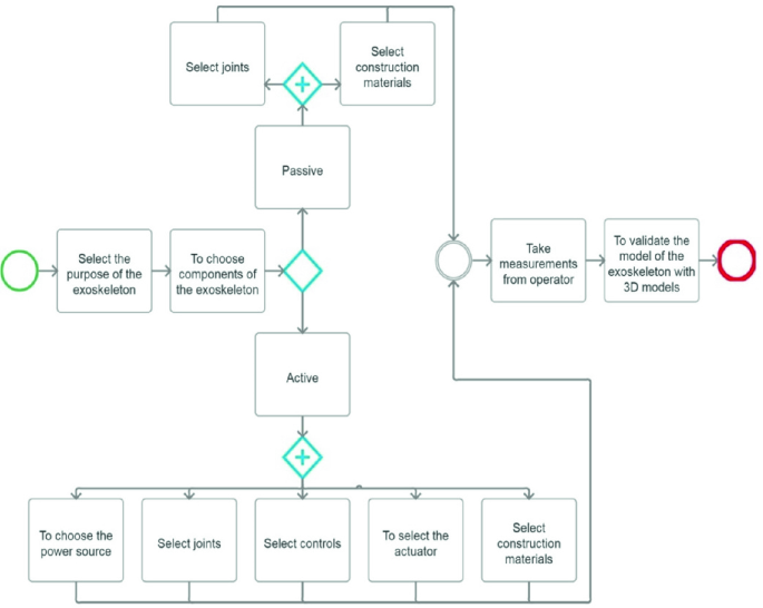
Exoskeleton design method

2.4 Designing a Synthesis Module
Patents [17, 20, 22, 25, 26] were found and analyzed to create parametric components of the assembly of the exoskeleton of the passive and active type. From the drawings of the patents selected parts. Developed models of parts, details are parameterized in the Autodesk Inventor. The general synthesis algorithm is presented in Fig. 4. The algorithm of the processing module is presented in Fig. 5.

(4) A general algorithm for the synthesis of the exoskeleton. (5) Diagram of the module processing the anthropometric parameters of the operator. (6) Algorithm for generating a parameterized assembly of the exoskeleton according to its type in the autodesk inventor system
Next, the module for generating a parameterized assembly based on its type in the Autodesk Inventor system was developed (Fig. 6). You need to use Inventor’s API to design a module for generating a parameterized assembly of an exoskeleton in Autodesk Inventor.
In order to integrate the operator’s anthropometric parameters processing module with the parameters of the exoskeleton assembly, a stand-alone EXE program is used, which runs on its own and connects to the Inventor. This type of program is usually used when there is a program that has its own interface and does not require the user to work interactively with Inventor [27, 28].
The parametrization subsystem is part of the exoskeleton design system and allows you to customize the exoskeleton model for a given size of a human operator, taking into account the anthropometric parameters of a person [29]. The subsystem allows reducing the time spent on inputting the parameters taken into the model.
To link the Inventor with the exoskeleton design subsystem, the Inventor API is used (Fig. 7).

Inventor API operation diagram
An API, or application programming interface, is a term used to describe the functionality of the Inventor graphical editor provided by the program.
Autodesk Inventor is a common CAD system, which means that it is not intended for any particular industry or is used to model only certain types of products. Having an API allows you to add Inventor-specific functionality that is specific to individual needs.
The Inventor API is implemented based on COM technology and provides various ways to access Inventor data using various types of add-in applications (Plug-in modules).
Components that provide API—Inventor and “Apprentice Server”. Inventor Data at the base represents Inventor data accessed by parts, assemblies, drawings.
Add-in (DLL), Standalone EXE, Add-in (DLL), VBA, Application represent programs that are written separately. When one field includes another field, it indicates that the included field is executed in the same process as the field that includes it.
For example, VBA runs in the same process as an Inventor. A program that runs in the same process runs much faster than a program that runs “out of process”.
Usually, choosing VBA, guided by the following advantages:
-
VBA is a programming environment that is accessible from within Inventor and is not required to purchase an additional programming language;
-
you can implement programs within the document for which processing they are designed. You can also save programs in separate files so that they can be used in various documents;
-
VBA runs in the same process as Inventor;
-
VBA has the same access to all features of the API as any of the other ways to access the API (with the exception of Add-Ins).
Standalone EXE is a program that runs independently and connects to the Inventor. This type of program is usually used when you have a program that uses Inventor but has its own interface and does not require the user to work with Inventor interactively. For example, the program can monitor new records that will be added to the database. When a new entry is created, the program launches Inventor, opens the desired document and prints it—all without any user interaction.
Apprentice (journeyman) server is a subset of Inventor that does not have a user interface and runs in one process with another application. The only way to interact with the Apprentice server is through its API. Apprentice server is much more efficient than using Inventor because, without a user interface, operations are performed faster. The Apprentice type library contains a limited set of objects supported by the Inventor type library. Apprentice provides access to the assembly structure, B-Rep geometry and render styles—read-only. Access to file links, attributes, and document properties—to read and write.
An Add-In is a special type of add-on application that automatically loads when Inventor is launched, has high performance and appears to the user as part of the Inventor. Inventor’s Add-In is a way to connect with Inventor and use its API. With the help of Add-In applications, you can create commands. The Add-In diagram is listed twice—as a DLL and as an EXE. DLL applications work in the same process as Inventor, EXE applications are convenient for debugging.
2.5 Interfaces of the Exoskeleton Design Subsystem
The exoskeleton design subsystem opens separately from Inventor, after launching the assembly of the exoskeleton on Inventor and mates with it using the Inventor API. A dialog box is launched in which you can begin work on taking measurements from a human operator. The subsystem interface consists of five tabs with the help of which the collected operator parameters are entered (Fig. 5).
The tabs “Belt”, “Hip”, “Drumstick”, “Stop” contain instructions with the image of individual human limbs with allocated places for taking the size of a person. Also, on the tabs are fields for entering data obtained from measuring a person. The minimum and maximum values are indicated, in the range of which the part of the assembly of the exoskeleton is built. If you enter a value less than the minimum or greater than the maximum, the program will automatically put the minimum or maximum value in the input field. There is a button on the tabs, which saves the entered data in the program and switches to the next tab.
Figure 8 shows the interface tab “Belt” of the exoskeleton design subsystem is responsible for parametrizing the details of the operator’s back “frame”.

Design subsystem interface “Belt” tab
User parameters of the part “Back frame” are changed using the design subsystem program:
-
Width of the part—S1—the parameter is changed by the user “1. Hip Girth”;
-
The part length—D1—is calculated automatically by the design subsystem D1 = S1/4;
-
The height of the part—H1—remains unchanged.
-
The height of the back of the part—HSpin—the parameter is changed by the user “2. Back height” (Fig. 9).
Fig. 9 
Two options for the model belt

The remaining parameters of the part are in the parameters of the Inventor, change automatically from the introduction of user parameters, see Fig. 10.

Two variants of the back frame model
Tab “Thigh” is designed to calculate the parameters of the skeleton of the thigh. Figure 11 shows the interface of the exoskeleton detail design subsystem, the parametrization of which, as well as in the previous tab, takes into account the entered parameters with size restrictions to maximum and minimum values.

Design subsystem interface “Belt” tab
The informational image shows in what places the hips should measure the human operator and how it will be done correctly. The tab shows the permissible maximum and minimum values.
The user parameters of the “Thigh carcass” part (Fig. 12) are changed using the design subsystem program:

Detail “The frame of the thigh” in the assembly and a separate part
-
Thigh-length—divided into two values due to the design features of the part, D1 and D2, therefore, when getting the value from the “1. Thigh Length”, the D2 parameter will receive the cell value divided by 3, and the D1 parameter will receive the D2 * 2 cell value;
-
The length of the location of the sensors is also divided into two values DKrep and DKrep2—and get the values according to the formula: DKrep and DKrep2 = (cell “2. Hip girth”/2 − 50)/2;
-
The width of the location of the sensors—DKDat—uses the cell “2. Hip Girth”/4;
The remaining parameters of the part are in the parameters of the Inventor, change automatically from the introduction of user parameters.
The “Shin” interface tab informs that the entered parameters will be sent to calculate the “Shin Frame” detail. This tab can be seen in Fig. 13.

Design subsystem interface “Shin” tab
The user parameters of the “Shank skeleton” part (Fig. 14) are changed using the design subsystem program:

Detail “The skeleton of the leg” in the assembly and a separate part
-
The length of the tibia is divided into two values due to the design feature of the part, D1 and D2, therefore, when retrieving the value from the “1. Shank length”, the D2 parameter will receive the cell value divided by 3, and the D1 parameter will receive the D2 * 2 cell value;
-
The length of the location of the sensors is also divided into two values DKrep and DKrep2—and get the values according to the formula: DKrep and DKrep2 = (cell “2. Girth of leg”/2 − 50)/2;
-
The width of the location of the sensors—DKDat—uses the cell “2. Girth of the leg”/4;
The remaining parameters of the part are in the parameters of the Inventor, change automatically from the introduction of user parameters.
The “Foot” tab informs you that the entered parameters will be sent to calculate the “Frame of the foot” part. This tab can be seen in Fig. 15.

Design subsystem interface “Foot” tab
The user parameters of the “Foot skeleton” part (Fig. 16) are changed using the design subsystem program:

Detail “The skeleton of the leg” in the assembly and a separate part
-
The length of the foot—DStop—indicates the values obtained from the cell “1. Foot length”;
-
The width of the foot—SStop—indicates the parameters stored in the cell “2. Foot width”;
-
Attachment height—DKrep—this parameter is calculated automatically using the formula DKrep = cell “1. Length of the foot”/2.7.
The final assembly of the exoskeleton of the lower extremities contains 42 components, 15 of which are typical elements of drives, fasteners, and hinges.
3 Conclusion
As a result of the work, the following tasks were carried out: a review of exoskeletons was conducted, a database was formed to select the type and type of exoskeleton, taking into account the requirements and restrictions of the operator to the exoskeleton; formed a parameterized library of exoskeleton elements and assembly of exoskeleton, taking into account the type; an algorithm for synthesizing the assembly of the exoskeleton of the upper and lower extremities of the operator, taking into account its anthropometric characteristics, requirements, and limitations to the exoskeleton, has been developed; A prototype for generating the assembly of an exoskeleton of human lower limbs was developed taking into account the anthropometric characteristics of the operator.
In the future, it is planned to replenish the parameterized libraries of elements of the exoskeleton and assembly of the exoskeleton of various types, to develop a prototype for generating the assembly of an exoskeleton suit and to develop a digital twin of the exoskeleton.
One of the key trends of the last couple of years is the “digital counterpart”.
The advantages of the digital twin are to provide a level of abstraction that will allow applications to interact with the device or devices in a consistent manner. The digital twin monitors the life cycle of the device and the data associated with the device. Digital twins allow you to simulate devices during development, integrate analytics, machine learning, etc.
Basic concept: monitoring of a physical object is carried out on the basis of a closed cycle of information exchange between it and its virtual model (thereby the digital counterpart).
The digital twin can be used as a starting point for a simulation model that may extrapolate how the system will work in the future. The degree and accuracy of these simulations can vary depending on the implementation of the simulation and the desired result.
For example, a CAD drawing package can be used to create a digital model, and then the process control system will use this model as the basis for the digital twin. This software can provide a connection between digital twin sensors and controls with those in the real world.
On the other hand, if the desired results are related to how strong the part will be inside the engine, then the relative level of detail should be greater.
The model used in the simulation may have the characteristics added so that physical modeling is possible. The model may include detailed information about the virtual materials used in the model, which, in turn, will allow the modeling software to replicate the response of the model during the simulation.
Models can have different goals, but they can also have general descriptions, such as information about dimensions, material attributes, etc. Many models can be used by several applications for different purposes, showing the status of the current system to simulate a device that has yet to be built [sixteen].
Since the digital twin will simplify the task of testing, allowing for quick correction and detection of anomalies, it was decided to further design the digital twin and develop recommendations for optimizing the operating mode and maintenance of the exoskeleton.
References
Kelechava, B.: Powered exoskeletons [Electronic resource]. https://blog.ansi.org/2016/06/powered-exoskeletons/#gref (appeal date: 12.26.2017)
Exoskeleton robots are on the verge of exponential market growth [Electronic resource]. Access mode: https://exoskeletonreport.com/what-is-an-exoskeleton/
A survey on static modeling of miniaturized pneumatic artificial muscles with new model and experimental results [Electronic resource]. Access mode: https://www.researchgate.net/publication/328209567_A_Survey_on_Static_Modeling_of_Miniaturized_Pneumatic_Artificial_Muscles_With_New_Model_and_Experimental_Results
Sobia, A.: What is an exoskeleton? Exoskeleton report. Access mode: http://exoskeletonreport.com/what-is-an-exoskeleton/ (access date: 26.12.2017)
Kazerooni, H.: Exoskeletons for human performance augmentation. In: Siciliano, B., Khatib, O. (eds.) Springer Handbook of Robotics. Springer, Berlin (2008)
Lee, H., Yu, S., Lee, S., Han, J., Han, C.: Development of human-robot interfacing method for assistive wearable robot of the human upper extremities. In: Proceedings of the SICE Annual Conference, pp. 1755–1760 (2008)
Daly, J.J., Hrovat, K., Pundik, S., Sunshine, J., Yue, G.: fMRI methods for proximal upper limb joint motor testing and identification of undesired mirror movement after stroke. J. Neurosci. Methods 175(1), 133–142 (2008)
Frumento, C., Messier, E., Montero, V.: The history and future of rehabilitation robotics. Access mode: https://web.wpi.edu/Pubs/E-project/Available/E-project-031010–112312/unrestricted/HRRIQP_Final.pdf (2010)
A novel gait-based synthesis procedure for the design of 4-bar exoskeleton with natural trajectories. Access mode: https://www.researchgate.net/publication/321206172_A_novel_gait-based_synthesis_procedure_for_the_design_of_4-bar_exoskeleton_with_natural_trajectories
Meng, Q.: Research on size synthesis optimization design of a bionic exoskeleton for index finger rehabilitation. Adv. Mater. Res. 945–949, 1447–1450 (2014)
Menga, G., Ghirardi, M.: Lower limb exoskeleton for rehabilitation with improved postural equilibrium. Robotics 7(2), 28 (2018)
Song, Z., Tian, C., Dai, J.-S.: Mechanism design and analysis of a proposed wheelchair-exoskeleton hybrid robot for assisting human movement. Mech. Sci. 10(1), 11–24 (2019). https://doi.org/10.5194/ms-10-11-2019
Exoskeleton robots are on the verge of exponential market growth [Electronic resource]. Access mode: https://www.robotics.org/service-robots/exoskeleton-robots
Chen, B., Ma, H., Qin, L.-Y, Gao, F., Chan, K.-M, Law, S.-W., Qin, L., Liao, W-H.: Recent developments and challenges of lower extremity exoskeletons. J. Orthop. Transl. 5 (2015). https://doi.org/10.1016/j.jot.2015.09.007
Exo robotics. Access mode: http://exo-robotics.ru/ (access date: 26.12.2017)
A review of exoskeleton-type systems and their key technologies. Access mode: https://www.academia.edu/6275563/A_review_of_exoskeleton-type_systems_and_their_key_technologies
Types and classifications of exoskeletons. Access mode: https://exoskeletonreport.com/2015/08/types-and-classifications-of-exoskeletons/
Robotic exoskeleton: for a better quality of life [Electronic resource]. Access mode: https://www.maxonmotor.com/maxon/view/application/Robotic-exoskeleton-For-a-better-quality-of-life
Harvard scientists design soft robotic exoskeleton to reduce fatigue and injuries [Electronic resource]. Access mode: https://www.extremetech.com/extreme/190025-harvard-scientists-design-soft-robotic-exoskeleton-to-reduce-fatigue-and-injuries
Chernikova, L., Suponeva, N., Klochkov, A., Khizhnikova, A., Lyukmanov, R., Gnedovskaya, E., Yankevich, D., Piradov, M.: Robotic and mechanotherapeutic technology to restore the functions of the upper limbs: prospects for development (review). Sovremennye tehnologii v medicine 8, 222–230 (2016). https://doi.org/10.17691/stm2016.8.4.27
Servo control facts. Access mode: http://www.baldor.com/pdf/manuals/1205–394.pdf (access date: 27.04.2018)
Pallas-Areny, R., Webster, J.: Sensors and Signal Conditioning. SERBIULA (Sistema Librum 2.0) (2019)
A great combination: pneumatic actuator, pneumatic timer, pneumatic valves, and pneumatic indicators. Access mode: http://www.ekci.com/a-great-combination-pneumatic-actuator-timer-valves-and-indicators-ezp-69.html (access date 14.04.2018)
Gopura, R., Kiguchi, K.: Mechanical designs of active upper-limb exoskeleton robots: state-of-the-art and design difficulties, pp. 178–187. https://doi.org/10.1109/icorr.2009.5209630. Access mode: https://www.researchgate.net/publication/224580506_Mechanical_designs_of_active_upper-limb_exoskeleton_robots_State-of-the-art_and_design_difficulties (2009)
Rehmat, N., Zuo, J., Meng, W.: Int. J. Intell. Robot Appl. 2, 283 (2018). https://doi.org/10.1007/s41315-018-0064-8
Zang, D.-T.: Adaptive electric drive control exoskeleton [Electronic resource]. Access mode: https://etu.ru/assets/files/nauka/dissertacii/2017/Do-Than-Zang/Dissertaciya-_Do-Than-Zang.pdf
Nacy, S., Hussein, N., Abdallh, M.M.: Review of lower limb exoskeletons [Electronic resource]. Access mode: https://www.researchgate.net/publication/313877170_A_Review_of_Lower_Limb_Exoskeletons
Design and motion control of a lower limb robotic exoskeleton [Electronic resource]. Access mode: https://www.intechopen.com/books/design-control-and-applications-of-mechatronic-systems-in-engineering/design-and-motion-control-of-a-lower-limb-robotic-exoskeleton
Titov, A., Markov, A., Skorikov, A., Tarasov, P., Andreev A.E.: Autonomous locomotion and navigation of anthropomorphic robot. In: Communications in Computer and Information Science, CIT&DS 2017, vol. 754, pp. 242–255 (2017)
Acknowledgements
The reported study was funded by RFBR according to the research project # 19-07-01200 and technically supported by the Project Laboratory of Cyber-Physical systems of Volgograd State Technical University.
Author information
Authors and Affiliations
Corresponding author
Editor information
Editors and Affiliations
Rights and permissions
Copyright information
© 2020 Springer Nature Switzerland AG
About this chapter

Cite this chapter
Matokhina, A., Dragunov, S., Popova, S., Kravets, A.G. (2020). Method of the Exoskeleton Assembly Synthesis on the Base of Anthropometric Characteristics Analysis. In: Kravets, A., Bolshakov, A., Shcherbakov, M. (eds) Cyber-Physical Systems: Advances in Design & Modelling. Studies in Systems, Decision and Control, vol 259. Springer, Cham. https://doi.org/10.1007/978-3-030-32579-4_3
Download citation
DOI: https://doi.org/10.1007/978-3-030-32579-4_3
Published:
Publisher Name: Springer, Cham
Print ISBN: 978-3-030-32578-7
Online ISBN: 978-3-030-32579-4
eBook Packages: EngineeringEngineering (R0)