
Abstract
IDE covers product planning, marketing, industrial design, development and engineering design, process planning, prototype and sample manufacturing as well as testing up to production release (Fig. 2.10). Process integration and organization integration include all measures necessary to describe, consolidate and improve business and development processes and organization forms.
Access provided by Autonomous University of Puebla. Download chapter PDF
Sándor Vajna
IDE covers product planning, marketing, industrial design, development and engineering design, process planning, prototype and sample manufacturing as well as testing up to production release (Fig. 2.10). Process integration and organization integration include all measures necessary to describe, consolidate and improve business and development processes and organization forms. These concern both the structure of an organization and the way in which and under which conditions the activities for processing tasks are carried out. In IDE, task processing and organization must both be flexible in order to be able to react appropriately to changes of requirements and environments. This is achieved in IDE by making structures and processes, respectively, increasingly dynamic.
Figure 15.1 shows the interaction of product, organization and process as well as the resulting mutual conditions and dependencies

Interaction and coupling of product, organization and process (grey-shaded areas on the main diagonal: definition of the respective object)
-
The product as the result of human skill and action requires a basic process structure for its creation. At the same time, an appropriately adapted organization must be available for its creation.
-
The organization as the purposeful cohesion of a structure of people and units provides the structural organization for the creation of the product and the process organization for carrying out the processes required for this.
-
The process as a guideline for working on a task can only function in appropriately adapted organizations in order to enable the creation of a product.
Product, organization and process form a stable and indissoluble network in which the relationships of the participants are clearly defined, which must be observed in terms of organizational and process integration. While the variety of products was presented in Sect. 2.3, this chapter deals with the processes and projects required for the development of a product and possible forms of organization for IDE. A distinction is made between the structural organization and the process organization.
Activities in IDE are neither predictable nor fully reproducible due to their creative part and the high probability of changes. Due to unclear processes and information flows as well as changes in requirements and environment, it is often difficult to track current project progress. Moreover, in this dynamic environment, it is hardly possible to fully control and document the goals, times, resources and costs of a project. This means that activities in IDE differ fundamentally from those in production, sales, administration and controlling, Fig. 15.2.

Differences between activities in manufacturing, controlling, administration and IDE
After release for production, the downstream areas can only work with fully described objects as well as with fully described processes. Otherwise, for example, production cannot produce products of the same quality regardless of their quantities, cannot create comparable financial balances in company accounting (to which controlling department also belongs), and, in administration, cannot assure comparable procedures for payroll accounting. Because objects and activities are complete and reproducible, a process control is usually sufficient.
Activities in IDE are usually complex and dynamic, not only because both the creative development and realization of surprising innovations do not follow a strictly prescribed path, but also because many projects are carried out by different employees with growing ranges of tasks and different qualifications, predominantly simultaneously and often at different locations (e.g. in development partnerships in the automotive industry). IDE often contains complex configurations of activities in which some are serial and others are parallel. In industrial practice, it is also difficult to monitor current project progress due to unclear processes and information flows.
When placing an order, customers often do not know all requirements for the desired product (as a lot of them only arise during development) or change their requirements during on-going development on the basis of new knowledge that has arisenFootnote 1 whereby it is expected as a matter of course that, despite these changes, once agreed requirements, time and cost frames are kept without being adjusted accordingly.
This chapter describes possible measures for improving development processes, different forms of structural organizations and process organizations, and dynamic navigation. The IDE procedure model based on these is described in Chap. 16.
15.1 Process Improvement
In terms of activities, IDE distinguishes between processesFootnote 2, workflows and projects.
-
An (organizational) process is a concept, a specification or a rule for processing a task in the form of a structure of interrelated activities (process steps) or subprocesses in logical sequences. Activities or subprocesses are not limited in length and duration. Links between activities and subprocesses are not rigid; they can be active or inactive. Accordingly, the management of processes does not serve their control but their design with the aim of simplifying and improving them.
-
A workflow is a fixed, rigid sequence of activities and subprocesses that cannot be changed for reasons of comparability and reproducibility or due to legal regulations (e.g. release process or change process in IDE, but also every organizational process in production, administration and controlling).
-
A project is characterized by a concrete order with unique individual conditions. It has a defined start (project start) and a defined end (delivery date). A project comprises all processes and/or workflows for creating and documenting an individual product described by actual (and individual) requirements, boundary, initial and environmental conditions for a specific purpose and in a specific configuration (scope of services). The project is subject to limitations in the number of agents, the tools and resources available, and budgeting. For the successful execution of a project, project management includes various management tasks, organization, techniques and means [DIN-69901].
The transition from a process to a project takes place through a specific internal or external order with a defined scope of services and fixed conditions regarding budget, resources and delivery date.
The aim of process improvement is to increase efficiency through faster processing, the most economical use of resources and the avoidance of processing errors. The aim is to enable better cooperation through integration, appropriate use of resources and parallel procedures, thus leaving behind a rather work-sharing organization with predominantly fragmented processes.
There are numerous methods for process improvement. The so-called direct methods redesign the process structure in advance, such as business process reengineering [StVa-1996], indirect methods record and evaluate the results of processing in order to derive changes, such as Six Sigma (a method of quality management and process optimization [DaHa-2009]) and the continuous improvement process [EhMe-2013].
The improvement of processes can take place in several stages. In doing so, the basic structure of the process organization (Sect. 15.3) is not called into question.
-
The required qualification for each activity is determined and compared with the actual qualification profiles of the employees. Usually, employees with appropriate qualifications are deployed for processing. However, if employees with higher qualifications are deployed, processing is more efficient and processing times are shortened.
-
Instead of individual procedures, procedure patterns are used that have proven themselves in the company or with external parties (the so-called best practices).
-
Sophisticated methods, aids or tools are used more than before. On the one hand, this improves the quality of work. On the other hand, either the processing time can be reduced or more results can be achieved in the same time.
The results of these measures are shown in Fig. 15.3.

Results of skills improvement, use of best practices and higher value methods, means and tools
-
Activities with which comparable tasks are processed are complemented and linked to subprocesses. This serves not only a “mild” standardization of procedures, but also the elimination of interfaces between individual activities and the tools used for support. This contributes to the realization of error-free and interdisciplinary working methods.
-
Activities can, if the processing logic allows it, be moved into different sequences and arranged differently.
-
Activities are parallelized according to the procedures of Simultaneous Engineering (SE) and of Concurrent Engineering (CE), Fig. 15.4. In SE, different (and originally consecutive) activities are overlapped and executed in parallel (in product development, e.g. development, design and process planning). In CE, a single task is divided among several persons (step TS), who process it in parallel. Therefore, the definition of physically and logically delimited areas (the so-called design spaces) with clear interfaces is necessary. The results of the activities are merged and compared at the end of processing and thus consolidated (step MC). For SE and CE, the most important criterion for parallelization is the question when the results of the previously started work step are so stable that the statistical probability of a change and the associated change costs are lower than the costs caused by working and delivering too late [VWZH-2018].
Fig. 15.4 
Possibilities of parallel processing (SE = Simultaneous Engineering, CE = Concurrent Engineering, TS = Task sharing, Z & A = Merging and alignment)
-
As further measures, where technically and organizationally reasonable, activities can be broken down into smaller units (such as CE) and their arrangement and their processing sequence can be changed. This sequence can be further improved by changing the process topology accordingly.

The measures described here are mainly of organizational nature. No great effort is required to implement them. Conversely, this means that if the result does not meet the expectations, it is also possible to restore the original state with little effort so that the economic risk of these process improvements is low.
15.2 Structural Organization
A basic distinction is made between the structural organization and the process organization [Burc-2001]:
-
The structural organization regulates the distribution of the tasks of a socio-technical system (enterprise, authority, association or other systems) between different organizational units as well as the relationships and cooperations of these units. The organization can be structured in different ways, for example in permanent positions and departments or in temporary teams that are only formed to process a task and then break up again. Management, staff and communication relations serve to regulate cooperation [Groc-1983]. The organizational plan provides the structures for the implementation of targets and company goals as well as for the provision of services with content over time, time, composition and scope.
-
The process organization describes the spatial and temporal sequence of the interaction of employees, resources and work objects or information and the associated activities in the fulfilment of work tasks, taking into account factual-logical, personal and spatial-time aspects. The process organization is dealt with in detail in Sect. 15.3.
The structural organization is divided into the line in which the company’s value is created, and the staff that supports the line and can thus only indirectly contribute to value creation.
-
The line organization includes those areas of the product life cycle that are located within the company or are influenced by the company.
-
The staff organization includes the central areas for the entire company or within a line (e.g. personnel area, purchasing, payroll accounting).
The structural organization can be function-oriented, a matrix organization, a project organization or a mixture of these.
A task can be processed either by a workgroup or by a team. A workgroup is
-
a group of employees who work together in an organizational unit on a permanent basis, either on a factual or process-related basis. The number of group members is unlimited.
-
usually hierarchical and function-oriented and remains togetherFootnote 3 for a very long time. It mainly works on routine tasks, whereby work and structuring can be oriented to functions, assemblies, product properties or phases.
The exchange of information or the coordination of procedures with other workgroups usually takes place via the superior unit. Within the workgroup, information exchange and coordination primarily serve to make decisions that support an individual member in providing performance within his or her own area of responsibility. In the workgroup, individual performance is rated higher than the overall result, especially as the performance evaluation of the employees is carried out individually.
Teamwork is discussed in detail in Sect. 15.6.
15.2.1 Function-Oriented Structural Organization
In a function-oriented structural organization, there is a clearly arranged hierarchical structure which is divided into functional areas of competence and responsibility (division of tasks) and in which the relationships between the individual organization units are built up in the form 1:n. Units are often isolated from each other due to the division of tasks. They have a specific profile of skills and abilities to solve limited tasks, but do not cover the overall solution. Skills and abilities are usually execution-oriented; i.e., they provide the same functions for different tasks or product groups. For example, a unit can be the management, a department, a group of employees or a single employee. Other units can be subordinate to one unit. Superior units are authorized to give instructions to the subordinate units.
In such an organization, work tasks must be clearly described and structured. Thus, fixed procedures are used in which a high degree of detail already exists for task processing and only limited product or process adjustments have to be made. Therefore, the function-oriented process organization has a low ability to react to changing requirements. Due to its lack of dynamism, it is usually unable to react flexibly to changes; instead, the tasks have to be adapted to the rigid hierarchical structure.
Figure 15.5 shows an example of a structure divided into the specialist areas of industrial design, engineering design and process planning. For each subordinate unit, the task is divided into smaller and smaller parts. Each unit exclusively fulfils its own task. The results are combined and passed on via the respective upstream units.

Function-oriented organization
Since units often operate independently of each other, the know-how of one unit is difficult to access by the other units. This is why there is a risk of redundant developments without timely comparison of information and knowledge. Cross-functional goals are difficult to realize, as integration into hierarchical structures is generally difficult to achieve.
Information and communication flows run according to the structural organization from the superior to the subordinate unit (top-down) or vice versa (bottom-up), but usually not between units at the same hierarchy level (peer-to-peer). As a result, many interfaces (and idle times) are created between the units during the job run, by what the individual activities become more difficult to control and cumbersome decision-making processes can occur [Lang-1998].
This form of organization is very well suited for routine tasks in which the results of a task are passed on between the units by “pushing” them (push: Obligation to hand over the completed results to the successive unit; Sect. 15.2, see also Fig. 1.14). Processing is serial and static, since these are recurring activities.
15.2.2 Matrix Organization
The matrix organization results from the combination of two (planar matrix) or three function-oriented organizations (spatial matrix), Fig. 15.6. Thus, a unit at an intersection point of the matrix can be subject to several equally ranked positions with authority to give directives. For example, in the flat matrix, unit B1 reports to both the head of the design department and the head of product group 1. In the case of the spatial matrix, a further specialist area with authority to issue directives is added (In Fig. 15.6, these are the managers of the countries in which the product is distributed. It often happens that different versions of the product exist for each country (e.g. left-hand and right-hand drive vehicles, depending on the type of traffic).

Matrix organization (left: planar matrix with two responsibilities, right: spatial matrix with three responsibilities per unit)
Within the matrix organization, the units at the intersections can be not only the groups mentioned in Sect. 15.2.1, but also may again forms of organization, for example project organizations.
At the intersections, however, an intensive flow of information and communication can also occur, combined with a high level of know-how transfer. Certainly, there is also competition in the areas of responsibility and the decisions associated with them, so that in the worst case scenario there will be a mutual blockade. For this reason, as in a function-oriented organizations, a single unit in such a matrix is usually subordinated directly only to a single management function (disciplinary or personnel directive authority), while the other management functions have technical directive authority (“dotted line”), with which they can influence the development of a product, for example.
15.2.3 Project Organization
In project organization there are no permanent subordinations and no fixed structures. Instead, the units required for processing a project are separated from the individual departments and brought together to form an independent organizational unit for the duration of the processing of the project, the project team. Project tasks are handled in parallel and dynamically, with the project members working with both “pushing” the results and “pulling” the results (pull: Obligation to collect the completed results from the preceding unit) as required. In this way, interdisciplinary cooperation is achieved, which contributes to a high degree of identification of the project participants with the project. The project is the responsibility of a project manager, who ideally reports directly to the executive board, Fig. 15.7. After completion of the project, the project members return to their original structures.

General project organization
The project manager flexibly coordinates and controls the work tasks of his team. He ensures that each project member has their own workspace, which should provide sufficient overlap with the other workspaces to ensure communication within the project team.
For very small or very short-lived projects, employees from different departments can form a project team, but remain under the disciplinary supervision of their respective superiors. In this type of project, the project team coordinates itself, Fig. 15.8.

Different project organizations (dark grey elements: members of a project with full-time project manager, light grey background: members of a self-coordinating project)
There is currently no company that is completely organized in projects. Rather, hierarchically structured functional areas exist on an equal footing with project teams led by project managers. If the rules of cooperation are not clear, this can lead to non-ambiguous information flows and competence problems.
Project organization is best suited for IDE with its temporary teams that only work together for the duration of a project, because it enables a holistic view on and the integration of all processes with the least organizational effort. This results in both departmental integration in IDE (Chap. 14) and the integration of operational processes, technologies and information technologies as well as the implementation of cross-departmental, interdisciplinary cooperation with flat hierarchical structures, short decision paths and an increased flow of information and communication. In order to facilitate the associated transfer of know-how between the individual projects, it is helpful if the project managers themselves can work together in a team of project managers under the direction of the executive board.
In an IDE team, the project manager is more of a moderator and a coach than a “classic” project manager, because the proportion of self-organization in the team in IDE is high right from the beginning and it increases as the project progresses. This results in transparent project responsibility in which all team members are involved. This enables know-how to be acquired together, combined and made available to all project members. If required, additional organizational units can be formed with individual project members within the project team. Such units are used to work on subject-related goals and content.
15.2.4 Networked Organization
The organizational forms presented so far in product development must be dynamized, because IDE requires sufficient flexibility in the composition of the team as well as in reacting to changed external and internal requirements and changed environments.
Dynamic forms of organization are characterized by flexibility, reactivity and a process-flow-oriented liveliness or agility of processes. In contrast to function-oriented organization forms with structural and process organizations with the inherent rigidly structured, hierarchically organized structures, dynamic project-oriented structural organizations use open, flexible and customer-oriented organization forms. The hierarchy levels are less, decision-making responsibilities in the operative areas are extended and work tasks are executed interdisciplinarily across areas and functions [Burc-2001].
Dynamic forms of organization can be mapped in the form of network structures. In general, a network consists of nodes that are connected to each other via edges. With regard to an organizational form, the nodes correspond to the units discussed in the previous sections and the edges represent the connections between the units, whereby these connections can represent organizational dependencies or information and communication flows, for exampleFootnote 4.
The structure of a networked organization results from both type and scope of the units involved in the network, as well as from the type of relationships between them [Vier-1996]. In addition to the function-oriented structure, a distinction is made between internal, dynamic and stable networks, Fig. 15.9.

Composition and properties of different network types
-
Function-oriented structures were discussed in Sect. 15.2.1.
-
Internal networks exist within a company in a fixed and equal network cohesion without redundancies. There are little or no external contacts. A separate unit coordinates them. Each network participant has its own exclusive task. The stability of this type of network is low, because in the event of a network member’s failure, the respective task is no longer processed and it is often difficult to replace a network member. The organizational flexibility is correspondingly low.
-
Stable networks are the result of permanent and predominantly long-term connections between a leading company and external companies (partner or supplier). The resources of the external companies complement the resource pool of the leading company (even if there may be deliberate redundancies). Core competencies and entrepreneurial risk are mainly located at the leading company. The coordination effort is higher because, in addition to the internal coordination, the integration of external parties must be taken into account. The flexibility of a stable network is very high.
-
Dynamic networks are made up of loose but equal connections between companies that are independent of each other and thus do without redundancies. A common form is the development partnershipFootnote 5. When defining common goals and tasks, different company interests must be reconciled in the sense of equal cooperation. Since each individual company has its own structures, some of which have different decision paths, it is less controllable than an internal network and often requires more effort to coordinate the collaboration. In return, organizational flexibility increases.
The development of a larger pool of know-how in the network is advantageous, which can release higher innovation potentials, for example. With stable and dynamic networks, this also entails the risk of an undesired transfer of information to other companies and a resulting outflow of know-how.
As it has already been stated, project organization is the most suitable form of task management for IDE. This is now applied to a network structure to enable and support dynamic and flexible approaches that are product- or process-oriented and not function-oriented. This includes the close and interdisciplinary cooperation of all project participants, the development of teamwork structures, and a high degree of transparency of processes and decision paths as well as unimpeded information and communication flows.
The flexible form of a network structure is an ideal organizational form for IDE project work. A network structure supports any desired working constellation of units, such as serial, parallel, feedback or mixed forms. Dynamic activities, such as changes in forms of cooperation and/or partners during a project, are also supported. The basis of this network structure is the mesh network, in which basically any unit can be connected to any other. A mesh network allows to represent flexibly possible as well as actually realized and currently used connections and relationships.
In such a network the structures are flat and permeable with short and direct communication and information paths. Each unit can work largely autonomously so that a clear division of tasks and clear responsibilities become possible. This accelerates the coordination of work processes as well as decision-making and solution finding. The flexible design of the forms of cooperation and communication enables the involvement of all participants in the development process, promotes interdisciplinary work, increases the ability to react to external influences and supports decision-making [Burc-2001].
Based on Fig. 15.7 the resulting IDE network structure shown in Fig. 15.10, in which essentially three types of units are represented.

IDE network structure (units in IDE core team: shaded circles, units in the extended team: dark grey circles, units in the external team: empty circles. grey area: department) [Burc-2001]
-
The IDE core team works on the core tasks of the project. It acts as the central coordination office together with other teams. It consists of representatives of the departments required for this work and it remains in duty throughout the entire project duration.
-
The extended team is made up of specialists from the company who are needed at certain times or at work sections, but who do not carry out the actual project work. It can happen that one person has to be integrated into several extended teams.
-
If experts are needed from customers, partners, suppliers and other external parties, they are integrated into external teams.
Interdisciplinary and interdepartmental coordination institutions control and manage this network structure. Such an institution can be, for example, a superior project manager (Fig. 15.8) or a department head.
15.3 Process Organization Approaches
The process organization can be divided into the processing of routine tasks and of projects. Principle of operations may be either the “push” (obligation to deliver the completed results to the successive unit(s)) or the “pull” principle (obligation to collect the completed results from the preceding unit(s)). From a structural point of view it can be structured into serial or parallel processing and from a reaction type point of view into static and dynamic processing, Fig. 15.11.

Elements of the process organization
The two types of activity are routine tasks or projects:
-
Routine tasks are recurring activities that hardly (or no longer) require creative work, but can always be carried out with comparable results using experience that was gained once.
-
The characteristics of a project with individual objectives as well as fixed deadlines and resources lead to a one-time (and often also first-time) application of certain processes, procedures, tools and aids. This requires an individual approach to a task each time, even if existing experience and solution patterns can be used for subareas of the project.
When working with other units, a distinction is made between the push principle and the pull principle:
-
With a push principle a unit processes a task and must pass on its partial and final results to the next unit, which then processes the task further.
-
With the pull principle the downstream unit must obtain partial and final results from the upstream unit. It can then begin processing.
The workflow can be structured into sequentially, parallel or mixed forms:
-
In sequential processing, the individual steps are processed one after the other. A new step can only be started as soon as the previous one has been completed.
-
Simultaneous Engineering (SE) or Concurrent Engineering (CE) can be used for different types of parallel processing (see Sect. 15.1).
The processing procedure can be static or dynamic:
-
The static procedure triggers a process flow that cannot be changed during processing (workflowFootnote 6). External changes (regardless from whom or from where they originate) are not taken into account.
-
The dynamic approach allows you to react appropriately to changes in requirements or the environment at any time in order to meet deadlines and budgets.
This results in the following preferences for IDE:
-
Since there are almost no routine tasks in IDE, only the processing in the form of projects is possible. Integration of the individual areas involved in the product life cycle can only be achieved in the project organization.
-
Team members work with the push or the pull principle, as required.
-
In the projects, people work in parallel as a team, whenever possible. Which of the parallelization forms is applied depends on the extent of the respective task (then preferably CE) and whether it is time-critical (then preferably SE). If a task is extensive and time-critical, the mixed form shown in Fig. 15.4 is used (but see also Fig. 15.7).
-
Static procedures are more likely to be found in the areas downstream of IDE (see also Fig. 15.2). In IDE itself, all procedures are dynamic.
There are numerous concepts for designing and managing the process organization, of which typical representatives are presented. These are the Stage-Gate process, the milestone-based project processing, two approaches of Agile Development (Scrum and Extreme Programming), Lean Product Development, and, as a transition to dynamic navigation (Sect. 15.7), Dynamic Product Development, which has already been presented in Sect. 1.4 but is described here from an organizational process perspective, as well as an approach to recognize and use recurring patterns in the problem-solving space of product development.
15.3.1 Stage-Gate Process
The stage-gate process by Cooper [Coop-2002] distinguishes between a work phase (stage) and decisions to make at a certain time (gate). Stages and gates are defined with regard to their content and consequences, Fig. 15.12.

Stage gate process (white arrows with text: stages, grey rhombuses: gates) [Coop-2002]
-
Stages are preliminary studies in the basic plan, detailed investigations and preparation of the business plan, development work up to the prototype, test and evaluation of the results to date, start of production or market launch as well as the final evaluation (review). It is possible to add further stages at the beginning of the project.
-
Gates are at the beginning of the project (project estimation: decision whether the project should be started at all) and then after each stage. These decisions are defined in terms of content and time. Before passing to the next gate, the results of the respective preceding stage are evaluated by all groups involved in the project according to previously defined criteria. This can lead to rectification within the current stage. A gate can either be passed (then the next stage will begin) or not passed (then the project will be aborted). A gate cannot be passed through twice.
The stage-gate process is a sequential and rigid approach, which (like traditional Engineering design methods) assumes that the requirements formulated at the beginning will remain fixed during the course of the project and that the environment will not change either [Otto-2013]. This model is therefore not suitable for structuring project work in IDE.
15.3.2 Milestones
Milestones serve for structuring and thus for a better overview of the project process. On the one hand, they describe intermediate results relevant for the project process [DIN-69901], which can be achieved by using pre-defined (predetermined) resources (e.g. the availability of suitably qualified employees, machine capacities). During their scheduling, dependency and priority relationships are also established between them and milestones that have already been completed and to subsequent milestones. If a milestone cannot be reached at the time specified for it, the employees involved in a project must run through the relevant work packages again (also across working phases) to fulfil the milestone. Existing results are revised until the results are compatible with the milestone conditions or the assigned requirements of the milestone have been changed accordingly.
Milestones, on the other hand, are timely determined targets at which previously defined results must be presented. They provide a snapshot of all current activities of a project and evaluate their results. After negative evaluation, milestones can be repeated or offset.
The milestones include, for example
-
Project start (the so-called kick-off) and project end,
-
the respective logical end (completion of a project phase and transfer of the results to the next project phase) or financially conditioned end of a project phase (release of funds for the next phases takes place depending on the results achieved so far) and
-
the “point of no return”, i.e. the point in time from which it is no longer possible to terminate the project without significant damage (technical, economic, political, etc.).
Most of the milestones used in IDE refer to the complete fulfilment of particular work packages. They are therefore defined in terms of content and not in terms of time and they are of a dynamic nature. This gives the employees involved the time they need and helps them to manage the project in a result-oriented manner. These milestones are intended to coordinate the development work.
Decisions that could jeopardize the continuation of the project are taken, where applicable, in timed milestonesFootnote 7. In industrial practice, such milestones are preferred because they enable the client (or the higher management of the development company) to call up the current project status at any time and to keep an open decision on the continuation of the project. Due to this permanent possibility of project termination (often for cost reasons), work results have to be generated continuously so that they can be verified. Extensive process parallelization with work results that are open over a longer period of time is therefore only possible to a limited extent.
In summary, the term “milestone” can be defined and understood in very different ways (e.g. in terms of time, content, repeatability, rigidity). The most common application is fixed in terms of content and time and is therefore rigid and inflexible.
It therefore makes sense for IDE to delimit certain development phases no longer by milestones but by various events defined in terms of content (project status queries and decision points in time) in order to maintain the flexibility and dynamics of the development processes, especially with regard to the processing time of the individual phases.
An IDE process is structured in such a way that project management can react as easily as possible to problems and changes in requirements within the entire project. The properties of the different elements of the process should therefore be exploited as much as possible in order to save as much processing time as possible. The main instruments are the phase endings [Neut-2010]:
-
Project status query (PSA): Since PSA is defined in terms of content rather than of time, one has the option of bringing forward or postponing a roughly planned phase end. In this way, bottlenecks can be compensated or time buffers can be created.
-
Decision point in time (DPT): The phase end by a DPT is basically not always to be regarded as fixed. Rather, it is to be seen as partially dynamic, i.e. it is quite possible to bring forward the DPT in the event of early provision of results. Only the time after the specified decision date cannot be used, as otherwise the timely completion of the project cannot be guaranteed.
15.3.3 Agile Development
Generally seen, AgileFootnote 8 Development refers to a group of development methods based on iterative development, where requirements and solutions evolve through collaboration within self-organizing teams. The Agile development methods have their origins and roots in software development, from practice rather than from academia (e.g. [SuNa-2018]). The Agile view is spreading rapidly also to non-technical areas. Agile development (AD) is an umbrella term for a set of frameworks and practices based on the values and principles expressed in the Agile Manifesto [Agil-2019].
Agile methods all stress the use of autonomous self-organizing teams (see also Sect. 15.6). The term self-organizing team means “individuals [that] manage their own workload, shift work among themselves based on need and best fit and participate in team decision making.” The most widely adopted agile methods are Scrum and Extreme Programming (XP) (e.g. [HoSG-2018, PHSA-2008]). Scrum is becoming increasingly used for a lot of development tasks (e.g. [SAGS-2019, LiFu-2018]). While Scrum mainly covers project management, XP focuses on developmental practices. Both methods will be discussed further down.
15.3.3.1 Agile Foundational Values and Supporting Principles
Principles and philosophy of agile development are described in the Agile Manifesto from 2001, which comprises four foundational values and twelve supporting principles [Agil-2019]. The four Agile foundational values tell that
-
1.
Individuals and Interactions Over Processes and Tools
Valuing people more highly than processes or tools is easy to understand because it is the people who respond to business needs and drive the development process. If the process or the tools drive development, the team is less responsive to change and less likely to meet customer needs. Communication is an example of the difference between valuing individuals versus process. In the case of individuals, communication is fluid and happens when a need arises. In the case of process, communication is scheduled and requires specific content.
-
2.
Working Product Over Comprehensive Documentation
Historically, enormous amounts of time were spent on documenting the product for development and ultimate delivery. Technical specifications, technical requirements, technical prospectus, interface design documents, test plans, documentation plans, and approvals required for each are examples of this. The list was extensive and was a cause for the long delays in development. Agile development does not eliminate documentation, but it streamlines it in a form that gives the developer what is needed to do the work without getting bogged down in minutiae. Agile documents require user stories, which are sufficient e.g. for a software developer to begin the task of building a new function. The Agile Manifesto values documentation, but it values working on a working product more.
-
3.
Customer Collaboration Over Contract Negotiation
Negotiation is the period when the customer and the product manager work out the details of a delivery, with points along the way where the details may be renegotiated. With development models such as the Waterfall model (e.g. [Wien-2014]), customers negotiate the requirements for the product, often in great detail, prior to the start of any work. This means that the customer is involved in the process of development before development begins and after it is completed, but not during the process. Collaboration is a different creature entirely. The Agile Manifesto describes a customer who is engaged and collaborates throughout the development process. This makes it easier for development to meet the needs of the customer. Agile methods may include the customer at intervals for periodic demos, but a project could just as easily have an end-user as a daily part of the team and attending all meetings, ensuring the product meets the business needs of the customer.
-
4.
Responding to Change Over Following a Plan
Traditional development regards change as an expense. The intention is to develop detailed, elaborate plans with a defined set of features and with everything, generally, having as high a priority as everything else, and with a large number of many dependencies on delivering in a certain order so that the team can work on the next piece of the puzzle. Agile responds to changes instead of following a plan.
The Agile philosophy is described in twelve central principles telling that
-
1.
The highest priority is to satisfy the customer through early and continuous delivery of valuable products.
-
2.
Changing requirements are welcome, even late in development. Agile processes harness change for the customer’s competitive advantage.
-
3.
Deliver working products frequently, from a couple of weeks to a couple of months, with a preference to the shorter timescale.
-
4.
Business people and developers must work together daily throughout the project.
-
5.
Build projects around motivated individuals. Give them the environment and support they need, and trust them to get the job done.
-
6.
The most efficient and effective method of conveying information to and within a development team is face-to-face conversation.
-
7.
Working products are the primary measure of progress.
-
8.
Agile processes promote sustainable development. The sponsors, developers, and users should be able to maintain a constant pace indefinitely.
-
9.
Continuous attention to technical excellence and good design enhances agility.
-
10.
Simplicity—the art of maximizing the amount of work not done is essential.
-
11.
The best architectures, requirements, and designs emerge from self-organizing teams.
-
12.
At regular intervals, the team reflects on how to become more effective, then tunes and adjusts its behaviour accordingly.
The terms in the manifesto are not well defined, which allows for individual interpretations that give a freedom but that also can cause misunderstandings and problems. Some of the principles of the manifesto may be out-dated in the meantime [ClCY-2018]. Principle 6 is such a one, as the development of IT-possibilities make it feasible to sit at different places still cooperating in a perfect way. Another weakness is that the manifesto has no product or system lifecycle perspective [ClCY-2018].
15.3.3.2 Scrum
ScrumFootnote 9 is an iterative, incremental and agile development framework. Small development teams work as units to reach common goals. Agile can mean extremely short sprints (stages/phases) that deliver continuously, sometimes multiple times per day. Another interpretation understands agility as a waterfall-style development, but with burn-down chartsFootnote 10, daily stand-up meetings or scrum meetingsFootnote 11 to summarize results and progress, often supported by someone called the Scrum Master, who himself doesn’t belong to the team. Note that in agile organizations teams manage themselves why project leaders are not used (Agile manifesto principle 5).
In a Scrum organization people have specific roles, e.g. as Product Owner, Scrum taggerFootnote 12, Scrum master, Scrum team member, etc. However, they don’t set the team’s goals and directions by themselves. In fact, these two conditions normally are derived from business needs [High-2004].
In this kind of development a Sprint is “an iterative cycle of development work” [Schw-1995] and as such, it essentially is the same concept as an iteration [Royc-1970] or cycle [Boeh-1988]. One could therefore claim that a sprint can be described using a combination of existing terms, perhaps as a short iteration.
Generally a Sprint is a time-box of one month or less during which a “Done”, i.e. a useable, and potentially releasable product increment is created. Sprints have consistent durations throughout a development effort. A new Sprint starts immediately after the ending of the previous Sprint. During the Sprint
-
no changes are made that would endanger the Sprint goal;
-
quality goals do not decrease; and
-
scope may be clarified and renegotiated between the Product Owner and Development Team as more knowledge has been created and more has been learned.
Each Sprint may be usually considered as a subproject with no more than a one-month horizon. Like projects, Sprints are used to accomplish something. Lie a common project, each Sprint has a goal of what is to be built, a design, and a flexible plan that will guide building it, the work, and the resultant product increment, Fig. 15.13.

15.3.3.3 Scrum of Scrums
Scrum of Scrums or Meta Scrum [ScSc-2019] means to divide larger projects in smaller Scrum teams and organize them in a classic line organization pattern with an Integration Scrum Team on top. This Integration Scrum Team is responsible for the coordination and the assembly and integration of the different solutions to one single product or system. An Integration Scrum Team can be set up with team members that work only on the integration mission. Team members from each of the Scrum teams can be designated to be the links between the teams and the Integration Scrum Team.
The Project Owner is the same person also for the development teams unless the project is not too big for one person to have that responsibility. For bigger projects, subproject owners have to be appointed to handle the ownership. Also the Scrum Master of the Integration Team can be Scrum Master for the underlying Scrum Teams. For real big projects the line organization pattern will get more hierarchy levels for which the term “Scrum of Scrums and Scrums” is used.
Each daily scrum within a subteam ends by designating one member as ambassador to participate in a daily meeting with ambassadors from other teams. Depending on the context, the ambassadors may be technical contributors. If an Integration Scrum team is not used for the Scrum Masters, the Scrum Masters of the teams can also be used as ambassadors, which also can be managers of each team.
The Scrum of Scrums meting proceeds otherwise as a normal daily meeting, with the ambassadors reporting completions, next steps and impediments on behalf of the teams they represent. Resolution of impediments is expected to focus on the challenges of coordination between the teams; solutions may entail agreeing to interfaces between teams, negotiating responsibility boundaries, etc. The Scrum of Scrum will track these items via a backlog of its own, where each item contributes to improving between-team coordination.
For teams working on disparate projects or products that have no integration, the Scrum of Scrums can be used as a coordinating mechanism for the organization. In that case they meet less frequently.
Outside the Scrum of Scrums meetings, relevant individuals from the meeting volunteer to deal with eliminating operational impediments that are identified related to the release and deployment process. This is partly equivalent to Scrum team members working together in a Sprint. For example, a Scrum of Scrums would have coordination mechanisms to deal with cross-team dependencies related to completion of epics required for release.
The role of management in a Scrum of Scrums is critical. They hold the Scrum of Scrums Master accountable for delivery. As a result the Scrum of Scrums Master is usually a more senior person, often at the Director of Engineering or higher level. The Scrum of Scrums is not the management team that deals with company impediments. The Scrum of Scrums may refer company issues to management team mentioned before, although the Scrum of Scrums deals directly with operational issues.
15.3.3.4 Extreme Programming
Extreme Programming (XP) is an agile work principle method with a strong focus on software development. “XP isn’t really a set of rules but rather a way to work in harmony with your personal and corporate values.” ([XP-2019]) Thus, it gives a philosophical view more than it gives work principles.
Similar to other Agile Methods of development, XP aims to provide iterative and frequent small releases throughout the project, allowing both team members and customers to examine and review the project’s progress throughout the entire development process. Thus, XP is a software development methodology designed to improve the quality of software and its ability to properly adapt to the changing needs of the customer or client.
XP has five Extreme Values that provide the foundation on which the entirety of the Extreme Programming paradigm is built, allowing the people involved in the project to feel confident in the direction the project is taking and to understand that their personal feedback and insight is as necessary and welcome as anyone else ([XP-2019]).
-
“Simplicity: We will do what is needed and asked for, but no more. This will maximize the value created for the investment made to date. We will take small simple steps to our goal and mitigate failures as they happen. We will create something we are proud of and maintain it long term for reasonable costs.
-
Communication: Everyone is part of the team and we communicate face-to-face daily. We will work together on everything from requirements to code. We will create the best solution to our problem that we can together.
-
Feedback: We will take every iteration commitment seriously by delivering working software. We demonstrate our software early and often, then listen carefully and make any changes needed. We will talk about the project and adapt our process to it, not the other way around.
-
Respect: Everyone gives and feels the respect they deserve as a valued team member. Everyone contributes value even if it’s simply enthusiasm. Developers respect the expertise of the customers and vice versa. Management respects our right to accept responsibility and receive authority over our own work.
-
Courage: We will tell the truth about progress and estimates. We don’t document excuses for failure because we plan to succeed. We don’t fear anything because no one ever works alone. We will adapt to changes whenever they happen.”
Figure 15.14 presents a general project approach of Extreme Programming.

Extreme programming project approach (based on [SlXP-2019, Lara-2019, Hash-2019]). User story: a user requirement formulated in everyday speech. Spike: a simple program to explore potential solutions. Pair programming: program creation where two people working together at the same computer in order to increase quality
15.3.4 Lean Product Development
With the approach of lean product development (LPD), parts of the approaches of lean production (that have profoundly changed the automotive industry) are transferredFootnote 13 to product development. The first question is whether this is possible at all, because product development deals with unique and innovative projects (Fig. 15.2) in which iterations and the risk of failure occur, while in production the same products are always manufactured with precisely defined and reproducible processes in order to e.g. achieve always the same level of quality.
Due to the different nature of the processes, LPD is not a process model. The focus is not on how product development is carried out in a company. For this reason, no (quasi-) standardized procedure is specified as for example in VDI guidelines 2221 and 2222 (Sect. 1.1.2). Instead, it is an optimization approach that primarily aims to reduce or eliminate non-value-adding activities, since these activities generate unnecessary effort (comparable to waste in production)Footnote 14. This includes such activities that
-
are necessary to develop a product, although they do not generate any direct added value for the customer. This includes, for example, maintenance and updating of CAx systems.
-
can be removed immediately without negative effects, such as waiting times due to poor organization of project work or boundaries between departments.
For all other activities, a case-by-case examination is necessary to identify and reduce unnecessary effort.
To identify non-value-adding activities, all activities and areas involved in the creation of a product are subjected to a value-stream analysis.
-
In this context, value is defined as the ability of the company to offer a product to a customer at the right time and at a reasonable price that generates added value for the customer (Chap. 2, see also Chap. 16).
-
The value stream consists of those activities with which the product can be developed, manufactured and made available from concept to market launch. The value stream should be able to flow continuously and without interruptions.
-
The value-stream analysis provides a representation of the information, material and financial flows in the value stream under consideration. The outcome of this analysis is the potential for improvement.
The analysis allows finding those activities that fulfil the respective task with a minimum of resources and processing time. Their total expenditure is compared with the value of the product as well as the attainable profitability of the product for the company is determined. All other activities, if not needed or required, can be reduced or avoided [Walt-1999]. This leads to the following characteristics of LPD:
-
Demand-driven focus on customer wishes and on the resulting tasks as the customer specifying the processing cycle (in the sense of a positive “customer pull”).
-
Appropriate support measures and information are provided in the right formats, sizes and qualities, in the right place, but only during the periods in which they are actually needed. They are not available in other periods.
-
A continuous evaluation of the activities for target achievement is carried out.
Thus, LPD is primarily a collection of proven activity patterns, such as the 9P model by Prinzler [Prin-2011]. This model consists of the following instructions:
-
Positioning: Finding the most suitable strategy to meet market requirements.
-
Prioritization: Definition of suitable and achievable goals for the company on the basis of customer requirementsor of the market, respectively.
-
Projection: Define and set up a project with a clear focus and clear objectives.
-
Product Classification: Find and use existing part families, modules and standard parts that can be used for the product to be developed.
-
Product development: Develop products according to the criteria of Six Sigma [DaHa-2009].
-
Process standardization: Use of defined development processes.
-
Product Lifecycle Management (PLM): Benefits of computer support covered of PLM (e.g. PDM systems, Chap. 18).
-
Project controlling: Evaluation with key figure systems.
-
Project feedback: Use of rules for experiences and lessons learnt from them to expand knowledge storage in the company with explicit knowledge (Fig. 12.2).
In an LPD environment, especially in the development of software, there are a number of the so-called agile methods that are specialized for certain applications. Characteristic of all these methods are teamwork, self-organization, flexibility, delegation of responsibility to the performers, joint responsibility and intensive personal communication, which is not necessarily subject to clear sequences and rules, but is spontaneous and disordered, so to speak as being in a scrumFootnote 15. The flexibility of these methods allows the process to be changed. In order to reduce the risk of failure, products are developed using partial results in short periods of time, known as “iterations”. Each iteration includes design, development, testing and documentation of the resulting product. The intermediate or partial results document the current progress and are released incrementally by the team. Therefore, robust partial results of the project are already available after a few iterations [OtKo-2017].
With the tools of the LPD and its various features, the efficiency of the activities can be noticeably increased on the one hand. On the other hand, by focusing on customer wishes (which can usually change at short notice) and by concentrating on avoiding (superficially) superfluous activities, creativity and thus the innovative ability of product development can be equally noticeably hindered.
15.4 Dynamic Product Development
The scientific basics of Dynamic Product Development (DPD) were presented in Sect. 1.4. This Section at hand describes how the dynamic principles of DPD can be applied in strategies, processes, and activities within product development. These principles were boiled down to useful rules of thumb for everybody doing some kind of development. Although difficult to make comparing studies, using dynamic development principles indicates that they can cut down development time and development costs at the same time as the user satisfaction and pleasure can increase [Björ-2009].
For organizational purposes also two opposite management strategies can be used for the development—the classic or the dynamic. The classic strategy works well for a slowly changing and predictable world. The dynamic strategy is well suited for rapidly changing situations and for innovative activities. Therefore, Dynamic Product Development (DPD) uses the dynamic management strategies represented as the Planetary Organization, that can be seen as a combination of the linear organization and self-organization (see Sect. 1.4).
Dynamic models, such as DPD, Lean Product Development (LPD) and Agile Product Development, are designed to handle unstable conditions and increasingly complex developments typical of New Product Development (NPD) projects. DPD is the sole PD model designed for want- and wish-based PD of all types of products. The research on DPD has mainly been done as Insider Action Research (e.g. [Björ-2003]) or more specifically Participation Action Research (e.g. [Otto-2003]).
Possible triggers for the start of a product development in DPD are either a concrete need with a short-term realization horizon and a low level of innovation, a need with a medium-term horizon and incremental innovation or a wish with a long-term horizon that can lead to radical innovation or even a disruptive solution (Sect. 1.4).
One very special and important rule for DPD is not to list many demands and then to solve them as for the classic start. Instead one should not have more than a few demands to solve when the appointment of the project team leader takes place. Important is also that the project leader has the responsibility for appointing her/his team and not the reverse way typical for the classic way of working.
The principle of finding and reducing the number of remaining demands to solve for the two principles is shown in Fig. 15.14. Working in the dynamic way has shown to reduce the time to ready product considerable. It is not uncommon that the number of demands to solve in the traditional way of working can be 100. The number of remaining demands to solve for the dynamic way of working should not be more than four at any time in the development process.
Wish-based PD—and partly also want-based PD—starts with developing a concept product that is converted into a product concept when a functional design has been developed (see left part of Fig. 15.15). For the development of a concept product the market connection is rather weak while it is important for the development of a product concept. The time it will take to reach a functional level is dependent on many factors. Often disappointments and drawbacks will be felt when a promising solution shows up not to hold. The right part of Fig. 15.15 shows a principle example of this.

Left side: developing a product concept applying BAD (Brain-aided design), PAD (Pencil-aided design), MAD (Model-aided design), and CAx (Computer support for all kind of activities in product development; see also Sect. 1.4). Right side: Deviation from the ideal project course due to dysfunctions in the project flow [Otto-2016]
Contradictory to what is taught in general—that all demands must be set before the creation of a concept starts—we have found that one shall start only with one primary demand and 2–3 secondary demands and then start to create concepts and solutions to satisfy them. When one or more concepts & solutions have been found, more demands are added for each of them. These demands can result in that new solutions must be found. If a solution does not hold in the test and evaluation it is stopped from further development and documentation is done of the findings and experiences. Using this principle, which is shown in Fig. 15.16, the work can go ahead at a high speed to end up with a final concept and solution that is well documented.

The concept development is an iterative process in DPD [Otto-2018]
When one or more basic concepts—independent of concept type—have been agreed upon as interesting to make further development on, it is time to take on the concrete and detailed development of the product concepts. Initially—and when problems occur later in the development process—BAD, PAD, MAD (Model-Aided Design) and tests of the models in general show to be a fast and efficient way of working until detail engineering design can be done (see Sect. 1.4).
To make MAD means to make simple models in as soft materials as possible so as to quickly understand the effects of the solutions with the help of as many of our five senses (See, Hear, Taste, Touch, and Smell) as possible. For the shaping and the changing of hardware models in their soft material, in principle a multifunctional Swiss Army knife in most cases is the only tool needed. Techno LEGO® can also be used to find out the mechanical functions of possible solutions. When solutions have been found one can benchmark other solutions before it is time to apply computer support to as much development activities as possible (CAx; Figs. 1.31 and 15.16).
Efficient hardware development of different parallel activities can be performed as Simultaneous Engineering. As DPD is a user centred development model, DfU (Design for Usability) comes first in the development when a functional concept principle has been found. All the time until the project is finished, checks must be made that the demands on DfU are not violated e.g. when DfMA (Design for Manufacture and Assembly) shows that a more efficient production will be possible making changes on the design, Fig. 15.17 (further DfXes are explained within this figure).

Thus, DfU should be present from the start to the end of the development (grey area in Fig. 15.17). Therefore, of great importance for the product developers is to get to “know the user” and the use of the product. She/he also needs to realize that users are not possible to collect in homogenous groups, which is why they request solutions on individual basis. Age, experience from usage of similar products, or other relevant experience, financial situation, and life situation are just a few of all aspects that influence the user of a product. Therefore, the product developer’s ability to empathize, participate and understand user situations is critical for the analysis of how new products can support e.g. disabled people and offer adequate usability.
Several principles or rules of thumb are used in DPD for practical work. These are the principle of flowing water, the change between activities, the application of the Pareto principle (Chap. 1), the principle of preliminary decisions and the principle of making many small and few large decisions.
15.4.1 Principle of Flowing Water
During the technical development it is essential to always look for emerging main problems and to attack them immediately with as much forces as needed. When the main problem has been solved it is often easy to solve the lesser problems. For smaller problems the principle should be to go around them and to leave the solution of such problems to a special task (or cleaning up) force. Thereby the progress of the total process is not slowed down by the small problems.
This way of working when the main problem has been solved is called the Flowing Water Principle. This as it has similarities to how water flows around obstacles, Fig. 15.18. The important characteristic is the flexibility of flowing water and its momentum. If the obstacle is massive, water accumulates and eventually finds a weak point and breaks through. In the same way larger, perhaps critical problems are attacked and resolutely solved with the combined force of team members and project resources.

The metaphor of flowing water is used to solve problems without losing momentum (photograph by the author and sketch from [Holm-2007])
15.4.2 Principle of Switching Between Activities
Since speed, initiative and money can be reduced or lost when people spend their time waiting (c.f. e.g. [Bjoe-2009]), it is important that they have many activities to switch between. So if for some reason one can’t continue at a particular point, one should document the interim result and work on the next most important activity or task until one can return and continue with the previous activity or task. By following this step-by-step procedure, the solutions will become better and better. It has also been found that the creative abilities of humans benefit from switching between different activities if there are not too many at once (their number should be between six and seven parallel activities, as this number covers the so-called control span that a brain can handle in parallel, see also Fig. 15.18). It has also been found that the more experienced and competent a product developer is, the greater the ability to switch and iterate between activities [AdTA-2003], and that this principle also reduces waiting times and costs.
Often it is not necessary to follow a specific task, if different subtasks are processed to get the overall solution, Fig. 15.19. In this example, five tasks have to be processed to get the overall solution. The task processing starts in the centre with the first subtask. As soon as a workable intermediate result has been achieved and documented for this subtask, you can switch to the next subtask, and so on. When acceptable solutions have been found for each subtask (the markings on the respective task arrows), the task processing ends.

Random shift between tasks
15.4.3 Application of the Pareto Principle
There is a proverb: “Perfection is the enemy of the good”. Good enough is the solution to that. This guiding principle can be called the Pareto Principle (see Chap. 1). It says that when working in product development one shall test a solution as soon as it is “good enough”. Based on the results the solution is improved to another “good enough” level after which a new test takes place. After three such cycles an almost 100% solution has been reached in a very short time. If one instead tries to reach 100% directly it in reality shows that the time it will take to reach that level will be much longer.
In the 1940s, J. M. Juran introduced the 80/20 rule as the Pareto principle [Jura-1951]. He found out that this principle should be a very effective management instrument, since it can be applied to almost anything, from scientific management to activities in the physical worldFootnote 16.
In product development, a solution should always be re-tested if it is “good enough”. Based on the test results, the solution is taken to a higher level of “good enough”, whereupon the next new test is performed. After three such cycles, an almost 100% solution can be achieved in a very short time. If instead one tries to achieve the same solution directly, the industrial reality shows that the time required for this will be much longer.
15.4.4 Principle of Preliminary Decisions
In traditional management literature a constant piece of advice is to make decisions as early as possible. By doing so, it is thought, the decisions will help to provide orientation for people working in the development process. For management that also means that it is easy to follow up on decisions that have been put in action. Thus, by taking one step at a time it is believed that the development will be safe and efficientFootnote 17.
However, in reality it shows that the opposite way of acting—making early preliminary decisions and late final decisions—gives a safer and more efficient result [Holm-2007]. This does not mean that one shall not set deadlines (milestones at specified completion time) as people tend to work harder close to the deadlines than when there is plenty of time to next deadline. That is connected to the principle of “Make many small and few large decisions”.
One important reason for the principle of as late final decisions as possible is that it is impossible to know in detail what will happen in the context of the development project. Having made a fixed early decision, therefore, means that the flexibility of the project is taken away as new information cannot be taken into account during the process. Going back on a decision is frustrating and is often seen as bad management. Changing direction more than once often means that the confidence in the project leader is deteriorating with every step.
Explaining the reasons for going back on a final decision and motivating the team members for a new decision is a difficult process in general and especially difficult if hard facts do not exist as to why a new orientation is needed. When hard facts exist to make a new decision—and not only gut feelings—it often is too late to make the change causing the project to fail anyway.
Thus, in DPD, one as a general rule makes final decisions as late as possible. Instead of taking early fixed decisions one makes preliminary decisions that are easy to change when required without mental blocks. This general rule of course must be applied cautiously. It doesn’t mean e.g. not ordering models and prototypes on which to make tests, or not hiring the competences necessary to speed up the pace. Needed investments must be taken but e.g. scrap material can often be used for initial tests, which is cheaper and faster than buying new test material.
Taking preliminary decisions means maintaining the flexibility to make changes and take shortcuts when needed without causing mental difficulties. This principle is connected to the next rule—to make many small and few large decisions.
15.4.5 Principle of Making Many Small and Few Large Decisions
For any type of development, it may be necessary from time to time to change the direction of the project due to external and internal influences, which may lead to unforeseen changes (for influences of these on a team see Sect. 15.6).
-
External influences from the development and application environment of the product are, for example, additional requirements and expectations of the customer for the product during project processing or new laws and changed technologies. Depending on their effect, these can be positive (such as the introduction of a new technology such as additive manufacturing, which leads to lower manufacturing costs) or negative (such as additional requirements without allocating the necessary additional budget or a longer processing time).
-
Internal influences are unforeseen problems in project execution. A positive influence is the possible shortening of project execution due to other organizational forms, which reduces processing time and costs. Negative influences are often the lack of personal, organizational, technological or financial resource.
If such influences occur, the basic strategy is to deal with these issues immediately and not to decide them too long after their appearance (although of course an appropriate occupation with a topic must not be neglected). A reasonable response time promotes many small decisions with little (and controllable) impact on the project, while a long response time (e.g. by accumulating a number of problems before processing or a general departure from decision making) forces a large decision with different consequences for many other issues and areas, which (due to fragmentary control possibilities) can lead to significant difficulties in the project, until the failure of the project. In any case, any decision must take into account possible alternatives to be tested according to DPD principlesFootnote 18.
A metaphor for this principle is the steering of a small boat that has an autopilot but is sensitive to fast flowing water or strong wind. In order to achieve a goal, every time an external or internal influence occurs, a new direction must be taken, as well as when the skipper feels that an increasing problem should be avoided.
15.4.6 Further Principles
There are further principles and useful rules of thumb that are summarized as follows:
-
1.
The focus of new developments and innovation projects is on fulfilling relevant and well-founded requirements from within the company, from users and from society (the so-called CUS requirements). Compile these requirements, as they serve as a reference for recording and measuring development progress. Add new requirements when agreed.
-
2.
Allocate a preliminary budget and estimate the development time for each project. Monitor both cumulative development costs and the technical status of each project on a weekly basis.
-
3.
Each new development and innovation project should be built around an entrepreneurially minded project manager, who in turn will recruit motivated and qualified team members who not only share the CUS requirements, but also have high moral and ethical standards of their own.
-
4.
Each development project is organized as a planetary organization (see Sect. 1.4). The (entrepreneurial) project leader is at the centre of this organization. Self-organizing teams (the so-called planets) do the preliminary work. The teams are preferably supported by experienced mentors (the so-called comets).
-
5.
Development work starts with the identification of the most important requirements for the product to be developed. Afterwards, a first model of the product, which fulfils these requirements, is developed and tested with creativity methods. The next development loop begins by identifying the next most important requirement, which is processed in the same way as the first development.
-
6.
Many different product properties must be met during development. In IDE, these are described by the six product attributes (Chap. 2). In DPD, functional fulfilment is the most important property that must not be overridden by other product properties. The different product properties require special knowledge and experience covered in the methods of Design for X (DfX), where X covers a specific area such as DfU (Design for Use) and DfAe (Design for Aesthetics).
-
7.
The order in which the individual DfX methods are applied depends on which product is to be developed. However, DfU always comes first in the development chain and must be checked in all new development steps (cf. Fig. 15.17).
-
8.
New inputs and requirements are welcome in the iterative development work, which can lead to more work than expected after completion of the respective DfX method.
-
9.
If the development project is an innovation project, commercial development must also take place parallel to technical development.
-
10.
Visualize the solution under consideration before you start creating a physical model or programming software.
-
11.
Document the development simply and clearly with sketches, photos and videos, so that you can understand logic and order of the development work at any time. Ensure that the documentation is complete and consistent in the event of any future litigation. Distribute the documentation to everyone involved in the project.
-
12.
The most efficient and effective way to deliver information to and within a development team is always to talk in person, followed by video conversations. Respond quickly through any channel when someone requests answers or assessments.
-
13.
Achieving and maintaining simplicityFootnote 19 is essential throughout the development process. If for any reason a standstill occurs, you should work on a different task, such as documenting, recapitulating the work already done, etc.
-
14.
Ensure that other team members and (future) users can test the developed solutions. Provide structured feedback. Weekly discussions on the current status of the project serve to keep all project participants informed about progress and possible problems. Keep the customer and the next level of management in the company up to date as well.
-
15.
At regular intervals, both team and project management will reflect on how to become more effective. The team then agrees on the new approach and adapts accordingly.
-
16.
Create the documentation for use and service of the product and test it with the help of key people.
Basically, it is important and helpful to know, to understand and to apply these dynamic rules of thumb in order to accelerate development and improve results.
15.4.7 Comparison of Development Methods
Based on information from [Otto-2018], comparisons between different development methods can be made, Table 15.1. As seen Table 15.1, there are many similarities between the methods of Agile Development, Lean Development, and Dynamic Product Development (DPD). What is most dominant is that DPD™ has more defined work principles. It has also a theoretical background that is valid also for the other two methods.
15.5 A Visual Understanding of the Product Development Process Based on Recurring Patterns in the Problem–Solution Space
In the development process, a product idea passes through various stages of increasing detail in order to be turned from an initial inspiration into a usable, producible and competitive product via concepts and prototypes. However, this path from the abstract to the concrete [HuEd-2002] can only be represented insufficiently in linear form [GeKa-2004, Laws-2004]. Especially models of the traditional development process that are based on a division into defined sections (e.g. [Coop-1986]) are hardly applicable at the beginning of a product development process (also called Fuzzy Front End in view of its fuzziness and uncertainty [DeCo-2007, SaSt-2008].
This challenge is particularly evident in a context where the goal of developing a product is not defined or not yet recognized as such by the parties involved. For example, product development theory in the area of innovation by individual lead users [LeHG-2008] describes inventive users who solve a problem in their daily working environment pragmatically by means of their own designs without initially pursuing the goal of product development. These users are in the midst of an intuitive, informal development process, which can create the basis for a later formal development process within IDE based on derived requirements. In order to allow the creativity of inventive users to be integrated into product development, communication and close cooperation between developers and users is advantageous, for example in the sense of co-creation (see Sect. 15.9).
In this section, a project-related visualization of product ideas and concepts is introduced to support this type of cooperation. The visualization is independent of a representation in stages and instead works with recurring patterns in the development process. Here, these patterns are not represented along a temporal dimension, but are regarded as movements in a problem–solution space that can be identified gradually. This approach is based on various product development and innovation theories in which the problem–solution space is described as a hilly landscape [VCJB-2005, NoVe-2014]. In an analogy to the so-called fitness landscapes from evolutionary biology [BBEG-2007], the development team moves, figuratively speaking, in a concept landscape and climbs mountains that correspond to the product ideas and concepts as shown in Fig. 15.20 (right). The higher the mountain, the more suitable the concept is as a solution for the development problem.

Transferring the general design process (left, based on [Newm.-n.d., Sand-2019]) into a 3D landscape (right)
The first essential pair of patterns to be considered within this landscape is divergence and convergence [Simo-1999]. These terms are used to describe ways of thinking and acting which, on the one hand, contribute to a broad observation and the emergence of many alternative solutions (divergence) and, on the other hand, bring about a focus and decision on alternatives (convergence). These patterns are described in product design literature (e.g. [Lase-1986, DeCo-2005]) as well as in engineering design literature (e.g. [Fric-1996, VDI-2222/1997]).
Another essential pair of patterns is the contrast between cumulative design and conceptual reorientation [Cril-2010]. Cumulative design describes an incremental, iterative refinement of product concepts, whereas conceptual reorientation often involves a sudden change of direction [Cril-2010]. The combination of these general patterns in product development as movements in the concept landscape of the problem–solution space is shown in Fig. 15.21.

Visual understanding of product development patterns in the problem–solution space
The graphical representation of product concepts allows developers and users of the product to reflect on their common understanding of the development process. Users can test the solutions proposed by the development team and identify development potential that meets the users’ immediate needs. At the same time, the development team can recognize the innovation potential or existing “blind spots” in user ideas and, using clever design, make the product experience tangible at an early stage of development by materializing or “manifesting” it [Moul-2015]. This approach does not only refer to physical objects, since the repertoire of design methods especially in prototyping is also suitable for other types of products such as services and spatial environments.
If the concept landscape is used as a visualization tool in the development process, individual rules for the spatial arrangement of ideas and concepts can be created. For example, it may be useful to cluster similar or related concepts and to map them in the same region of the landscape representation of the problem–solution space. It can also be helpful to exclude areas of the landscape from consideration if they are unsuitable for the solution search e.g. from a financial or regulatory point of view. These so-called taboo zones have already been described in the literature [VaKB-2010]. As shown above, the parallel processing of many concepts with different levels of detail can thus be captured without requiring a linear sequence of product development phases.
15.6 Teamwork
The work in the team contains elements of the structural and the process organization. In a team, a group of employees works together for a limited time to implement a specific project (see Sect. 15.2.3) or for new and complex tasks across hierarchical and departmental boundaries. As a rule, the employees are interdisciplinary in composition, complement each other with their respective knowledge, cultivate mutual relationships, have (despite different social competences, working and communication styles, reaction patterns and motivation structures) a strong cohesion and common goals. The work in the team is carried out as a joint procedure (without hierarchies) with as few formal regulations as possible. Members come from those areas of the company that are needed to work on a particular project. The team thus contributes to area integration (Chap. 14). The number of team members should be between five and eight (leadership range or span of control, respectively) and should not exceed ten persons, so that each member can communicate with all other members, work together and assess their tasks and activities, Fig. 15.22 (see also Sect. 14.2).

Criteria for the size of a team (according to [Lind-2009])
In the composition of a team, it must be ensured that a sufficiently large area of common knowledge exists as a basis for work and communication among the experts in all fields of knowledge required for the project, Fig. 15.23.

Shared knowledge as a basis for team work and communication
Working in a team is the working form of choice in IDE. The hallmarks of this are commitment to the common cause and the pursuit of common performance goals through joint action and a high level of motivation. This is only possible with independent and responsible action.
15.6.1 Structure of the Team
A team can only work successfully for all participants in the project environment (clients, team members) if the participants are able to work in a team and are team-minded, because this is the only way to achieve team success outwards and team satisfaction inwards.
The ability to work in a team basically includes the ability to work together, to discuss with the willingness to be convinced without recklessly leaving one’s own point of view, and to be able to deal with critical questions objectively and not personally. This requires a high degree of mental flexibility and the willingness to learn from mistakes.
In IDE, the members of a team come not only from different areas of a company, but also from different personality types (initiative, dominant, constant and conscientious), whose cooperation is promoted by a meaningful and skill-oriented distribution of roles, so that the synergy of the different characteristics as well as strengths and weaknesses of the team members leads to team success.
Teams need a certain time to grow together. There are four phases called forming, storming, standardization and performing, which are passed through [Tuck-1965], Fig. 15.24.

Development of team performance
-
Forming: Orientation or test phase with mutual scanning. No team member wants to be naked, so that everyone acts politely, impersonally and carefully, and nobody gets out of cover.
-
Storming: Either team members fight for the respective position in the team or subliminal conflicts build up. There may be confrontations and the first formation of groups within the team. After some successes, the team goes through the first phase of frustration (up to a feeling of hopelessness). The team performance falls below the level of the sum of the individual performances of the team members.
-
Norming: The team members start to move towards each other and the team begins to organize itself. Confrontations on points of view are conducted openly and receive increasing feedback. In this way, team-oriented manners and behaviours can develop.
-
Performing: The team is now integrated. Team members working on the project are fully motivated. They work imaginatively, are open and helpful with each other and react flexibly to changes in requirements and environment. Due to the synergy of the cooperation, the team performance is higher than the sum of the individual performances.
Under certain conditions (long-running project, project team remains unchanged even for a follow-up project) the phase of dissolution of the team (adjourning) may be added. However, this is not relevant in IDE, since IDE projects end with their completion and a new project does not resemble a previous one, so that a new team must be put together in any case.
15.6.2 Teamwork in IDE
An IDE project team consists of the core team (Sect. 15.2.3) and the extended team with temporary team members (see also Fig. 15.8). Depending on the task at hand, the core team is made up of representatives of the specialist areas required for each core task. The extended team includes experts who only work in the team temporarily or in certain project phases. If technical experts are needed from customers, partners, suppliers or other external parties, they are integrated into an external team, Fig. 15.25.

Teamwork in IDE comprises pro rata temporis forms of individual work and joint work, whereby individual work is carried out in parallel. The appropriate time portion is determined depending according to the work task. The team works independently and autonomously in an interdisciplinary environment. Decisions are made together in the team and all members are jointly responsible for the decisions. The personal goals of the individual and the performance goals of the team do not contradict each other. The project manager takes on a coordinating, moderating and mediating function. All team members are responsible for achieving the goals. In the IDE teamwork, the following approach has proven to be viable and economical (see also Sect. 14.2):
-
Things that have a fundamental character or that affect all areas of the product life cycle are determined at the earliest possible time jointly by all parties involved. If fundamental changes occur, all parties involved have promptly to create the resulting specifications.
-
The results following from the specifications and suitable alternatives to these are simulated, calculated and evaluated using preliminary information and feedback from the product life cycle.
-
The resulting decisions and selections are made as late as possible, but before the product and its documentation are released for production, so that any further changes can be taken into account with little effort.
This leads to the following general procedure pattern of teamwork in IDE, Fig. 15.26.

Teamwork procedure in IDE (large circles: meeting of all team members, small circles: meeting of some team members)
After the start of the project, all participants agree on the basic tasks of the project (large circle with a black border). The work takes place predominantly as parallel work of all team members with or without formation of partial teams with their respective meetings (small grey circles). Whenever there is a need, everyone involved agrees on the new situation (large circle with grey border). If there is a fundamental change in requirements or the environment, the current activities are stopped and documented. Once again, all parties involved agree on the changed situation and an adapted planning of the project (large circle with a black border). Finally, at the end of the project, the final presentation is given and the project results are handed over to the client.
In project work in IDE, type and number of team meetings between the start and the end of a project are basically not fixed, but are agreed according to an emerging need for coordination. The project team or the client can also agree on points in time at which specific and previously agreed results are to be delivered. Such events can be realized either with gates from the stage-gate process (Sect. 15.3.1) or with milestones (Sect. 15.3.2).
15.6.3 Advantages and Disadvantages of Teamwork
Teamwork offers significant advantages over collaboration in workgroups, which are of particular importance for IDE. These include:
-
An interdisciplinary team forms an extensive pool of know-how. Through the effect of synergies, the knowledge of an interdisciplinary team is greater than the sum of the knowledge of the individual team members [Hock-1997].
-
The multitude of different experiences and skills within the team is an essential prerequisite for the synthesis of innovative ideas. In doing so, questioning and uncovering contradictions offer an effective control of tasks.
-
In a joint interdisciplinary work, different perspectives show up through a holistic task processing. Accordingly, the solution is developed holistically [KaBT-1993].
-
Teamwork promotes the knowledge growth of team members. Mutual suggestions (as a result of synergy effects) generate additional knowledge that can be used, for example, for innovations [Otto-2013].
-
Group-dynamic methods, for example brainstorming or Failure Mode and Effects Analysis (FMEA) increase the quality of results [Pahl-1997].
-
Working in the team leads to a higher motivation of the participants. It is supported by direct participation, direct transfer of information and independent work of the team members [Dörn-1994].
-
Due to the lack of hierarchies in IDE, the team leader is primarily both moderator and coach, as the team organizes itself. Thus, activities are not only carried out together and on an equal footing, but immediate action is also possible without hierarchical decisions.
However, there are also disadvantages when working in a team. During the formation of the team, it is often difficult to overcome the barriers from different trainings, objectives, experiences and conceptual worlds. Not every employee is team-minded or a team player. In contrast, some want to distinguish themselves at the expense of the other members or profit from their results without any personal effort. Efficiency and results of the team depend essentially on the composition of the team (e.g. expertise and willingness to cooperate), the leadership and motivation behaviour of the project manager and the dedication and enthusiasm of the team members. If the team works well together, an exaggerated but unjustified self-confidence can develop after a long period of successful time, which often occurs together with a self-censorship of the team to maintain team harmony.
Despite the high proportion of self-organization of the team, the organization of teamwork requires an increased need for coordination, for example when finding decisions, which are often lengthy due to tough voting discussions driven by the same right of each team member to have a say [Land-1989].
The result of the entire team is presented to the client, but internally the individual performance of each team member must be appropriately evaluated. Here it can come to difficulties, since shy team members can bring in their ideas only with difficulty and therefore their contribution is not always easy to recognize within the team result. But if individual team members deliberately do not contribute anything to the fulfilment of the task, this so-called social laziness is at the expense of the team result [Pahl-1997].
15.7 Dynamic Process and Project Navigation
At the beginning of this chapter it was already stated that the activities in IDE are usually complex and dynamic (mainly due to external influences). As a rule, development projects cannot be processed in an undisturbed way, because in addition to the emergence of new findings during this processing, changes in the project goal often occur due to changed requirements from the customer or new conditions from the project environment. Figure 15.27 shows the typical course of such a project.

Originally planned and actual course of the project (double line curve: planned course of the project; filled circle: planned project goal; strong lines: processing phases; arrows: New findings; dotted lines: waiting phases; after [Otto-2004])
-
The doubled curve shows the originally planned course of the project with the corresponding project goal 1.
-
Strong lines symbolize undisturbed phases of project work.
-
Arrows pointing up document additional findings in the work, which led to the fact that the work could be continued with a higher goal achievement, whereby the project target did not change.
-
Arrows pointing downwards show findings from the processing, which led to the fact that parts of the previous work could no longer be used and therefore the processing had to be continued at a lower degree of target achievement. The project objective remained unchanged.
-
External changes (e.g. changes in customer requirements or the environment, new framework conditions) led to a changed project goal and thus also to a lower degree of target achievement because part of the previous work could no longer be used. The first change in Fig. 15.18 modified the projected target 1 to the new target 2. Shortly before reaching this target, a second change moved it to target n.
-
Dashed lines indicate delays in processing. These were triggered by factors outside the project, such as problems with resources, waiting times for interim results from external sources, additional test phases and changes in corporate strategy.
Usually, external changes cannot be foreseen in a project. In this specific case, however, the way and sequence of project processing were updated for both changes without adapting them to the changed targets (e.g. by increasing parallel processing of activities). After all, the client had not pressed for the originally planned processing time to be adhered to. It would also have been desirable to compensate for the delays caused internally by a different sequence of processing. Up to the actual end of the project, the total expenditure for project processing increased by about 14% (only).
Due to its high degree of integration and the simultaneous development of the six product attributes, however, IDE requires processes that can be flexibly planned and smoothly running projects that can balance out changes as well as internal and external disturbances. This cannot be achieved with the classic linear procedures of project management, but only with the approach of dynamic process and project navigation.
The basic idea of dynamic process and project navigation can be, for example, described with the metaphor of playing chess. In this game, both players make plans for their own moves and take into account possible alternatives of different risks, depending on the (expected or actual) moves of the respective opponent. As long as the opponent behaves according to one’s own plan, the own plan does not have to be changed. If the opponent acts differently, however, a new situation arises, to which immediate and flexible reaction is required. This leads to the adjustment of one’s own plan and to the consideration of other alternatives than previously. Neither the timing for the occurrence of a new situation cannot be predicted, nor can the extent of the necessary changes to one’s own plan.
The two chess players in IDE are the customer for a product and the contractor (manufacturer or provider) of this product. The customer’s plan is to get the product as soon as possible and as cheap as possible. The plan of the manufacturer/provider consists of the individual processes and projects for the realization of the product. A new situation arises, among other things, if the customer suddenly changes requirements during the product realization or if disturbances of any kind occur spontaneously at the manufacturer/provider during this realization, which hinder the planned realization.
Dynamic behaviour in IDE means that actions are always performed exactly when they are needed (whether due to changes or malfunctions), even if there is only little and/or uncertain information available for processing and decision making at this point in timeFootnote 20. The results and decisions made in such a way do not have to be complete, because the Pareto rule (80% of the later solution is created with 20% effort, Chap. 1) allows them to be checked for their usability at an early stage. Regardless of whether the action with the uncertain basis was successful or not, additional knowledge of action is built up. In unpredictable and critical situations, dynamic behaviour is often the only way to get better results and to make better decisions about the changed environment.
A dynamic and flexible process and project management serves to control on-going activities, even if they are characterized by changes and disturbances. It can react immediately to current circumstances without neglecting the goals regarding task fulfilment and adherence to time, cost and resource frameworks. Rigid schedules or binding reference processes used in the areas downstream to IDE (Fig. 15.2), however, offer no possibilities of reacting flexibly and dynamically to unforeseen disturbances and changes.
The IDE process and project management must be able to point out possible bottlenecks in the project at any time (and, if possible, in advance), suggest alternatives in the event of faults and evaluate the various proposals in advance. However, the final decision on how to proceed with the project is always made by the employee, who must be informed of the possible consequences of her or his decision.
The procedure described below is a navigation, since it not only documents events (such as an open-loop controller) or reacts to events (such as a closed-loop controller), but also can also identify and evaluate additional alternatives.
Navigation originally meant the continuous determination of location and course (including possible alternatives) of vehicles on land, on water and in the air [Wahr-1978]. The same approach can also be applied to the management of processes and procedures as well as to processes and projects. The navigation can
-
create and evaluate alternative activity threads based on the process element s used when modelling a process.
-
ensure that all necessary working steps in the project resulting from the process are executed in the correct context.
-
also identify and evaluate alternatives for further action at any time during project processing. Such a point in time results either from the user’s desire for more efficient processing or from a disturbance. In the event of a disturbance, the alternatives are used to check whether and how the project specifications can still be achieved.
In all cases, the employee selects the best alternative and continues to work with it.
The prerequisites for successful navigation are flexible organization and project structures typical for IDE, an easy combination and configuration of process alternatives as well as their simple and fast evaluation.
Process and project navigation in IDE is based on the assumption that every process in product development can be built up from small, essentially indivisible units that can be configured and combined depending on the task and requirement. This smallest unit is called process element, based on the Therblig approach developed since 1915 by the couple Lillian M. and Frank B. Gilbreth. The TherbligFootnote 21 in its original version first defined a standardizable and completed activity as an element of an action to be performed in production with clearly defined interfaces to other Therbligs (see also Sects. 4.1 and 22.2). From 1924 Lillian Gilbreth transferred the Therblig approach to any production and planning activities, not only in companies, but above all to domestic work and work with the disabledFootnote 22 [Lanc-2004].
Following the Therblig approach, a process element describes an activity, an activity or one or more work steps, initially independent of the respective application. It is started by one or more events (e.g. results of upstream process elements) and ends with a work result (e.g. a created or changed CAD model) as well as one or more events (e.g. specifications or decisions on further procedure), Fig. 15.28.

Basic structure of a process element
The process element also contains extensive knowledge, for example
-
the qualification profile required for processing the process element (differentiated according to formal education level of the agent and the current knowledge level required), in order to exclude both overstraining and under-challenging of the employee,
-
knowledge of upstream and downstream process elements and permitted (serial and parallel) combinations with other process elements, so that “impossible” combinations can be avoided (but, in the sense of navigation, can still occur if necessary),
-
the most suitable or possible and available methods, procedures, aids and tools for the respective process element,
-
best practice patterns for problem solving, and
-
cost systems that can determine both the product costs (costs for the manufacture of the product) and the process costs (costs for the respective development activities), so that full cost transparency is ensured at all times as well as cost-related development (design-to-cost, Sect. 14.1.1.4) is made possible.
All contents can be adapted to specific applications.
Company-specific process elements are determined on the basis of analyses of typical processes in the company, configured according to the basic structure shown in Fig. 15.9 and stored in a library. Methods, procedures, tools and utilities available in the company are assigned to the respective process elements, whereby assignments to more than one process element are also possible.
The basic structure allows the configuration of further process elements at any time. The library can also be extended by frequently and successfully used variants of a process element. Similarly, subprocesses can be created and preconfigured, for example, proven combinations of process-elements and workflows (see Sect. 15.1). Other sources include best practices, external applications and research results.
For a powerful support a large number of different process elements is not necessary at all, because (almost) any processes can be modelled by clever configuration and combination of relatively few process elementsFootnote 23.
The structure of the contents in the company-specific library is shown in Fig. 15.29.

Structure and content of the company-specific library for process elements based on the morphological box of Zwicky [Zwic-1966] (ƒPE: freely configurable process element, vPE: preconfigured-process element, TP: preconfigured subprocess) with two process combinations
The first column contains the freely configurable company-specific process elements. Preconfigured variants of this process element follow in the respective lines. In addition, there are proven or defined subprocesses. Overall, the structure of the library, combination of process elements and evaluation of these combinations are based on the principles of the Morphological BoxFootnote 24 by Zwicky [Zwic-1966].
To model a process, a process element or a subprocess is selected from the library for each activity. These can be reconfigured if necessary, because the adaptation to the concrete application case takes place by taking into account the type of data to be processed, the selection of the methods and procedures, tools and aids used in each case and the knowledge required for their application.
Once all activities have been taken into account, the selected process elements are linked to a process model in accordance with combination rules (e.g. compatible design spaces with defined interfaces or specifications for material, energy and information flows between the process elements). The links between the process elements are stored as rules to which certain properties (e.g. a time-limited validity) can be assigned. If one repeats this process with different combinations of process elements (Fig. 15.20 shows two examples), one obtains alternative process models for the process one is looking for, whose respective value results from the individual values of the process elements and the value of their interaction with regard to lead time, resource consumption, etc. [Scha-2001].
When combining process elements, not only linear connections are possible, but also parallel connections of different types (for Simultaneous Engineering or Concurrent Engineering, Sect. 15.1), branching’s (division of action threads or alternative procedures), adaptations (the further procedure is decided based on current circumstances) and repetitions (loops), so that any operational situations can be simulated. This produces the model of the process under consideration, shown here, for example, in BPMN notationFootnote 25 (Figure 15.30).

Example of a process model in the BPMN notation [SzSV-2013]
The theoretical foundation for dynamic navigation is the knowledge-based procedure model for product development processes according to Freisleben [Frei-2001], Fig. 15.31.

Modular and knowledge-based procedure model for product development processes ([Frei-2001]; left half: company-specific process elements, subprocesses, methods and procedures as well as tools and aids, right half: modelling and optimization)
In this procedure model, the respective methods and procedures are assigned to a process element on the left middle level and the tools and aids on the left lower level. In current modelling, the actual process (first level at the top right) is analysed and modelled with the existing process elements (second level from the top right). With simulation and evaluation of the modelled as-is processes and their structures, bottlenecks in resources, problems with deadlines and milestones or processes that cannot function in practice are identified.
The actual process can be optimized, for example, using the process improvement model (Sect. 15.1 and Fig. 15.3). If simulation and evaluation of the improved process correspond to the ideas, the currently required methods, procedures, tools and aids (lowest level right in Fig. 15.31) are linked with the individual process elements.
For a specific order, the process is transferred to a system for project processing via a neutral format (e.g. XML), the starting time is assigned and the project is started, Fig. 15.32.

Simplified presentation of dynamic navigation [Vajn-2009]
During execution, the required documents and tools that were assigned to the respective process element during modelling are made available in a context-sensitive manner. The process navigation ensures that all required work steps are meaningfully processed independently of a sequence (i.e. also “chaotically”). Today, project management systems enable continuous monitoring of an active project as well as coupling with and transferring relevant results to ERP systems. In addition, all current activities are fully documented, making it possible to understand and evaluate procedures and decisions at a later time (e.g. in the case of product liability).
If there are changes in the environment or disturbances in the course of the project (see Sect. 15.8), the current project is stopped and the current status of the project is promptly returned to process modelling via synchronization. Now the changes of the process can be realized in the procedure model (Fig. 15.31, left side) by modelling, simulation, optimization and evaluation. If the simulation of the updated process fulfils the changes, the resulting new process model is transferred back to the project processing system. There, the project continues with the updated process from the point at which it was stopped. In this way, the current status of the process is mapped dynamically.
The updated process model now also exists at the planning level. At the end of the project, therefore, not only the original process model, but also all changed process models and the project states at the time of the respective change or disturbance are available, so that all changes remain traceable both in terms of their occurrence over time and their scopeFootnote 26.
15.8 Handling of Dysfunctions in the Project Workflow
Two aspects will be presented in this section. The first (and most important) one is the systemic approach of handling dysfunctionsFootnote 27 that may occur during the processing of a project due to unforeseen changes in e.g. requirements, resources, and timeframes, as dysfunctions have to be analysed and solved, when an organization has to be improved. Then a method to reduce risks in decision-making within a project concerning the choice of actors called SACADOFootnote 28 [StLC-2009] will be described.
So as to be able to handle disturbances in the project workflow, it is necessary to understand the context of any kind of project, the expectations of its stakeholders, and the history of the organization, in which the project is embedded, or the history of the project itself. This is the purpose of the systemic approach presented here.
The systemic approach considers the human behaviour (c.f. Chap. 4), the enterprise that runs the project, the economy, in which the enterprise is working, and the ecosystems that influence the enterprise and the processing of the project. It allows to organizing the necessary knowledge to be effective in the realization of projects. The SACADO approach is suitable for complex systems and projects. A complex system can be defined in comparison to simple or complicated one. Although a simple problem can be solved by almost anybody, a complicated problem needs an expert of the discipline to solve it whereas a complex problem requires the collaboration of several experts of different disciplines. Thus, a project with several people in charge can be defined as a complex system, with a need of collaboration of the various stakeholders to achieve one common goal. This is the reason why the systemic approach is suitable in a project environment, Fig. 15.33.

Systemic vision of a complex system, based on Le Moigne 1990 [LeMo-1990]
-
When launching a systemic analysis in a project (Fig. 15.33), one starts with the Genetic axis, which considers the further development (evolution) of the system, its subsystems, and its phases over time. Understanding from where the system comes from and where it is going is the key issue before going on. The main output of this activity at the beginning of the analysis is to identify the phase in which the project is actually in (planning level or execution level). An efficient tool used for this step could be Risk Analysis in order to clarify possible constraints and obstacles as much as possible within the given situation.
-
Once the phase is identified, the objectives of the project in question can be discussed and detailed (Teleological axis). All stakeholders in this particular context have given goals and value creation expectations. The output of the Teleological axis is to define for each stakeholder the respective goals and value expectations (positive and negative ones). A tool used for this step could be project specifications (context, stakeholders, objectives and deliverables…).
-
Next, the activities along the Functional Axis are covered, which deals with actions, processes, activities and organizations. The main question is what is the ideal organization to fulfil the expectations of the stakeholders (defined in the Teleological Axis)? A tool used for this step could be to set up a Work Breakdown Structure [PMIW-2019] to define the main actions to be done in the project.
-
At last, the Ontological Axis deals with the identity, i.e. the capabilities, behaviour, and characteristics typical of the specific system. The main purpose here is to define the just necessary resources to accomplish the actions in the pre-defined organization. A tool used for this step could be the Responsibility Assignment Matrix [PMIR-2013] to assign resources to tasks.
As projects run in complex and dynamic environments, it has to be checked in a reverse way that the defined resources (ontological axis) are just necessary to accomplish the actions in the organization and that the goals and objectives will be fulfilled for all stakeholders. If this is the case, the project can evolve to another level, to another phase, and the same reflexions have to be repeated.
The description above covers the main tools and methods that are usually used in systemic analysis for any of the four axes. In the following, the focus will be on SACADO in the Ontological Axis.
The choice of appropriate actors is crucial for the success of a project, as they influence the whole value performance of the project and the design of the product itself. The challenge is to offer help to make the right decisions when choosing the actors in order to improve decisions in product development and design.
This decision support is provided by two components of SACADO:
-
The Target Process to be followed to avoid dysfunctions (Fig. 15.34), and
Fig. 15.34 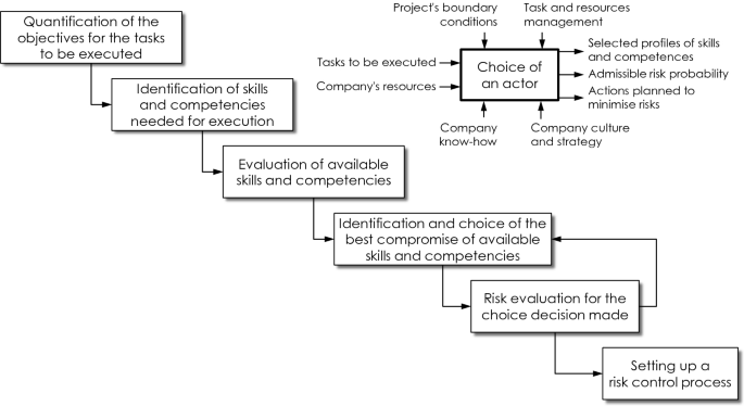
Target process [MeSC-2005]
-
The Decision Card for choice of actor that helps to approach the Target Process and allowing a capitalization of the processes and the decision taken (Fig. 15.35).
Fig. 15.35 
Decision card for the choice of an actor [MeSC-2005]


Due to these tools, SACADO is useful when decisions have to be taken.
The main steps of the Target Process correspond to the following six questions:
-
1.
What are the tasks to be performed by the actor to be chosen and in what environment?
-
2.
What are the necessary skills and competencies?
-
3.
Which skills and competencies are available?
-
4.
For the choice of actor: What is the best compromise in terms of quality, cost and time?
-
5.
What are the risks (quality, cost, time) that the actor to be chosen could cause to the project?
-
6.
Is there a process for controlling the actor chosen in relation to these risks or a risk eradication action plan to be put in place?
To help the decision maker to follow the Target Process, a decision card to support the decision process, Fig. 15.35. The decision card contains the key information that characterize a project:
-
The project context,
-
Who is the customer at which date and who is the contractor at which date?
-
The tasks to be performed, quantified in terms of quality objectives, cost and time,
-
The skills required (knowledge, know-how and attitude) for these tasks,
-
The potential actors and the chosen actor with the reasons of the choice,
-
The risk assessment depending on the skills of the chosen actor in relation to the skills required and the tasks to be performed. If a plan of actions is set up, it appears here. The responsible actor and the date of completion are specified for each risk and for each action,
-
A quantified assessment of the results, with the gaps in terms of quality, cost and time of the various actions carried out.
This card also makes it possible to analyse a dysfunction that appeared in a past decision.
In order to obtain a global vision of the dysfunctions in the process of choice of actor of a company, it is recommendable to widen, in a second time, the analysis of a dysfunction with the analysis of a series of dysfunctions and to deduce from it a recurrence or a typology. The study of all the projects of a company, or at least of a part, makes it possible to determine the main and most influential categories of dysfunctions corresponding to the problems related to the organization of the company.
15.9 Co-Creation: A Catalyst to the IDE Development Process
In order to systematize and optimize the product development process from an IDE point of view, it is necessary to articulate and to integrate both human and material resources, processes and results as well as the complete life cycle of the product. IDE’s potential to systematize and to articulate the product development processes is undeniable. IDE also identifies and articulates the resources of the people within these processes. But what is the input at the beginning of IDE? How do the processes get started?
15.9.1 Co-Creation as Input to Integrated Design Engineering
Current trends, including global interconnections, the flow of information, and the speed with which things are changing in a VUCAFootnote 29 context [BeLe-2014], challenge whether the procedures of IDE are sufficiently flexible and well-aimed to be competitive and to generate benefits not just in the marketplace, but also for making improvements in the quality of people’s lives.
In this sense, it is not enough to design a product correctly (effectivity), but rather one has to endeavour to design the right product (efficiency). As Buxton stated “There is an emphasis on balancing the back-end concern with usability and engineering excellence (getting the design right) with an up-front investment in sketching and ideation (getting the right design)” [Buxt-2007, Meer-1994]. To design the right product, it is not enough to focus on traditional design processes, but in fact it is necessary to explore the input to a traditional design process. The pre-design stage, also known as Front End Innovation (FEI) or the Fuzzy Front End (FFE) [HRSM-2016], is the place where ideas are generated first, and then design opportunities are identified, evaluated and chosen, before the concept that is to be developed is selected [StMS-2016], Fig. 15.36.

The fuzzy front end and the traditional design development process (based on [Sand-2019])
In the pre-design stage, the purpose is to actively integrate the future users of a product and the key stakeholders (clients, providers, suppliers, etc.) in the development of the product in a joint exploration process in order to identify problems and possible solutions and to explore opportunities for future products. In the pre-design stage, the use of co-creation approaches, tools, and activities allow future users to be aware of and reflect upon their daily lives in order to express their ideas [MoTo-2013] regarding what their future lives might entail.
In this context, co-creation is an approach that facilitates acts of creation to be experienced simultaneously by designers in collaboration with non-designers. This approach changes the paradigm from “designing for people” to “designing with people” and it changes the designer’s role from the expert to the facilitator of the creativity of others [Sand-2019]. It is a special case of collaboration where the intention is to create something new [SaSi-2009], with the goal of meeting both needs and dreams of the future users [SaSt-2008]. In doing so, it is necessary to be guided by the doubting users, the unadjusted, the uncomfortable among them as well as by all those who ask questions and who do not avoid them [Lott-2019]. In this way, the results of a co-creation process may result in a product, service, interface or perhaps something else, where the ideas of all participants are integrated so that everyone is able to participate from a perspective of horizontalityFootnote 30 [SaSt-2008]. This can be seen in the definition of co-creation developed by Ramaswamya and Ozcan [RaOz-2018]. This definition describes co-creation as a level of “enactment of interactional creation across interactive systems-environments (afforded by interactive platforms) entailing and agencingFootnote 31 engagements and structuring organisations”.
Co-creation is also promoted by the dematerialization/virtualization of processes, prototypes and products resulting and increasing from digitalization. This allows product development to be accelerated in such a way that feedback from those involved can be implemented without (major) delay and the new results can be assessed immediately, so that one can claim that the logic of the beta version is transferred from the software to the hardware [Jans-2019].
Three main methodological approaches are defined for the implementation of a co-creation process:
-
1.
Making (M) techniques and tools enable people to give shape to their ideas and to make the process tangible. For example, one can use blocks, clay, and pipe cleaners to create simple prototypes of future products.
-
2.
Telling (T) techniques and tools enable people to talk about what they make. For example, people can tell stories about how they would like to live in the future by using their simple prototypes of future products.
-
3.
Enacting (E) activities enable people to show how they would use their future prototypes [SaBB-2010]. For example, people can role-play or use improvisation to enact their dreams for future ways of living.
Studies like those of Orcik et al. [OrTA-2013] and Hesmer et al. [HTWB-2011] identified key elements of the co-creation process in different phases of the product’s life cycle, together with groups of co-creators that are most relevant in different product development phases. Due to the complexity of addressing these different scenarios, development environments (e.g. large and small companies, investment goods and consumer goods, etc.), and types of co-creators the focus in this section will be on the pre-design stage where co-creation can be used to conceptualize the input to the IDE process, Fig. 15.37.

The co-creation journey within the fuzzy front end (FFE)
There are many similarities between the IDE approach and the approach of co-creation. Most notably are the facts that both are human-centred approaches that are described in processes that apply at all stages of a product, a system or a service life cycle. Both approaches are based on experiences that derive from a large number of projects and relationships that have taken place over the years in industry. Where co-creation differs from IDE is in its focus on the very early front end of the innovation process from a participatory perspective.
In this conceptualization, the attributes that are in play are not addressed like a checklist but rather as options that invite the future users to explore those attributes that are significant for them. Following this line, Russo-Spena and Mele [RSMe-2012] describe the first stage of their co-creation model as “co-ideation”, and this is developed in the conceptual phase of the product’s development, looking to innovate through an external network of players who include not only leading users, but also “consumers, fans, customers, partners, professionals and intermediaries who actively participate in idea generation and shaping”.
15.9.1.1 The Relationship Between the IDE Product Life Cycle and the Co-creation Approach
The connection between the IDE product life cycle (PLC) and the co-creation approach is shown in Fig. 15.38, where it can be seen that, on the one hand, the co-creation process intersects the IDE model at the very beginning of the product life cycle. It provides the conceptualization that serves as the input to the activities within the product life cycle. On the other hand, it can be applied when necessary at any time throughout product development. One can say that the co-creation process is the catalyst to IDE.

Co-creation within the IDE product life cycle (c.f. Fig. 2.2)
15.9.1.2 The Role of the IDE Attributes in the Co-creation Process
The consideration of the attributes that describe a product is addressed in Chap. 2 that describes six product attributes, three fulfilment attributes, and two economic attributes, which all together describe the performance of the (future) product and the behaviour, with which the performance can be applied. How do these IDE attributes connect to the characteristics that are relevant in the pre-design stage during the co-creation process?
The three product attributes that make up Suitability (Product Gestalt, Functionality, Usability) are most often explored in the pre-design stage where co-creation activities are introduced to facilitate the codesigner’s explorations of opportunities for better ways of living in the future. For example, making techniques and tools are used to enable the codesigners to explore Product Gestalt questions such as “What might the product or service look like?” and perhaps “What perceivable information is offered?” Telling techniques and tools as well as enacting activities are used to facilitate the codesigner’s exploration of Functionality. For example, they might demonstrate what they have made by telling how it works or by presenting how to use it in its targeted environments. Codesigners do not usually address Usability in the Fuzzy Front End but they may begin to address usability issues once there is a working (or semi-functional) prototype later in the IDE process.
Additional product characteristics that are usually explored in the front end of design include Usefulness and Desirability. Usefulness addresses a codesigner’s questions such as: Does the product solve my problem? Does it address my unmet needs? Does it offer new opportunities for living? Desirability addresses questions such as: Is the product attractive? Do I like it? Do I want to own it? Do I want to use it?
The fulfilment attributes (Safety, Reliability, Quality) might also be explored in the front end of the co-creation process although they are more likely to be explored in the later stages of the design and development process, because the co-creation process is a pre-requirement stage where some of these attributes are not yet relevant. The remaining attributes (Producibility/Availability, Maintainability, Sustainability, Added Value and Return on Investment) are also relevant later in the design and development process once the thing that is to be designed has been conceptualized through front-end activities.
The purpose of the iterative process within co-creation is on defining and simulating the required or anticipated “product experience” (and thereby an important component of the customer demands) rather than on defining the attributes and requirements of the solution.
15.9.1.3 Identification of Participants in the Co-creation Process
In order to initiate the co-creation stage, the co-creators must be identified. It is particularly important and challenging to consider, who the future users might be, since it is not yet known how the product requirements will be approached by which concepts, kinds, and types of design. Who will they be? Are they common users? Will they become involved in the product’s entire life cycle or will they just play a big role in the front end? Answers to these questions will be defined depending on the scope and scale of the project. For example, in processes that are running on Web platforms without time and space restrictions, any stakeholder whose ideas can be filtered can take part [RSMe-2012]. However, a project-dependent series of restrictions must be considered when seeking high quality (i.e. new) needs at a low cost [OrTA-2013].
The selection of codesigners is important since it is with the greatest diversity of participants that the most useful results emerge in the generative phase of co-creation. In addition, it is needed to prepare the codesigners for their involvement in the co-creation process. This is usually done in the form of “homework” that is to be addressed by the participants before the co-creation session begins.
It is important for the designers to know the people who will become codesigners. It is necessary to understand their points of view. Only if “we put ourselves in their shoes”, it is possible for the designer to understand what is important to them. This may seem to be impossible, but it is this empathy of the designer that allows generating new possibilities. The ability of the designers to connect with the people who are the codesigners goes hand in hand with handling the informal and formal processes that are developed within the teams. In this sense, co-creation has to be spontaneous and any attempt towards formalization might cause a certain degree of stress.
Commitment between the designers and the codesigners and commitment to the co-creation process involves generating almost emotional bonds with the problem/need being resolved/satisfied. This bond is achieved by the motivation coproduced among those involved. It does not always involve signing a document with deadlines and attending meetings. It can be more of a feeling that is necessary to solve the problem or need.
15.9.2 The Co-creation Process
The co-creation process in the pre-design stage takes place in three main stages, Fig. 15.39.

Stages in the co-creation process at the fuzzy front end of design
-
First stage: Capacity building. In this stage both designers and the codesigners (as well as the other stakeholders in the process) get to know each other socially. This does not need to take a long time but it does need to be carefully orchestrated. The first stage will take more time and effort if the cultures of the designers and the codesigners are different from each another. Once they have had the opportunity to get to know each other, they can begin to explore how to work together. The designers serve as facilitators of the process of working togetherFootnote 32.
-
Second stage: Early front-end Co-creation. In this stage, designers and codesigners are engaging together in the participatory activities of Making, Telling and Enacting. The order of these activities will vary but what makes it important is that all three types of activities are used iteratively during the early front-end co-creation process. The designers may ask the codesigners to do some “homework” in preparation for the engagement. The results of the homework are then shared at the beginning of the meeting.
-
Third stage: Bringing everything together. The iterative activities of Making, Telling, and Enacting give continuity to the work and involve the participants directly in the design process. This allows the design team to adjust and to specify the frame of the project and to facilitate the generation of ideas. The team then creates a presentation covering the idea that is being developed, which describes this idea and the reasons why the idea is meaningful to the codesigners. The team also describes both questions and challenges that lie ahead. Finally, this output of the co-creation process within the FFE serves as input to start the product’s life cycle.
15.9.3 Case Study
This example of a co-creation process in the FFE of design a co-creation approach for elderly users was applied as a way to address one of Chile’s most concerning issues, the ageing of the population, which reflects a series of challenges that only can be solved by an interdisciplinary approach, keeping also in mind the cultural particularities and demands [BPBB-2017] and the bio-psychosocial changes of this population segment [BWLP-2017]. The objective of this co-creation process was to understand the difficulties in the day-to-day activities of the elderly so that one could know, prioritize and select the most relevant issues and then engage in the co-creation of valid solution alternatives, Fig. 15.40.

The co-creation process that was used in the case study. Nine teams of students and elderly codesigners took part simultaneously in this process. The case study describes the work of the marked team
The design students, after having received in-depth insights about the reality of the elderly nowadays, started the investigation by getting to know their elderly participant, including learning about her daily routines (everyday activities) and the problems that arise for her (identification of problems). This took place in face-to-face meetings that allowed the students to get to know their elderly codesigner before beginning to co-create with her. Together they identified and prioritized the impact of her routine activities that were associated with problems. The outcome of this process was the selection of the main problematic activity.
For example, they learned that their elderly codesigner had great difficulties bending down and getting back up again when cleaning inside her home. The students met with other project stakeholders from health institutions at the university to obtain the biomechanics knowledge needed to address such issues. They determined that the limited pushing ability to be able to stand up was caused by lumbago with sciatica that generated pain in her entire lumbar area. This area placed greater stress on her body, thus it took more time than usual for her to complete the action. Reasons for this were her spinal column that failed as the third point of support, as well as a lack of musculature, which is typical of this age and which added to arthritis and back pain.
During the ideation phase, the students created provotypes (a combination of provocative and prototypes, i.e. a prototype made to provoke reactions). The elderly participant’s reactions helped the students to make assumptions in terms of functionality and comfort. In this way they developed with her a shared understanding of the problem and possible solutions.
The students then generated a co-creation toolkit containing alternative components of varying sizes (e.g. parts and pieces with different setups or possibilities) from which their codesigner could chose, combine, and adjust. Along with this, they presented her with 3D drawings showing possible final appearances of this type of product, to get to know which one presentation she would judge as aesthetically pleasing.
The next step in the process was to prototype and to test ideas. The students learned that the provotype , in order to provide support, must be a rigid cylinder. They used the provotype for testing, which allowed them to understand and to see the implications of how the body of their elderly codesigner moved when bending down. This allowed the students to explore and to test different alternatives, considering the nature and fluidity of her movements. This iterative process took place over time, involving several sessions which gradually sensitized the elderly codesigner to have a greater state of awareness about the problem being worked on, making her an integral part of the team. In this way she had a very high degree of empowerment and trust in the process, not only to validate the idea being developed but also in the generation of this joint space for creation.
The co-creation team envisioned and made an extendible free walking stick. They explored several possibilities or principles for shortening or telescopically extending it. For example, could this be realized by analysing existing walking sticks? What was about the great collateral issues of how easy it is to carry the stick? Where would the elderly codesigner leave it when not using it? Starting from there, they looked again at her natural body reaction and analysed the moment of getting back up after bending down. They created an accessory that was anchored in the shoe at the heel area and provided, through an extendable bar complement, knee support to the elderly codesigner when she was bending over. Figure 15.41 shows some impressions of the work during the case study.

Impressions from the case study. Left: Co-creation of prototypes and model making with basic materials (i.e. rough mock-ups) to quickly generate multiple ideas focused on solving the primary problem. Middle: the most appropriate prototype. Right: practical validation of the most appropriate prototype by the elderly codesigner/future user of the product
15.10 Conclusion
The final provotype is not a designed product. It is a concept that was embodied and visualized so that the elderly codesigner was able to participate in its creation and to test out the implications for her being able to use it in the future. By using the co-creation process, the team created a provotype that addresses the IDE attributes Product Gestalt, Functionality, and Usability together with Usefulness, Desirability and Preliminary Usability. As such, it is a conceptualization approach that can well serve as a catalyst to the IDE development process.
Change history
17 December 2020
■■■
Notes
- 1.
Both effects are also referred to as “running targets”.
- 2.
The process term is used here from a purely organizational point of view. It should not be confused with the same term from production, where “process” means the sequence of technological steps and tools used for production and assembly (e.g. manufacturing process, assembly process).
- 3.
At least until the next reorganization of the company.
- 4.
Organizational networks can be configured in the same way as technical networks for coupling computer-supported systems in information technology. Their respective functions and behaviour are also comparable.
- 5.
For example, the first two generations of a minivan for up to seven passengers, marketed under the names Sharan, Galaxy and Alhambra, were jointly developed and built by Volkswagen and Ford.
- 6.
Workflows are used when processes must be reproducible, for example in change and release processes, processes for quality assurance or in accounting.
- 7.
In the automotive industry, for example, fixed variants of the components of a vehicle must be available at certain points in time in order not to endanger the start of production of a product.
- 8.
In large, “to be agile” means to be able to move quickly and easily, often following an impulse to improvise activities in a flexible way without planning far ahead.
- 9.
As to be agile means to move quickly and lightly as well as to be mentally quick, there may be a connection to the rugby terms “scrum” (short form of scrummage) and “sprint” for a short and fast run with the ball.
- 10.
A burn-down diagram is a graphical representation that shows over time the unprocessed tasks of the project and thus the work still to be done for the project.
- 11.
Meetings to summarize the results and progress of the project.
- 12.
A person, who applies tags to the artefacts being generated in order to register the technical skills necessary to develop the characteristics associated with artefact in question (see also Fig. 17.19).
- 13.
However, the different meanings of the term lean are thin, undernourished, unhealthy and scarce.
- 14.
This approach is not new: As early as 1915, Lillian M. Gilbreth focused her consulting work in companies on the avoidance of waste in a physical and a figurative sense [Lanc-2004].
- 15.
The colloquial British English term for “crowd” (both in public and in sport) is “scrum”. This name became a generic term for a certain form of quick daily exchange and consolidation of information on the results achieved since the last Scrum, especially in software development projects (see Sect. 15.3.3.2).
- 16.
This principle is also known in Sweden as the “Lagom” principle. For this term there is no direct translation in German, it can mean for example “good enough”, “not too little and not too much”, “just right”, “fair share”. The term refers to a balance of requirements and it neither has a negative meaning, nor does it claim perfection.
- 17.
This assumption should not be confused with the recommendation to work on only one thing at a time (and not several at the same time). Processing only one task at a time allows you to concentrate fully on that task and thus complete it with an appropriate result in an acceptable time. In contrast, in multitasking about 2/3 of the available human concentration power is consumed by switching between the different tasks and, before the actual processing begins, restoring the respective processing states of the individual tasks [KuSe-2008, Schw-2012].
- 18.
Further testing and assessment options are discussed in Chap. 25.
- 19.
“Simplicity” in this context means the art of minimizing the amount of work done without compromising the agreed results (c.f. also Sect. 1.8).
- 20.
This is the case, for example, with an unplanned transfer of unfinished results within the framework of Simultaneous Engineering (see Fig. 17.4).
- 21.
This name originated from the last name of the Gilbreth couple read backwards.
- 22.
The works of the Gilbreth couple can be viewed at Purdue University (West Lafayette, www.purdue.edu) and in part at the Boston Public Library (www.bpl.org). They are also available from the American Institute of Industrial Engineers, IIE (http://www.iienet2.org/Default.aspx).
- 23.
In her doctoral thesis, Freisleben uses a knowledge-based procedure model with only 51 process elements to model new design from any industry branch. Accordingly, even fewer process elements are required for modelling adaptation design or variant design. Almost 100 methods, procedures, tools and aids are provided for the process elements [Frei-2001].
- 24.
In the morphological box (also called morphological matrix)a task is divided into subtasks. These are entered in the first column of the box. Solution alternatives are developed for each subtask and entered in the respective line. To create a new solution, individual solution alternatives are combined for each subtask. Only those combinations are possible in which the respective material, energy and information flows are compatible between the two meeting solution alternatives. The combinations can be evaluated in different ways, for example with the connection matrix according to Roth [Roth-1982].
- 25.
- 26.
This traceability plays an important role in questions of product liability. The company must be able to prove that it has not made any mistakes in the development, manufacture and sale of the product (proof of relief in the Product Liability Act [EU-85/374]).
- 27.
A dysfunction is a disturbance or a malfunction that leads to an impaired or abnormal function and/or behaviour of a creature or an artefact.
- 28.
Abbreviation of Système d’Aide au Choix d’Acteur et aux Décisions d’Organisation (supporting system to select actors and to support decisions in organizations).
- 29.
VUCA is a combined acronym for Volatility, Uncertainty, Complexity and Ambiguity. The same acronym also serves for describing a strategy to overcome the problems of volatility, uncertainty, complexity, and ambiguity. In this case VUCA reads as Vision, Understanding‚ Clarity, and Agility.
- 30.
Horizontality is a structuring principle that doesn’t come from hierarchical (i.e. vertical) structures, in which the hierarchy regulates access to information, resources, positions of power, etc., but from flat and equivalent (network) structures, in which the principle of diversity applies to all participants and in which there is no centre, no single individual or organization that may speak in the name of the whole network and in which the only decision-making process is consensus [Wain-2007].
- 31.
The meaning of “agencing” (based on the French word “agencer”, of which the English translation can be “to contrive” or “to arrange” something) is both “organizing” and “giving agency”; it thus designates a process by which various entities are connected, coordinated, and put in motion [Oxfo-2019].
- 32.
For more about Creative Capacity Building, see e.g. [DrSG-2017].
- 33.
This description is based on results from the User Centred Design Workshop 2018 at the Universidad del Bío-Bío (Chile). the student team to perform this case study consisted of N. Olivera, C. Crino, and R. Valladares. the study was a part of a research work supported by the CONICYT FONDECYT 1171037 project.
References
Adams, R.S., Turns, J., Atman, C.J.: Educating effective engineering designers: the role of reflective practice. Des. Stud. 24(3) 2003
Manifesto for Agile Software Development. 2001, https://agilemanifesto.org. Access Jan 2019
Barton, N.H., Briggs, D.E.G., Eisen, J.A., Goldstein, D.B., Patel, N.H.: Evolution. Cold Spring Harbor Laboratory Press, Cold Spring Harbor (2007)
Bennetta, N., Lemoine, G.J.: What a difference a word makes: understanding threats to performance in a VUCA world. Bus. Horiz. 57(3), 311–317 (2014)
Björk, E.: Insider action research applied on development of assistive products. Ph.D. thesis, Otto-von-Guericke-University, Magdeburg, Germany (2003)
Björk, E.: Why did it take four times longer. Int. J. Technol. Disabil 21(4), 159–170 (2009)
Boehm, B.: A spiral model of software development and enhancement. IEEE Comput. 21(5), 61–72 (1988)
Briede-Westermeyer, J.C., Pérez-Villalobos, C., Bastías-Vega, N., Bustamante-Durán, C., Olivera-Morales, P., Parra-Ponce, P., Delgado-Rivera, M., Cabello-Mora, M., Campos-Cerda, I.: Interdisciplinary experience for the design of health care products. Rev. Med. Chile 145, 1289–1299 (2017)
Burchardt, C.: Ein erweitertes Konzept für die Integrierte Produktentwicklung. Dissertation Otto-von-Guericke-Universität Magdeburg (2001)
Buxton, B.: Sketching user experiences: getting the design right and the right design, 448 pages. Morgan Kaufmann Burlington, MA (2007)
Briede-Westermeyer, J.C., Leal-Figueroa, I., Pérez-Villalobos, C.: Designers, are they stars of facilitators of interdisciplinary work? The co-creation and consensus in the design of products for elderly. Revista 180(40), 20–29 (2017)
Clarke, P.M., O’Connor, R.V., Yilmaz, M.: In search of the origins and enduring impact of Agile software development, ICSSP ‘18, Gothenburg, Sweden (2018)
Cooper, R.G.: Winning at new products. Addison-Wesley Pub. Co., Reading (1986)
Cooper, R.G.: Top oder Flop in der Produktentwicklung - Erfolgsstrategien: Von der Idee zum Launch. Wiley-VCH-Verlag, Weinheim (2002)
Crilly, N.: The structure of design revolutions: Kuhnian paradigm shifts in creative problem solving. Des. Issues 26(1), 54–66 (2010)
Dahm, M., Haindl, Chr.: Lean management six sigma—Qualität und Wirtschaftlichkeit in der Wettbewerbsstrategie. Schmidt Verlag, Berlin (2009)
Design Council: The design process. The ‘double diamond’ design process model. 2005. http://webarchive.nationalarchives.gov.uk/20080821115409/designcouncil.org.uk/en/about-design/managingdesign/the-study-of-the-design-process/, Zugriff 5. Juni 2016
Design Council: Eleven lessons: Managing design in eleven global companies. 2007. https://webarchive.nationalarchives.gov.uk/20080821071149/http://www.designcouncil.org.uk/Documents/About%20design/Eleven%20Lessons/Desk%20Research%20Report.pdf, Zugriff 4. Juli 2019
DIN 69901, Projektmanagement – Projektmanagementsysteme. Beuth, Berlin (2009)
Dörner, D.: Gruppenverhalten im Konstruktionsprozess, In: VDI-Berichte Nr. 1120, VDI-Verlag Düsseldorf, Seite 27–38 (1994)
Drain, A., Shekar, A., Grigg, N.: Involve me and I’ll understand: creative capacity building for participatory design with rural Cambodian farmers. CoDesign, https://doi.org/10.1080/15710882.2015.1399147, (2017)
Ehrlenspiel, K., Meerkamm, H.: Integrierte Produktentwicklung, fünfte überarbeitete und erweiterte Auflage. Carl Hanser Verlag München (2013)
Ehrlenspiel, K.: Integrierte Produktentwicklung, dritte aktualisierte Auflage. Carl Hanser Verlag München (2007)
Richtlinie 85/374/EU des Rates der Europäischen Union vom 25. Juli 1985: Haftung für fehlerhafte Produkte. Erlassen am 25. Juli 1985. Inkrafttreten als Bundesgesetz in der Bundesrepublik Deutschland am 01. Januar (1990)
Freisleben, D.: Gestaltung und Optimierung von Produktentwicklungsprozessen mit einem wissensbasierten Vorgehensmodell. Dissertation Otto-von-Guericke-Universität Magdeburg (2001)
Fricke, G.: Successful individual approaches in engineering design. Res. Eng. Des. 8(3), 151–165 (1996)
Freund, J., Rücker, B., Henninger, T.: Praxishandbuch BPMN 2.0, 2. aktualisierte Auflage 2010, Hanser München, pp. 8–17, 28 (2010)
Gero, J. S., Kannengiesser, U.: The situated function–behaviour–structure framework. Des. Stud. 25(4), 373–391 (2004)
Grochla, E.: Unternehmensorganisation: neue Ansätze und Konzeptionen. Westdeutsche Verlagsgesellschaft, Hamburg/Opladen (1983)
Extreme-programming. https://www.slideshare.net/bilalhashmishah/extreme-programming-12836919. Access 18 Juli 2019
Highsmith, J.: Agile project management: creating innovative products. Addison Wesley, USA, 2004 and 2009
Hock, T.: Integrated product development. In: Proceedings in Engineering Science 22. Seite 189–198. Indian Academy of Science, Bangalore (1997)
Holmdahl, L: Complexity aspects of product development, Ph.D. thesis, Otto-von-Guericke-University, Magdeburg (2007)
Hoda, R., Salleh, N., Grundy, J.: The rise and evolution of Agile software development. IEEE Softw. (2018)
Heck, Rittiner, Steinert, Meboldt Iteration-based performance measurement in the fuzzy front end of PDPs. Proc. CIRP 2016, Elsevier 50(2016), 14–19 (2016)
Hesmer, A., Trebels, J., Wiesner, S., Brenken, B., Thoben, K.-D: Introducing a co-creative innovation environment for extended products. In: 17th International Conference on Concurrent Enterprising, pp. 1–8, Aachen (2011)
Hubka, V., Eder, W.E.: Theory of technical systems and engineering design synthesis. In: Engineering Design Synthesis, pp. 49–66. Springer, London (2002)
Jansen, St. A.: Die Enkel-Tauglichkeit kommt wieder. Interview in brand eins 21(2019)11, S. 100–101 (2019)
Juran, J.M.: Quality Control Handbook. McGraw-Hill, New York (1951)
Kannapan, S.M.; Bell, D.G.; Taylor, D.L.: Structuring information and coordinating teams in product development. In: 5th International Conference on Design Theory and Methodology, Seite 233–242, Albuquerque (1993)
http://kshitijyelkar.blogspot.com/2015/11/the-agile-scrum-framework.html. Access July 17 2019
Küstenmacher, W.T., Seiwert, L.J.: Simplify your life. Knaur München (2008)
Lancaster, J.: Making Time. Lillian Moller Gilbreth – A Life Beyond “Cheaper by the Dozen”. Northeastern University Press, Hanover, USA (2004)
Landgraff, R.L.: The Cross Functional Team Approach to Product Development. Conference on Managing in a Global Competitive Environment, Seite 45–48, Pittsburgh (1989)
Lange, K.W.: Das Recht der Netzwerke - Moderne Formen der Zusammenarbeit in Produktion und Vertrieb. Verlag Recht und Wirtschaft, Heidelberg (1998)
Day to day life on an XP team. https://www.laramind.com. Access July 18, 2019
Laseau, P.: Graphic Problem Solving for Architects and Designers. Wiley, New York (1986)
Lawson, B.: What Designers Know. Routledge, New York (2004)
Lettl, C., Hienerth, C., Gemuenden, H.G.: Exploring how lead users develop radical innovation. Opportunity recognition and exploitation in the field of medical equipment technology. IEEE Trans. Eng. Manag. 55(2), 219–233 (2008)
Le Moigne, J.L.: La modélisation des systèmes complexes, Dunod Ed., France (1990)
Lindlöf, L., Furuhjelm, J.: Agile beyond software—a study of a large scale Agile initiative, DESIGN 2018, Dubrovnic Croatia (2018)
Lindemann, U.: Methodische Entwicklung technischer Produkte – Methoden flexibel und situationsgerecht anwenden. Springer, Heidelberg (2009)
Lotter, W.: Der Durchblick – die alte Welt wollte Komplexität immer nur reduzieren. Die neue erschließt sie. brand eine 21(7), S. 34–39 (2019)
Meerkamm, H.: Integrierte Produktentwicklung im Spannungsfeld von Kosten-, Zeit- und Qualitätsmanagement. VDI-Bericht 1136 VDI-Verlag Düsseldorf, S. 1–13 (1994)
Mekhilef, M., Stal Le Cardinal, J.: a pragmatic methodology to capture and analyse decision dysfunctions in development projects. Technovation 25(4), 407–420 (2005)
Møller, L., Tollestrup, C.: Creating shared understanding in product development teams. How to ‘Build the Beginning’, 134 pages. Springer, London. https://doi.org/10.1007/978-1-4471-4180-8 (2013)
Moultrie, J.: Understanding and classifying the role of design demonstrators in scientific exploration. Technovation 43–44, 1–16 (2015)
Neutschel, B.: Adaption des generischen Prozessmodells der Integrierten Produktentwicklung für den Industrieeinsatz. Interner Bericht LMI (2010)
Newman, D.: The Process of Design Squiggle. Nicht datiert, ca. https://creativecommons.org/licenses/by-nd/3.0/us/legalcode. https://thedesignsquiggle.com/, Zugriff 26. Mai (2019)
Norman, D.A., Verganti, R.: Incremental and radical innovation. Design research vs. technology and meaning change. Des. Issues 30(1), 78–96
Orcik A., Tekic Z., Anisic Z.: Customer co-creation throughout the product life cycle. Int. J. Indus. Eng. Manag. (IJIEM) 4(1), 43–49 (2013)
Ottosson, S., Kolla, S.S.V.K.: Which product development method is best for need-based new product development? In: Vajna, S. (ed.) 11th International Workshop on Integrated Design Engineering, pp. 145–155, Magdeburg (2017)
Ottosson, S.: Participation action research—a key to improved knowledge of management. Technovation—Int. J. Technol. Innov. Entrepreneurship 23, 87–94 (2003)
Ottosson, S.: dynamic product development—DPD. Technovation—Int. J. Technol. Innov. Entrepreneurship 24, 179–186 (2004)
Ottosson, S.: Frontline Innovation Management (zweite Auflage). Tervix Göteborg (2013)
Ottosson, S.: Developing Sustainable Product Innovations. Tervix Göteborg (2016)
Ottosson, S.: Developing and Managing Innovation in a Fast Changing and Complex World: Benefiting from Dynamic Principles. Springer Nature (2018)
Oxford Handbooks online, Chapter “A Theory of ‘Agencing’: On Michel Callon’s Contribution to Organizational Knowledge and Practice” (by Franck Cochoy). http://www.oxfordhandbooks.com/view/10.1093/oxfordhb/9780199671083.001.0001/oxfordhb-9780199671083-e-006. Access 2 Apr 2019
Pahl, G.: Neue Organisationsformen mit Teamarbeit. 21. Kolloquium Konstruktionstechnik: Zeitgemäßer Produktentwicklungsprozess, Magdeburg (1997)
Pikkarainen, M., Haikara, J., Salo, O., Abrahamsson, P., Still, J.: The impact of agile practices on communication in software development. Empirical Softw. Eng. 303–337 (2008)
Project Management Institute, Inc. (ed.): A Guide to the Project Management Body of Knowledge (PMBOK Guide), 5th edn. Project Management Institute, Inc., Newtown Square, PA, USA (2013)
Project Management Institute, Inc. (ed.): Practice Standard for Work Breakdown Structures, 3rd edn. Project Management Institute, Inc., Newtown Square, PA, USA (2019)
Prinzler, H.: Lean Development—Das 9 „P“-Modell. Zusammenhang zwischen den wesentlichen Prozessschritten im Produktenstehungsprozess. In Marcus Evans (Herausgeber): Optimierung des Engineering-Prozesses in produzierenden Unternehmen, Düsseldorf (2011)
Ramaswamya, V., Ozcan, K.: What is co-creation? An interactional creation framework and its implications for value creation. J. Bus. Res. 84(2018), 196–205 (2018)
Roth, K.: Konstruieren mit Konstruktionskatalogen. Springer, Berlin (1982)
Royce, W.: Managing the development of large software systems: Concepts and techniques. Western Electric show and Convention Technical Papers, (1970)
Russo-Spena, T., Mele, C.: “Five Co-s” in innovating: A practice-based view. J. Service Manag. 23(4), 527–553 (2012)
Sanders, E.B.-N., Brandt, E., Binder, T.: A framework for organizing the tools and techniques of participatory design. In: Proceeding PDC ‘10 Proceedings of the 11th Biennial Participatory Design Conference Sydney, pp. 195–198, Australia (2010)
Schmidt, T.S., Atzberger, A., Gerling, C., Schrof, J., Weiss, S. Paetzold, K.: Agile development of physical products: an empirical study about potential transition and applicability, ISBN: 978-3-943207-38-5, Available at: www.unibw.de/itpe, Report 2019, University of the German Federal Armed Forces, Munich, Germany (2019)
Sanders, E.B.-N.: Is sustainable innovation an oxymoron? In: Stebbing, P., Tischner, U. (eds.) Changing Paradigms: Designing for a Sustainable Future, Birkhäuser Publishers (BIRD Series) (2019)
Sanders, L., Simons, G.: A social vision for value co-creation in design. In: Open Source Business Resource (2009)
Sanders, E.B.-N., Stappers, P.J.: Co-creation and the new landscapes of design. Co-Des. 4(1), 5–18 (2008)
Schabacker, M.: Bewertung der Nutzen neuer Technologien in der Produktentwicklung. Dissertation Otto-von-Guericke-Universität Magdeburg (2001)
Schwaber, K.: SCRUM development process. In: 10th Annual Conference on Object-Oriented Programming Systems, Languages and Applications (1995)
Schwartz, T.: The magic of doing one thing at a time. In: Harvard Business Review. March 14, 2012. https://hbr.org/2012/03/the-magic-of-doing-one-thing-a.html#, Zugriff 13. April 2019
www.scruminc.com. Access 17 July 2019
Scrum-Scrum.: https://www.scruminc.com/scrum-of-scrums/. Access Apr 2019
Simonton, D.K.: Creativity as blind variation and selective retention. Is the creative process Darwinian? In: Psychological Inquiry, pp. 309–328 (1999)
https://slidemodel.com/templates/extreme-programming-powerpoint-templates. Access 18 July 2019
Stal-Le Cardinal, J.: Approche systémique de la prise de décision en entreprise. Thèse de Doctorat, École Centrale Paris (2009)
Stevanović, M., Marjanović, D., Štorga, M.: Managing the process of preparation for product development - ideas assessment and evaluation. In: Marjanovic, D., Storga, M. (eds.) Proceedings of DESIGN 2016 Dubrovnik, Zagreb 2016 (DS 84), pp. 1155–1164 (2016)
Stark, J., Vajna, S.: Business Process Reengineering vor der Einführung eines EDM-Systems. Océ GmbH Mülheim (1996)
Surendra, N.C., Nazir, S.: Agile development: exploring what practitioners want to know. J. Softw. Eng. Appl. 11, 1–11 (2018)
Szélig, N., Schabacker, M., Vajna, S.: Suitable methods for process modeling and process optimization. In: Lindemann, U., Venkatraman, S., Kim, Y.S., Lee, S.W. (Herausgeber): Proceedings of ICED 13, Seoul Korea, Vortrag 176 (2013)
Tuckman, B.: Developmental sequences in small groups. Psychol. Bull. 63, 348–399 (1965)
Vajna, S.: Dynamic process navigation. In: Penninger, A.: Proceedings of 9th International Conference on Heat Engines and Environmental Protection, Seite 229–240 (2009)
Vajna, S., Kittel, K., Bercsey, T.: Designing the solution space for the Autogenetic Design Theory (ADT). In: Marjanovic, D., Storga, M., Pavkovic, N., Bojcetic, N. (Eds.): Proceedings of DESIGN 2010, the 11th International Design Conference. Dubrovnik, pp. 1441–1450 (2010)
Vajna, S., Clement, S., Jordan, A., Bercsey, T.: The autogenetic design theory. An evolutionary view of the design process. J. Eng. Des. 16(4), 423–440
VDI-Richtlinie 2222 Blatt 1: Konstruktionsmethodik – Methodisches Entwickeln von Lösungsprinzipien. VDI, Düsseldorf (1997)
Vier, C.: Unternehmenstransformation und Netzwerkorganisation. Verlag Paul Haupt, Bern (1996)
Vajna, S., Weber, C., Zeman, K., Hehenberger, P., Gerhard, D., Wartzack, S.: CAx für Ingenieure, eine praxisbezogene Einführung, 3. Auflage. Springer, Heidelberg (2018)
Wahrig, G.: Deutsches Wörterbuch. Bertelsmann Lexikon-Verlag Gütersloh (1978)
Wainwright, H.: Prinzipien und Herausforderungen. Rosa Luxemburg Stiftung 2007, https://www.rosalux.de/publikation/id/1460/prinzipien-und-herausforderungen. Access 28 July 2019
Walton, M.: Strategies for Lean Product Development. Lean Aerospace Initiative, MIT Boston, Center for Technology, Policy, and Industrial Development (1999)
Wiendahl, H.P.: Betriebsorganisation für Ingenieure, 8. überarbeitete Auflage. Hanser (2014)
XP.: http://www.extremeprogramming.org/ Access Apr 2019
Zwicky, F.: Entdecken. Forschen im morphologischen Weltbild, Droemer Knaur Verlag München Zürich, Erfinden (1966)
Author information
Authors and Affiliations
Corresponding author
Editor information
Editors and Affiliations
Rights and permissions
Copyright information
© 2020 Springer Nature Switzerland AG
About this chapter

Cite this chapter
Vajna, S., Ottosson, S., Rothkötter, S., Stal-Le Cardinal, J., Briede-Westermeyer, J.C. (2020). Integration of Processes and Organizations. In: Vajna, S. (eds) Integrated Design Engineering. Springer, Cham. https://doi.org/10.1007/978-3-030-19357-7_15
Download citation
DOI: https://doi.org/10.1007/978-3-030-19357-7_15
Published:
Publisher Name: Springer, Cham
Print ISBN: 978-3-030-19356-0
Online ISBN: 978-3-030-19357-7
eBook Packages: EngineeringEngineering (R0)