
Abstract
The four main types of WIG design each use a different approach to aerodynamic support at zero and slow speeds. This is partly due to the primary design target – the cruise performance of each craft type.
Access provided by Autonomous University of Puebla. Download chapter PDF
Keywords
These keywords were added by machine and not by the authors. This process is experimental and the keywords may be updated as the learning algorithm improves.
Introduction
The four main types of WIG design each use a different approach to aerodynamic support at zero and slow speeds. This is partly due to the primary design target – the cruise performance of each craft type.
The classic WIG employs geometry for the main lifting wing with a large inlet and tapered plan form that captures the incoming air as efficiently as possible and converts as much as possible the kinetic energy into static pressure. To create the lift it has to travel forward. The static pressure build-up is partial and most effective when the ground clearance is very small. The approach to design these craft is to optimise the geometry of the lifting wing to achieve lowest practical take-off speed consistent with the desired cruise speed.
The PARWIG employs bow thrusters, either propellers for smaller craft or gas turbines for larger craft, which blow over the main wing and provide lift from the velocity of the thruster jet. The lifting force is a complex combination of normal aerodynamic lift from the wing’s upper and lower surfaces, lift from increased static pressure under the main wing and, possibly, a Coanda effect due to circulation around the airfoil. An ACV-type air cushion as such is not formed under the wing, rather, there is an additional lift from static pressure build-up due to airflow deceleration as it passes under the wing.
PARWIG using jet thrusters also derive some lift from deflection of the jet flow itself when the jet is deflected downward, directly impinging on the ground, and then on the underside of the lifting wing. There will be two components to this force, first the vertical component of the jet thrust itself, second the reaction from the ground deflection (flow reversal, with loss of velocity and generation of a static pressure) and, third, the same reaction as the jet contacts the under surface of the wing and is deflected back downwards. The first component is important to consider due to its location in the craft bow, while the second and third components will be much weaker, but still need careful assessment.
PARWIG performance targets are normally for a high cruise speed, requiring a rather streamlined design. This configuration is in conflict with a low take-off speed, and hence the approach for bow thrusters that enhance the main-wing performance, rather than creating a full air cushion.
The DACWIG extends the approach of the PARWIG by forming the main wing and side buoys to form a cavity that can more effectively trap the incoming air and form a cushion even at zero speed. The thrusters will still create additional forces when the air jet is deflected downward, similar to a PARWIG. The cushion formed still has a large air leakage forward under the wing leading edge. This reduces as craft speed increases towards take-off. Once the arrangements necessary for an effective air cushion have been adopted, it is clear that the design for extreme speed is not appropriate and so DACWIG performance targets fall in the mid range of cruise speed.
The DACC takes cushion formation one stage further by including skirt-type seals. A DACC is normally designed to stay in strong ground effect so that the cushion seals can remain effective at all operation speeds, and craft support remains a combination of aerodynamic lift and cushion lift at cruise speed.
In this chapter, we will focus on the static pressure generated under the main wing at zero and slow speeds by bow thrusters, and in particular its application for DACWIG and DACC. Both of these craft have a configuration including a main lifting wing, side buoys and trailing edge flaps arranged so that the bow thrusters can create an air cushion to lift the craft off the ground even at zero-forward speed. The air cushion then allows take-off into the strong ground effect region at relatively slow speed, and reduces the drag peaks in the transitional phases.
Hovering Performance Requirements
Manoeuvring and Landing
Amphibious capability (slow-speed manoeuvring, take-off and landing over land or water) is enabled for DACC and DACWIG through having a clear air gap between the base plane of the main hull and side buoys with the ground or water when hovering statically. If no flexible skirt is installed under the side buoys, the clear air gap (daylight clearance) when hovering statically is particularly important to protect the hull and side buoy structures against ground impact. Improved obstacle clearance can therefore be achieved by installing inflatable skirts similar to those for a hovercraft, if the WIG hull geometry is suitable. The main hull and side buoys will need landing pads installed if no rolling wheels are fitted for overland manoeuvring off cushion.
Low-Speed Operations
Craft sometimes need to manoeuvre at low speed in narrow waterways, rivers or other areas close to harbours and terminals or military bases. PARWIG craft have high resistance and required power rating to operate in the hull-borne mode for low-speed manoeuvring and so are only suited to open-water operation. DACC and DACWIG can use hovering mode for manoeuvring in confined conditions with minimum resistance, zero draft and relatively powerful response to controls. Over water, it is not necessary to have a clear air gap, as this creates a great deal of spray at low speed. Similar to an ACV, so long as the air cushion pressure is sufficient to support the weight and depress the internal water surface, controllability should be fine.
Hump Speed Transit and Take-Off into GEZ
The resistance curve of both PARWIG and DACWIG has significant peaks at hump and take-off speeds [1]. At hump speed, the resistance is two or three times that at cruising speed, while just after take-off the drag reduces to a minimum. Since the drag at hump speed is even larger than at design speed, the ability for passing through hump speed is the primary powering criteria for WIG.
Figure 1.13 shows a drag curve of a PARWIG model both on calm water and in a seaway, with and without air injection, i.e. with and without bow thrusters providing pressurised air into the air channel under the main lifting wing. It can be seen that the drag with air injection is significantly lower than that without the air injection both on calm water and in waves.
Figure 1.14 shows the aerodynamic and hydrodynamic lift force on a craft during take-off without and with air injection. Air injection under the wings of an Ekranoplan substantially decreases the hydrodynamic drag during take-off and, in addition, weakens the hydrodynamic impact force and vertical acceleration in waves. In the figure, L is the aerodynamic lift force and W is the weight of the craft. In the take-off run of a seaplane, hydrodynamic forces prevail – the forces acting on the floats and hull. A PARWIG has much lower hydrodynamic loads than a seaplane due to the dynamic air cushion support and damping. This has been verified by model experiments.
Air injection therefore improves the lift force and also reduces drag particularly through hump speed.
Seakeeping
There are three criteria to judge the seakeeping qualities of a WIG:
-
Impact loads from waves acting on the hull before and during take-off
-
Vertical acceleration of craft operating over waves
-
Ability to accelerate through hump speed and take-off over waves
PARWIG Theory from the 1970s
Hovering performance has an important influence on the hump drag and so the ability to accelerate through hump speed and take-off. In addition, the seakeeping at speeds up to take-off are much improved with effective low-speed air cushion support. Due to lower hump drag, a craft with an effective air cushion can be designed with lower power, since the overall powering for WIG is controlled by hump drag and take-off, rather than cruise speed.
In the early 1960s, a joint Navy/Army programme investigating the feasibility of employing ground effect for high-speed marine craft was set up in the USA. Reference [2], and reference 10 from Chapter 1 both proposed that power-assisted ram air lift might reduce take-off speed and impact loads acting on the hull during operation in waves. The concept proposed included propulsors in front of the wing so the efflux from the propulsors was blown into the channel made by the wing, flap and endplates. It was proposed that static lift of over six times the thrust of the thruster could be produced by a PARWIG configuration while recovering 80% of the installed thrust for forward acceleration.
The potential flow theories and turbulent jet theory are described as follows:
The flow momentum model for a PARWIG is illustrated in Fig. 4.1. The nomenclature is as follows:
- M 0 :
-
Jet momentum of thruster
- M 1 :
-
Horizontal momentum of thruster flow entering cavity
- M 2 :
-
Horizontal momentum of airflow leaving cavity under flap
- M 3 :
-
Momentum of jet flow deflected over main wing
- M 4 :
-
Momentum from reverse airflow from air curtain
- V 0 :
-
Thruster jet airflow velocity
- V s :
-
Average velocity of jet inside air cushion
- V 1 :
-
Velocity of jet entering air cushion
- V 2 :
-
Velocity of jet leaving air cushion
- t 0 :
-
Thruster jet thickness
- t 1 :
-
Jet thickness at ground contact
- t 2 :
-
Gap between the lower tip of flap and ground
- h :
-
Flying height of PARWIG (measured to trailing edge of main wing)
- θ :
-
Thruster jet inclination angle
- β 3 :
-
Angle of jet deflected over wing, assumed at V 0
- C :
-
Chord length of wing
- ρ a :
-
Air density
- Re:
-
Reynold’s number, Re = Vc/ν a, where c is the relevant length dimension
- ν a :
-
Dynamic viscosity coefficient of air
According to the conservation of horizontal momentum,


Airflow momentum of a WIG model
If we neglect the momentum loss in the jet flow due to its jet inclination, then
so
We assume that the pressure and velocity under the wing are uniform, so that
where P c is the static pressure and P 3 is the dynamic pressure under the wing. If we assume that V s is uniform, the equilibrium equation of horizontal momentum at the trailing edge flap and under the wing can be written as:
where D r is the drag due to the flap, i.e. \(D_{\rm{r}} = \int_{t_2 }^h {(P - P_{\rm{a}} ){\rm{d}}y}\)
Further, if we assume that the flow under the wing is one dimensional, then
According to the law of continuity of flow, then
so Equation (4.5) becomes
From Equation (4.4), we have
The wing lift per unit width can be written as \(L = P_{\rm{c}} \cdot C\), and using Equations (4.6) and (4.7), we have
The turbulent mixing injection effect can be described as a two-dimensional turbulent flow with a decaying velocity distribution from the origin to the wing tip. Using (’) to represent coordinates measured from the centreline and perpendicular to it, the velocity distribution across the span is
where
and
Using Equation (4.10),
If we substitute Equation (4.12) into Equation (4.2), then we have
The flow rate to the wing can be written as
The two-dimensional turbulent jet velocity distribution can be written after some manipulation as
where \(\overline t\) represents equivalent flow thickness, and \(\overline t\) = (1 + cos θ) t 1
Substitute this into Equation (4.8), and finally we have
where
In summary, the wing lift per unit span L is a function of
- M 1 :
-
The flow momentum at the position before the air channel
- h :
-
Flying height of the main wing measured between the lower surface of main wing and ground
- C :
-
Chord length of main wing
- t 2 :
-
Distance between the lower tip of flap and ground
- t 0 :
-
Efflux thickness at the origin
- θ :
-
The inclination angle of the thruster jet
Lift and drag predictions derived from testing results are given in references [2] and Chapter 1 [10]. The model under test is shown in Fig. 4.2.


US Navy PARWIG model in towing tank – may need to delete or substitute
In order to simplify the calculation above, if we take M 1 = M 0 and M 1 = t(1+ cos θ)/2, and t = πd 2/4b c, then the wing total lift can be calculated simply. However, there are some interesting problems with this formula, e.g.:
-
1.
A specific air gap at the stern flap is assumed, however, actually the air gap when hovering statically is close to zero. In such a case, Equations (4.8) and (4.9) will be indeterminate. The physical phenomenon will be very similar to an air cushion vehicle. The equation can alternately be written as
$$M_1 \cos \theta - M_3 \cos \beta _3 + M_4 = P_{\rm{c}} \cdot {\rm{h}}$$This formula may be more suitable for a PARWIG that is unable to operate over ground without landing gear. For a craft without amphibious ability, the function of static air cushion lift is then to lighten the pressure on the landing gear, and improve take-off performance. In this case, the flaps will be opened with a definite gap t 2, so as to reduce the drag from the flaps.
-
2.
It is found that lift increases with efflux momentum M and wing chord C, and increases inversely with flying height h, and has no relation with the cushion beam. The hypothesis that the cushion pressure is only dependent upon the specific momentum of the thruster, i.e. the momentum per unit beam of cushion, is based upon the idea that the wider the cushion, the larger the cushion area and lower the specific momentum required.
This may cause a misleading result, because the mixed efflux momentum M 1 is rather different from M 0 due to the air injection, and the wide cushion beam will cause a more effective mixture of the air injection than that where the cushion is narrow. It can be shown that sometimes the wider the air tunnel, the higher the lift acting on the wing.
Therefore, these expressions may be most suited to craft with a narrow air tunnel compared with the width of jet flow, or for a multiple row of bow thrusters, as shown in Fig. 4.2. This figure shows a US Navy PARWIG model testing in towing tank. The model had a row of bow propulsors, and its corresponding turbulent mixing injection model is shown in Fig. 4.3. In this case, the expressions above may be suitable.
-
3.
In order to obtain a more effective turbulent mixing injection, the key parameters to relate position for bow thruster and wing will be X j, and h+Δh, as shown in Fig. 4.4, together with the main wing chord C, and the bow thruster jet angle θ
Fig. 4.3 
Turbulent mixing air injection with multiple rows of bow thrusters on PARWIG model
Fig. 4.4 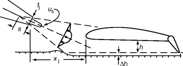
Key parameters of related positions of bow thruster and main wing
-
4.
The Coanda effect is not taken into consideration in the formula so that model test results will show higher lift than the calculations.
-
5.
On real craft and models, normally there are side buoys at the tip of the main wings and a hull located at the centre of the craft, each with finite width. In the formula above, the lift provided by such hull and side buoys are not taken into account, so as to give conservative results compared to expectations from model tests.


Static Hovering Performance of DACWIG and DACC
Introduction
The PARWIG “Orlyonok” as shown in Fig. 2.17 is a very high-speed craft, and has good aerodynamic efficiency at higher flying height. The craft is characterised by a large aspect ratio, wide span main wing, thin side buoys and short flaps. This configuration makes it very difficult to form a steady air cushion and create sufficient static air cushion lift to support the total weight of craft at slow or zero speed. The bow thrusters of this type of craft aims instead to improve the take-off performance, seakeeping quality and payload capacity, by increasing the airspeed past the main wing compared to craft forward speed over both lower and upper surfaces.
Landing and launching of craft of this type are carried out using wheeled landing gear to roll onto the launch ramp, and both bow thrusters and cruising engines for propulsion as shown in the general arrangement of Orlyonok (Fig. 2.15).
DACC and DACWIG are characterised by their hovering capability without the need for landing wheels. This is their main advantage. For this reason, the craft has the following prerequisites, similar to an ACV:
-
Bow thrusters as fans to provide enough air pressure and flow rate to feed into the air channel during the static hovering
-
Configuration of the main wings and side buoys to form a suitable static air cushion
-
Some means to adjust the bow-thruster efflux from the pressure air provider to a propulsor with acceptable propulsion efficiency at the target cruise speed
Configuration of a DACC or DACWIG
Figure 4.5 below shows a typical DACC, the “Volga 2”, and Fig. 4.6 shows a typical sketch of a DACC or DACWIG. From the figures, the prerequisite for making a steady and powerful air cushion will be satisfied by arranging the following elements in the correct configuration:


Typical DACC – the Russian Volga 2


DACWIG outline
- • Main wing::
-
main lift-supporting surface.
- • Main hull::
-
main accommodation cabin of passengers or other disposable load, and also as an additional lifting surface.
- • Side buoys::
-
(1)With main hull, they should provide enough buoyancy to support the craft weight during hull-borne operation and avoid too deep static draught such that the bow thrusters submerge into water. Ideally the bow thrusters should have a static clearance from the water surface at least 100% of the design take-off wave height.
(2)Seal the air cushion during static hovering;
(3)Providing an additional surface area for the air cushion.
- • Main-wing flaps::
-
(1)Sealing the air cushion during static hovering;
(2)Enhance the aerodynamic lift of main wing during flying operation mode through partial or full raising from the lowered-down position for hovering.
- • Thruster guide vanes::
-
To change the airflow direction to suit the need of various operation modes.
- • c/b at or b at/c::
-
Cushion length/beam ratio (where c is wing chord length and b at is width of air channel) or aspect ratio of main wing from the point of view of static hovering, similar to an ACV, the larger the cushion length/beam ratio the more effective is static hovering performance. However, high c/b at, meaning lower main-wing aspect ratio decreases the aerodynamic efficiency of the wing in flying mode so we have a trade-off problem.
- • Wing aspect ratio::
-
The aspect ratio of the whole wing is (A.R)w = b w/c, where b w = 2 ⋅ b at + b h + 2 ⋅ b sb. The main element of this aspect ratio is still b at, the breadth of the main wing, and so the trade-off problem is not significantly changed when considering the craft rather than the main-wing air channel on its own.
Static Hovering Performance of DACC and DACWIG
Simplified Physical Model
Figure 4.7 shows a typical physical model of the airflow around a DACC or DACWIG, similar to Fig. 4.1 that shows a PARWIG. The difference of the flow characteristics between PARWIG and DACC is that the flaps of the latter are fully lowered during static hovering. To simplify, the physical model can be taken as that of an ACV so long as a suitable air curtain can be generated by the bow-thruster air jet. Figure 4.8 shows a typical transverse section of an ACV.


Physical model of the airflow around a WIG in plan view


(a) A transverse section of ACV and (b) adjustment to simulate WIG flow
In the case of DACC, the model can be changed from Fig. 4.8a to b, and also taking a look at Fig. 4.7, the average pressure in the air channel P c can be obtained as follows, using the flow momentum theory based upon the unit length of transverse section of the wing. That is:
where
- P c :
-
Cushion pressure (N/m)
- ρ a :
-
Air density (N)
- t :
-
Nozzle thickness (m)
- H :
-
Cushion height (see Fig. 4.8) (m)
- h :
-
Hovering height (m)
- V j :
-
The average velocity of airflow from bow thruster (m/s)
- θ :
-
The angle between the centreline of nozzle and the craft base plan (°)
Then the total pressure at the nozzle can be expressed as
where
- P t :
-
Total pressure at the exit of nozzle (N/m)
- f P 0 :
-
Static pressure at the exit of nozzle (N/m) (=P c)
- ƒ :
-
Coefficient, according to the relative flying height h/t
Then the fan flow rate can be estimated as:
where
- Q :
-
Airflow from nozzle (m3/s)
- l :
-
Peripheral length of jet nozzle (m)
The lift power of an ACV can be estimated as:
where
- η :
-
Efficiency of fan and air duct
- η s :
-
drive system efficiency
- N L :
-
Lift power (ps)
Assuming the cushion pressure is uniformly distributed, the liftable weight will be
where
- W :
-
liftable weight (N)
- S c :
-
Cushion area (m2)
This is the basic formula for estimating the cushion pressure, flow rate and lift power of a DACC as an ACV. However, this expression cannot be used for DACWIG, for the following reasons:
-
The jet nozzle is not uniformly distributed along the transverse direction of main wing, i.e. the jet nozzle cannot be used instead of the bow thrusters.
-
The thickness is not thin enough so as to assume that the flow velocity along the exit is uniform.
-
The turbulent mixing airflow has to be taken into consideration.
-
There are air stream flows around the back surface of the wing and so the Coanda effect also has to be taken into consideration.
Practical Estimation of Static Hovering Performance of DACC and DACWIG
Theoretical calculation for estimating the static lift of a DACWIG or DACC is too complicated to rely on alone and so model experiments are normally used as the main study method and regression plots assessed from the test results to predict the static hovering performance. Both half and whole models can be used for such investigations. The half model shown in Fig. 4.9 includes the main hull and a side buoy as the endplate, and a bow blower, but without the tailplane and fin. The approach is to have a simple model and so more models for investigation at low cost. The figure shows a half model tested in a wind tunnel. Figures 4.10 and 4.11 show a DACWIG model hovering static on a rigid screen.


Half model of DACWIG tested in wind tunnel


Static hovering experiment of a WIG model on a rigid screen (front view)


Static hovering experiment of a WIG model on a rigid screen (side view)
The static hovering performance of DACC or DACWIG is then tested for a number of variable parameters, i.e. the relative position of the bow thruster with the main wing and main hull as well as side buoy. The key geometric parameters, as shown in Fig. 4.8a, are as follows:
- l btw :
-
The distance between the leading edge of main wing and vertical plane of blades of bow thruster
- b :
-
Distance between the craft centreline and bow thruster centreline
- b w :
-
Wing span
- h :
-
Flying height, the distance between base plane of hull and ground
- H :
-
Vertical distance between main-wing leading edge and the ground
- hʹ:
-
Height from the ground of centreline of bow thruster in the plane of the blade centreline
- θ :
-
Inclination angle of bow thrusters airflow
- α 0 :
-
Main-wing angle relative to keel line of craft (wing assembly angle)
For estimation of static hovering performance of the craft, some basic assumptions have to be made as follows:
-
The flaps are always lowered during static hovering.
-
The flow pattern can be assumed as shown in Fig. 4.8b.
-
The static cushion pressure P c in the air tunnel can be assumed uniformly distributed, similar to an ACV or SES. This has been validated by the test results of the MARIC craft-type “750” and Swan.
-
The air curtain will be formed under the main-wing leading edge. This air curtain is formed directly behind the bow thruster, generating reverse flow momentum M 4, and the other part of the air curtain is generated from transverse flow outward from the area covered by the thruster jet. The physical phenomena can be clearly observed both in model experiments and full-scale tests.
The jet flow from the bow thruster has to be concentrated and blown into the air tunnel at an optimum distance forward from it, and with effective barriers to contain the air cushion transversely, and at the wing trailing edge. The pressure distribution longitudinally and transversely across the main lifting wing under surface should then be similar to Fig. 4.12a,b , which show data from model tests of the “Swan” DACWIG.


(a) Transverse and (b) longitudinal pressure distributions under main wing of the Swan WIG
Then the flow momentum equation can be expressed as:
Since the H is rather large compared with h, the h may be neglected. In addition, since θ 2 has a large value (near perpendicular to the sidewall), M 2 also can be neglected. The M 3 (Coanda effect) also can be estimated by putting a coefficient on the lift caused by air cushion, then for analysis, the M 3 item can also be neglected. Then, Equation (4.21) can be written as follows:
Then
From the equations, there are some possibilities for increasing the cushion pressure and so the liftable weight may be proposed as follows:
-
The lower H is, the higher the cushion pressure generated.
-
It is most important to generate the air curtain to seal the air leakage from the air cushion at the cushion intake. From this point of view, a narrower wingspan makes it easier to maintain the air curtain in transverse direction along the wing. However, a wider span will create a larger cushion area, so this is a very interesting design challenge to optimise. Work is ongoing to develop more data for such optimisation.
-
Making an inclined angle between the centreline of bow thruster and the craft (see Fig. 4.8a) will increase the cushion pressure.
-
Lowering H gives higher cushion pressure. However, this drops down the position of the bow thruster, and thus potentially immersing the propeller into the water during hull-borne operation and take-off of craft in waves. In addition, a lower thruster position will be less efficient for thrust during ground effect flight.
-
The calculation above does not consider the turbulent mixing effect of the efflux momentum from the bow thruster, for which the theoretical calculation is very complicated, so the expressions should be considered a means for discussion only.
Since there is no bow skirt or other sealing means at the bow, the most important measure for increasing the static lift is to take steps to seal the air leakage from cushion.
The air-jet momentum from the bow thruster can be expressed as:
where
- Q :
-
Airflow rate from bow thruster (m3/s)
- A p :
-
Area of propeller disc (m2)
- q j :
-
Dynamic pressure of air jet (N/m2)
Then from Equation (4.22), the non-dimensional average cushion pressure can be expressed as:
where
- l, H, b and θ :
-
The parameters representing the geometric position of the bow thruster on the craft model, which can be found in Fig. 4.8a
- γ :
-
The inclination of flap, equal to zero in this case due to the static hovering situation of craft
In case of a fixed craft geometry and related position of bow thruster, then Equation (4.24) can be expressed simply as
where
-
$$q_{\rm{j}} = 0.5\rho _{\rm{a}} V_{\rm{j}}^2$$
-
V j is the average jet velocity of the bow thrusters
Figure 4.13 shows a typical relative cushion pressure \(\overline {P_{\rm{c}} }\) versus relative hovering height \(\bar h\). It has been found the cushion pressure drops rapidly with increasing \(\bar h\).


P c versus h of DACWIG model while flap closed
The optimum for relative position of a bow thruster and craft lines can be found by model experimental investigations. A ducted propeller (or turbofan) is often used as a bow thruster due to easy deflection of the jet fed into the air channel. In this case, the propeller thrust can be expressed as follows (Fig. 4.14)


Bow-ducted propeller sketches
In front of propeller disc,
where
- P a :
-
Relative atmosphere pressure, = 0
- P c0 :
-
air static pressure
Behind the propeller disc,
where
- P t :
-
Total pressure of propeller (N/m2)
- P c1 :
-
Static air pressure behind the propeller disc (N/m2)
The total pressure of propeller or fan, P t, can be expressed as: \(P_{\rm{t}} = k_{\rm{q}} q_{\rm{j}}\), where in general \(k_{\rm{q}} = 1.05 - 1.1\).
Then the propeller thrust can be expressed by
From the Equations (4.25) and (4.28), it is found that the propeller jet dynamic pressure and propeller thrust have the same influence on the cushion pressure of a DACWIG or DACC. From this point of view, the propeller thrust is simpler to use for estimating the lift of the craft due to its simplicity for direct measurement.
The total static lift can be expressed as
where
- L 1 :
-
Lift provided by air cushion pressure, L 1 = P c ⋅ S c
- L 2 :
-
Lift provided by Coanda effect, L 2 = L 1 ⋅ K c
- L 3 :
-
Lift provided by the vertical component of the thruster of bow thrusters, L 3 = T sin θ
- W :
-
Craft weight
- S c :
-
Total cushion area, S c = C (b h + 2b w + b sb)
It is important to note that the longitudinal centres of the three lifting force components are quite different. Craft static trim will be sensitive to the moments applied around the CG.
Since the pressure acting on the outside half-width of the base of each side buoy is close to atmospheric pressure, the supported area of the side buoy should be assumed half of the bottom area of the side buoys.
The flow rate and the power of the bow thruster (or lift fan) and lift engine can be calculated as:
where
- Q :
-
Flow rate of lift fan (m3/s)
- η p :
-
Propeller/thruster efficiency
- η t :
-
Transmission efficiency
- N :
-
Power of lift engine (kW)
Meanwhile, in order to simplify the calculation and treat the bow thruster as a ducted propeller, some useful parameters are also recommended as follows:
where
- T so :
-
Static thrust of single ducted thruster (N)
- η Ls :
-
Total static lift coefficient of air channel
- L :
-
Total lift provided by an air channel (N)
- T sc :
-
Static thrust of a single-ducted thruster in air channel (N)
- η Ts :
-
Static thrust-recovery coefficient of the ducted thruster in channel
The coefficients η Ls and η Ts are the main criteria characterising DACC’s and DACWIG’s static hovering performance. These coefficients are normally obtained from prototype or model tests. The power of the lift engine can be estimated as follows:
where
- \(\lambda _{\rm{p}}\) :
-
Propeller advance ratio, \(\lambda _{\rm{p}} = V/nD\)
- D :
-
Diameter of the propeller (m)
- n :
-
Propeller speed (1/s)
- K t :
-
Thruster coefficient
- K p :
-
Power coefficient
- K ts :
-
Specific static thrust of propeller (N/kw)
The coefficients can be derived from model testing or full-scale prototype testing, and then the lift power of the craft can be obtained.
Using K ts for estimating the design lift power and hovering performance may be the simplest method during preliminary design. However, it should be noted that the expressions above do not include the effect of the propeller ducts, which are present in the data both from prototype and/or test results of model.
Figure 4.15 shows a typical static lift coefficient and thrust-recovery coefficient of a DACC or DACWIG versus relative hovering height in case of flaps fully lowered. It is found that \(\eta _{{\rm{Ts}}}\) drops rapidly as \(\overline {h_{\rm{c}} }\) increases. Sometimes, there is a turning point of the curve slope, the area inside of which may be taken as the strong surface effect zone during static hovering. In general \(\overline {h_{\rm{c}} } = 0.05-0.1\) for DACC.


η Ls and η Ts vs. h for DACC and DACWIG models with flap fully closed and open
Measures for Improving Slow-Speed Performance
Introducing static hovering capability on a WIG was similar to ACV first-generation development. Early ACVs had no skirt, and only a very small daylight gap under bottom of the hull. The specific lift power of both early ACV and DACC (or DACWIG) are close. For example, the specific lift power was 128 hp/t for the SR.N1 hovercraft in 1959, 111 hp/t for the prototype “Volga-2” (DACC) in 1986, 80 hp/t for “750” (DACWIG) in 1986 and 87 hp/t for Swan in 1996.
Both DACC and DACWIG possess very good amphibious qualities due to their efficient static hovering performance. The following figures illustrate this. Figure 4.16 shows the “750” launching from ground into the water. Figure 4.17 shows the “SWAN” taking off from its landing ramp on air cushion. Fig. 4.18 shows a static hovering test of a radio-controlled model of “SWAN” over ground, one can see an apparent daylight gap under the bottom of the craft, and Figs. 4.19 and 4.20 show the landing of “SWAN” with the aid of static air cushion and the craft static on the pad.


MARIC test craft 750 launching


Radio-controlled model DACWIG hovering over land


MARIC Swan taking off from the launch ramp on hover


MARIC Swan coming ashore


MARIC Swan static on ramp
Figure 4.21 shows the static hovering test of “SWAN” on the landing site at Din Sa Lake close to Shanghai, which has limited space for manoeuvring; however, the craft can be turned around with the aid of manpower only, just as an ACV. However, since the daylight gap under the bottom of both main hull and side buoys is so small, the design still needs to be improved so as to negotiate rough or undulating ground for commercial application. The necessary measures are as follows.


Static hovering test of Swan with people turning it
Inflatable Air Bag
The most effective means to protect the hull and side buoys’ bottom surface from damage during landing and launching is to mount a flexible inflatable air bag both under the hull and side buoys. Figure 1.20 shows the red air bags of the “Volga-2”. In addition, the bags can absorb wave impact loads so as to improve comfort on the craft while taking off or landing in waves.
The pressure and the sizes of the air bags under the main hull and side buoys can be adjusted to make a uniform air gap under both parts. The bag may be replaced regularly just as the skirt on ACV/SES, depending on the severity of the service. Figure 4.22 shows a sketch of an air-bag transverse section under DACC bottom, and Fig. 4.23 also shows a sketch of a valve structure for adjusting pressure in the air bag. Main engines blow pressured air into the air bag continuously to maintain pressure.


Skirt bag shape and deformation


Valve structure for pressure release
Skirt
If a bow skirt is fitted to a WIG, the leakage height (H, same as wing height) of cushion flow at bow will decrease significantly, thus decreasing the lift power or increasing the hovering height.
Figure 4.24 [3] shows the arrangement for a proposed large air cushion-assisted wing-in-ground effect vehicle. The air channel and main wing are separately arranged. The air channel is arranged for producing a static air cushion with the aid of skirts, air ducts and bow thrusters, while the latter is used for making an effective aerodynamic wing with a large aspect ratio of the craft when flying.


Air cushion-assisted powered wing-in-ground-effect craft
Figure 4.25a, b shows the aerodynamic principle of the “Hoverwing” in hovering mode and flying (called flare mode by its designers). During hovering, both the bow-finger skirt and stern-bag-type skirts are closed to form the air cushion under the main hull, and the pressurised air is fed by air propeller via the air ducts into the air channel of the craft. When in “flare” mode, the bow and stern skirts are opened to allow a dynamic air cushion to form in the air channel.


Hoverwing airflow at high speed
Laminar Flow Coating on the Bottoms of Hull and Side Buoys
This is used for protecting against corrosion of the bottom plates of hull and side buoys, and also to create a smooth wetted surface for planing. The adhesion of laminar coatings to the bottom plates is insufficient to withstand the erosion from turbulent hydrodynamic flow when landing for long and so is still a teething problem. At present, it seems advisable to use a coating encouraging a thin laminar flow layer and a steady turbulent layer.
Hard Landing Pads
Hard landing pads or strakes can also be arranged to protect the main hull and side buoys when alighting on the ground at a terminal, as an alternative to a wheeled undercarriage. In general, the hard landing pad may be mounted under the bottom of both main hull and side buoys. The function of the hard landing-pad system of amphibious WIG is the same as soft air bag and can be described as the following:
-
Protecting the main hull and the side buoys from the foreign objects on the ground (cobblestones, etc.) during the craft moving slowly over the ground
-
Protecting the hull and buoys against the corrosion by sand, mud, etc. during the landing and launching of the crafts
-
Reducing the impact load acting on the hull and side buoys in case of the craft operating in waves
-
The air gap between the bottoms of hull/buoys and ground can be adjusted by the landing pads so as to eliminate the difference caused by the deformation of main wings
The design principle for a hard landing pad should comply with the following (see Fig. 4.26):
-
To seal air cushion against the air leakage from air cushion during static hovering operation mode, and forming an effective air cushion under the main wing
-
To form a uniform air leakage under both side buoys, as well as adjust the air gap under the side buoys and main hull so as to eliminate the deformation effect during the static hovering operation
-
To form a smooth wetted surface and effective planing surface during the first transit operation mode (i.e. planing and cushion mode), so as to reduce the hump and take-off drag
-
Easy to manufacture and maintain as well as replace, and with long as possible service life


DACWIG landing pads
The development situation of amphibious WIG right now is similar to the initial development stage of ACV/SES at the end of 1960s, before efficient skirt systems. Design and manufacture of both soft and hard landing-pad systems will be one of most important components influencing the development of low-cost amphibious WIG, particularly in commercial applications.
PARWIG landing depends on having rolling landing gear, the design for which is similar to large seaplanes. The Orlyonok used a set of landing wheels under the centre fuselage similar to the main landing gear on modern airliners.
Author information
Authors and Affiliations
Corresponding author
Rights and permissions
Copyright information
© 2010 Springer Science+Business Media, LLC
About this chapter
Cite this chapter
Yun, L., Bliault, A., Doo, J. (2010). Hovering and Slow-Speed Performance. In: WIG Craft and Ekranoplan. Springer, Boston, MA. https://doi.org/10.1007/978-1-4419-0042-5_4
Download citation
DOI: https://doi.org/10.1007/978-1-4419-0042-5_4
Published:
Publisher Name: Springer, Boston, MA
Print ISBN: 978-1-4419-0041-8
Online ISBN: 978-1-4419-0042-5
eBook Packages: EngineeringEngineering (R0)