
Abstract
In this chapter, the classical line geometry is modeled in ℝ3,3, where lines are represented by null vectors, and points and planes by null 3-blades. The group of 3D special projective transformations SL(4) when acting upon points in space induces a Lie group isomorphism, with SO(3,3) acting upon lines.
As an application of the use of the ℝ3,3 model of line geometry, this chapter analyzes the inverse singularity analysis of generalized Stewart platforms, using vectors of ℝ3,3 to encode the force and torque wrenches to classify their singular configurations.
Access provided by Autonomous University of Puebla. Download chapter PDF
Keywords
These keywords were added by machine and not by the authors. This process is experimental and the keywords may be updated as the learning algorithm improves.
1 Introduction
H. Grassmann (1844) and J. Plücker (1865) are the co-founders of line geometry [5]. A line in space is the extension of two points. For two points with homogeneous coordinates (x 0,x 1,x 2,x 3) and (y 0,y 1,y 2,y 3), the line they extend can be represented by the outer product of their homogeneous coordinates. In coordinate form, this outer product has the following Plücker coordinates:

where l ij =x i y j −x j y i . If we denote x=(x 1,x 2,x 3)T and y=(y 1,y 2,y 3)T, then the line xy has the Plücker coordinates

In affine geometry, \((\mathbf{l},\bar{\mathbf{l}})\) describes an affine line if and only if l≠0. When this is satisfied, then the direction of the line is its point at infinity, also called its ideal point: (0,l). Let (1,x) be an affine point on the line; then \(\bar {\mathbf{l}}=\mathbf{x}\times\mathbf{l}\) is the moment vector. Obviously, we have \(\mathbf{l}\cdot\bar {\mathbf{l}}=0\) or, in the coordinate form,

This equality is called the Grassmann–Plücker relation of the line. It states that all lines are points on a quadratic surface in the 5D projective space of 6-tuples of homogeneous coordinates. Plücker’s theorem states that the converse is also true: if a point in the 5D projective space is on the Klein quadric defined by (13.3), then it must be the Plücker coordinates of a spatial line.
Classical line geometry studies invariant properties of line complexes under 3D projective, affine, or Euclidean transformations. Nowadays it has important applications in computer aided design, geometric modeling, scientific visualization, computer aided manufacturing, and robotics. The design of efficient algorithms involving lines can be greatly simplified if it is based on the right geometric model.
For example, a ruled surface is simply a curve of lines, whose study is much easier in line geometry. In studying developable surfaces, line geometry contributes to simplifying the computing of medial axes, rational curves with rational offsets, and cyclographic mapping. Line congruences arise in collision problems in five-axis milling, and rational congruences of line complexes are related to geometric optics. Line geometry not only provides tools for visualization, but also has interesting links to planar and spherical motions, rational curves on quadratic surfaces, and problems of surveying [4, 12, 15, 18, 22–24].
Various algebraic structures can be introduced to Plücker coordinates in geometric computing. Study (1903) considered introducing a dual element ε, which is a nilpotent element that commutes with everything, such that a line \((\mathbf{l}, \bar{\mathbf{l}})\) can be described by dual vector \(\mathbf{l}+\varepsilon \bar{\mathbf{l}}\). If there is another line \(\mathbf{m}+\varepsilon \bar{\mathbf{m}}\), let l,m be unit vectors, and let

Then

The angle, distance, and common perpendicular of the two lines can all be read from their inner product and cross product.
In this chapter, we introduce a nondegenerate inner product structure to the Plücker coordinates of lines and convert them to null vectors of a 6D real vector space of signature (3,3). After classifying all 2-blades and 3-blades generated by null vectors in the 6D space ℝ3,3 and presenting their geometric interpretations in line geometry, we point out that all points and planes in space can be represented by null 3-blades, i.e., 3-blades with completely degenerate inner product structure. On one hand, any special projective transformation in space, i.e., special linear transformation in the 4D vector space realizing the 3D projective space, induces a special orthogonal transformation in ℝ3,3; on the other hand, any element in SO(3,3) induces a special projective transformation in the 3D projective space of null 3-blades representing projective points in space. We further point out that all dualities in 3D projective geometry, i.e., linear mappings between the 4D vector space representing projective points and the dual 4D vector space representing projective planes, can be realized by orthogonal transformations of determinant −1 in ℝ3,3 via their actions upon lines in space.
Hence, the Lie group isomorphism between SL(4) and SO(3,3) is realized via the ℝ3,3 model of line geometry. Since SO(3,3) can be covered by Spin(3,3), and the latter has an algebraic representation in ℝ3,3, we can use ℝ3,3 to construct not only all kinds of special projective transformations, but a hierarchy of advanced projective invariants.
As a specific application of the classification of blades generated by null vectors in ℝ3,3, we consider the problem of analyzing the inverse singular configurations of generalized Stewart platforms. The topic is important in that in an inverse singular configuration, the end-effector may still possess certain degrees of freedom after all the actuators are locked, which may incur some unexpected damages such as collapse [2, 11, 14, 17, 20, 29].
Parallel robots have various advantages over serial robots, such as high accuracy, high payload-to-weight ratio, and high rigidity. They also have a few drawbacks, the most important of which is failure in or close to a singular configuration. A famous parallel manipulator is a Stewart platform (or Gough–Stewart platform) [25], as shown in Fig. 13.1. It is a 6-dof parallel manipulator composed of a static platform and a moving platform, and controlled by six distance constraints between six point pairs.

Stewart platform
Historically, line geometry is closely related to machine mechanism and kinematics, because lines are supports of forces and moments [1, 26, 28]. The theory of screws [27] is closely related to line geometry. Some previous works on singularity analysis of a Stewart platform include [3, 13, 19, 21]. In particular, Merlet [19] described the singularity configurations as degeneracies of the line complexes spanned by the six lines representing the linear actuators of the platform. This approach has the advantage of avoiding complicated computing of the Jacobian matrix.
A natural idea to generalize the 6-dof parallel structure of a Stewart platform is to replace some of the point-pair distance actuators by distance and angle actuators between pairs of linear objects such as points, lines, and planes. Gao et al. [10] proposed six new types of limb actuators by distances between point/point, point/line, point/plane, line/line, line/plane, and plane/plane, and three types of limb actuators by angles between line/line, line/plane, and plane/plane. A 6-dof parallel manipulator controlled by such constraints is called a generalized Stewart platform (GSP). Figure 13.2 shows two GSPs containing limb actuators by point/line and line/plane distances.

Generalized Stewart platforms actuated by Left: six distance constraints between three points and three lines; Right: 6 distance constraints between 6 lines and 3 planes
For a GSP, the actuator of a limb corresponds to either a force or a couple, which is unanimously referred to as a driving wrench. We deduce by the virtual work principle the following new conclusion: for any GSP, the inverse Jacobian is the transpose of the matrix composed of the Plücker coordinates of the driving wrenches and common constraint wrenches of the six limbs. An inverse singularity occurs when the rank of the wrench matrix is less than six. While for a classical Stewart platform the matrix is a 6×6 square, for a GSP, the matrix often has more than six columns. Its singularities are dramatically different from those of a classical Stewart platform.
This chapter is organized as follows. Section 13.2 introduces line geometry by formulating it in the null geometric algebra over ℝ3,3. Section 13.3 relates inverse singularity with degeneracy of wrench matrix. Section 13.4 classifies the inverse singularities of some typical GSPs.
2 Line Geometry with Null Geometric Algebra
In the projective space, all projective lines form a Grassmann variety. In the Grassmann space  over the 4D vector space
  realizing 3D projective geometry, all bivectors form a 6D vector subspace, denoted by
  . A bivector A represents a projective line if and only if it satisfies the so-called Grassmann–Plücker relation,Footnote 1

If we define the following symmetric bilinear function in  :
:

where the bracket is in the Grassmann algebra  , then the function defines a nondegenerate real inner product of signature (3,3).
This property can be proved as follows. Let e
0,e
1,e
2,e
3 be a basis of  . Then the e
ij
=e
i
∧e
j
for 0≤i<j≤3 are the induced basis of
. Then the e
ij
=e
i
∧e
j
for 0≤i<j≤3 are the induced basis of  . For any nonzero element
  , at least one of its coordinates, say its coordinate a
01 in e
01, is nonzero. Then [Ae
23]=a
23≠0. This proves that if A⋅B=0 for all
, at least one of its coordinates, say its coordinate a
01 in e
01, is nonzero. Then [Ae
23]=a
23≠0. This proves that if A⋅B=0 for all  , then A=0. The inner product is thus nondegenerate. Since e
01,e
02,e
03 are pairwise orthogonal to each other, and they are all basis elements, the 6D inner-product space has a 3D subspace that is null: the subspace spanned by e
01,e
02,e
03 has the property that any two vectors in it are orthogonal to each other. This property leads to the conclusion that the signature of the inner product is (3,3). Henceforth we denote the 6D inner product space by ℝ3,3.
, then A=0. The inner product is thus nondegenerate. Since e
01,e
02,e
03 are pairwise orthogonal to each other, and they are all basis elements, the 6D inner-product space has a 3D subspace that is null: the subspace spanned by e
01,e
02,e
03 has the property that any two vectors in it are orthogonal to each other. This property leads to the conclusion that the signature of the inner product is (3,3). Henceforth we denote the 6D inner product space by ℝ3,3.
By Plücker’s theorem, any nonzero vector in ℝ3,3 represents a projective line if and only if it is null. The representation of a line is unique up to scale, i.e., is homogeneous. The geometry of projective lines can thus be described by the geometric algebra generated by null vectors in ℝ3,3, called the null geometric algebra of spatial lines.
First consider the geometric meaning of the inner product between two null vectors in ℝ3,3. Let e
0,e
1,e
2,e
3 be a basis of the 3D affine space  such that e
0 represents the origin, and e
1,e
2,e
3 are points at infinity.
such that e
0 represents the origin, and e
1,e
2,e
3 are points at infinity.
Notation
In this section, the outer product in
 has to be denoted by juxtaposition of elements, and the outer product in \(\bigwedge(\mathbb{R}^{3,3})\) is denoted by the wedge symbol.
Consider a line A passing through point e
0+x and point at infinity l, and a second line B passing through point e
0+y and point at infinity m, where  . Then

so

where the bracket is with respect to e 1 e 2 e 3 in \(\bigwedge(\mathbb{R}^{3})\).
When B is a line at infinity, let B=m 1 m 2 where m 1,m 2∈ℝ3, and let A be an affine line as in (13.8); then

Given two directed lines A=(e 0+x,l) and B=(e 0+y,m), the signed volume of A and B is defined as the signed volume of the parallelepiped formed by vectors x−y, l,m:

It is symmetric in A and B. We have thus proved the following conclusion:
When A,B are affine lines, then A⋅B is their signed volume. When one is a line at infinity, then A⋅B is the signed volume of the parallelepiped formed by their components at infinity, a 1D direction and a 2D direction.
In particular, two lines intersect if and only if their representative null vectors are orthogonal. If the lines are written in the Plücker coordinate form, \(\mathbf{A}=(\mathbf{f},\bar{\mathbf{f}})\) and \(\mathbf{B}=(\mathbf{g}, \bar{\mathbf{g}})\), then

Next we classify all 2-spaces and 3-spaces of ℝ3,3 spanned by null vectors, i.e., 2D and 3D linear extensions of null vector generators. There are only two kinds of such 2-spaces, ℝ1,1,0 and ℝ0,0,2. Below all points, lines, and planes are projective ones in space.
-
ℝ1,1,0 (2-space with metric diag(1,1,0)): Its 1D null subspaces represent a pair of noncoplanar lines, as shown in Fig. 13.3 (left).
Fig. 13.3 
Left: null vectors in ℝ1,1,0, a pair of noncoplanar lines. Right: null vectors in ℝ0,0,2, a 1D pencil of lines concurrent at point o and on plane aoc
-
ℝ0,0,2 (2-space with metric diag(0,0,2)): Its 1D null subspaces represent all the lines incident to a fixed point and a fixed plane, as shown in Fig. 13.3 (right). All such lines form a 1D algebraic variety, called a 1D concurrent pencil of lines or a single-wheel pencil. The point of concurrency is called the center.

In ℝ3,3, there are three kinds of 3-spaces spanned by null vectors: ℝ1,2,0 or ℝ2,1,0, ℝ1,1,1, and ℝ0,0,3.
-
ℝ1,2,0 or ℝ2,1,0 (3-space with metric diag(1,2,0) or diag(2,1,1)): Its 1D null subspaces represent a 1D regulus pencil of lines, i.e., a 1-parameter family of straight-line generators of a hyperboloid of one sheet, as shown in Fig. 13.4.
Fig. 13.4 
Null vectors in ℝ1,2,0 or ℝ2,1,0: a 1D regulus pencil
-
ℝ1,1,1 (3-space with metric diag(1,1,1)): Its 1D null subspaces represent two 1D concurrent pencils of lines sharing a unique common line, as shown in Fig. 13.5. Such a pencil is called a 1D couple-wheel pencil; the common line is called the axis.
Fig. 13.5 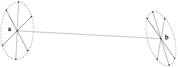
Null vectors in ℝ1,1,1: a 1D couple-wheel pencil; the axis is line ab
-
ℝ0,0,3 (3-space with metric diag(0,0,3)): Its 1D null subspaces represent either all the lines concurrent at the point, called a 2D concurrent pencil of lines, or equivalently, the point of concurrency, or all the lines lying on the same plane, called a 2D coplanar pencil of lines, or equivalently, the supporting plane of the lines. Figure 13.6 shows both cases.
Fig. 13.6 
Null vectors in ℝ0,0,3. Left: a 2D concurrent pencil, or a point. Right: a 2D coplanar pencil, or a plane


We see that in the ℝ3,3 model of line geometry, points and planes are both represented by null 3-blades. Algebraically they cannot be distinguished from each other. We need to introduce an affine structure to make the distinction.
In the Grassmann algebra  over
over  , for an r-blade A
r
and an s-blade B
s
, their 0th-level intersection refers to A
r
∨B
s
. Their ith-level intersection [16] refers to
, for an r-blade A
r
and an s-blade B
s
, their 0th-level intersection refers to A
r
∨B
s
. Their ith-level intersection [16] refers to
if their jth-level intersection is zero for all 0≤j<i. Here (n−s−i,r+s−n+i)⊢A r denotes bipartitioning the r vectors whose outer product equals A r into two subsequences of lengths n−s−i and r+s−n+i, with A r(1) denoting the outer product of the first subsequence, and A r(2) denoting the outer product of the second subsequence. The bracket is set up upon the (n−i)D subspaces spanned by vectors in A r and B s .
Now return to line geometry. Fix a null 3-space of ℝ3,3, and let I
3 be its 3-blade representation. Define the plane at infinity to be the set of lines in space whose representative null vectors are in I
3. A vector  denotes an affine point in 3D affine geometry if and only if for any vector X∈I
3, we have xX≠0 in
denotes an affine point in 3D affine geometry if and only if for any vector X∈I
3, we have xX≠0 in  . Then I
3 introduces a 3D affine structure to the underlying 4D vector space
. Then I
3 introduces a 3D affine structure to the underlying 4D vector space  of 3D projective geometry.
The following properties can be easily established. Let A 3 be a null 3-blade of \(\bigwedge(\mathbb{R}^{3,3})\) linearly independent of I 3.
-
If A 3∨I 3≠0, then A 3 represents an affine point.
-
If A 3∨I 3=0 but A 3∨(1) I 3≠0, then A 3 represents an affine plane.
-
If both A 3∨I 3=0 and A 3∨(1) I 3=0, then A 3 represents a point at infinity.
Let A 3,B 3 be points (including points at infinity), and let \(\mathbf{A}_{3}^{*}, \mathbf{B}_{3}^{*}\) be planes (including the plane at infinity). Then A 3∨(1) B 3 is the line connecting the two points, and \(\mathbf{A}_{3}^{*}\vee^{(1)}\mathbf{B}_{3}^{*}\) is the line of intersection of the two planes. A line represented by null vector X passes through point A 3 if and only if X∧A 3=0; a line X is on plane \(\mathbf{A}_{3}^{*}\) if and only if \(\mathbf{X}\wedge\mathbf{A}_{3}^{*}=0\).
Consider the relationship between a point x=e 0+x 1 e 1+x 2 e 2+x 3 e 3 and a plane passing through a point y=e 0+y 1 e 1+y 2 e 2+y 3 e 3. Without loss of generality, assume that the plane has normal direction e 3. In \(\bigwedge(\mathbb{R}^{3,3})\), the point has the representation
and the plane has the representation
So with respect to pseudoscalar e 01∧e 02∧e 03∧e 12∧e 13∧e 23,
is the squared distance between the point and the plane, or in affine terms, the squared volume of the parallelepiped formed by vectors x−y,e 1,e 2. Similarly, we get
Now fix another null 3-space of ℝ3,3 such that it forms a direct sum decomposition with the plane at infinity I 3. Let J 3 be a null 3-blade representing this 3D null subspace, such that if I 3=E 1∧E 2∧E 3, then \(\mathbf{J}_{3}=-\mathbf{E}_{1}^{*}\wedge\mathbf{E}_{2}^{*}\wedge\mathbf {E}_{3}^{*}\), where \(\mathbf{E}_{i}^{*}\cdot\mathbf{E}_{j}=\delta_{ij}\) for 1≤i,j≤3. The \(\mathbf{E}_{i}^{*}\) are called the reciprocal basis of the E j . Geometrically, J 3 represents an affine point. It is called the origin of the affine space.
For example, let e
0,e
1,e
2,e
3 be a basis of the 3D affine space  such that e
0 represents the origin, and e
1,e
2,e
3 are an orthonormal basis of the plane at infinity. In
such that e
0 represents the origin, and e
1,e
2,e
3 are an orthonormal basis of the plane at infinity. In  , denote
Then in \(\bigwedge(\mathbb{R}^{3,3})\), we can choose
The decomposition
is called a symplectification of ℝ3,3. Let E 1,E 2,E 3 be a basis of I 3, and let \(\mathbf{E}_{1}^{*}, \mathbf{E}_{2}^{*}, \mathbf{E}_{3}^{*}\) be the corresponding reciprocal basis of J 3. Define the symplectic form of the symplectification as

It can be proved that K 2 is invariant under different choices of the basis elements.
Notation
In this section, the duality of \(\mathbf{A}\in\bigwedge(\mathbf{I}_{3})\) in I
3 is denoted by \(\mathbf{A}^{\mathbf{I}_{3}}\); the duality of \(\mathbf{B}\in\bigwedge (\mathbf{J}_{3})\) in J
3 is denoted by \(\mathbf{B}^{\mathbf{J}_{3}}\). The duality of C in  is denoted by C
†.
is denoted by C
†.
Consider a point e 0+x=e 0+x 1 e 1+x 2 e 2+x 3 e 3. Its null 3-blade representation is

where \((\mathbf{e}_{0}\mathbf{x})^{\dagger\mathbf{I}_{3}}\) denotes \(((\mathbf{e}_{0}\mathbf{x})^{\dagger})^{\mathbf{I}_{3}}\). This is a quadratic mapping from ℝ3 to the space of null 3-blades representing affine points.
When x tends to infinity, (13.22) represents a point at infinity. So the point at infinity x has the null 3-blade representation

Consider an affine plane with 2D direction \(\mathbf{L}_{2}\in\bigwedge^{2}(\mathbb{R}^{3})\) and passing through a point x. Its 3-blade representation in  is (e
0+x)L
2. When the plane does not pass through the origin e
0, then xL
2≠0. Rescale L
2 so that the 3-blade representation of the plane in
is (e
0+x)L
2. When the plane does not pass through the origin e
0, then xL
2≠0. Rescale L
2 so that the 3-blade representation of the plane in  becomes

Let L 2=y 1 e 2 e 3−y 2 e 1 e 3+y 3 e 1 e 2. The intersections of plane (13.24) with planes e 0 e 1 e 2, e 0 e 1 e 3, e 0 e 2 e 3 are respectively

So the null 3-blade representation of the plane is

When L 2 tends to infinity, (13.26) represents a plane passing through the origin. So the plane passing through the origin with 2D direction L 2 has the null 3-blade representation

A linear transformation f in  induces another linear transformation \(\underline{f}\) in
  , and the mapping

is a group monomorphism. Let A
1,A
2,…,A
6 be bivectors in  . They are also vectors in ℝ3,3. Then \([\underline{f}(\mathbf{A}_{1})\underline{f}(\mathbf{A}_{2})\ldots \underline{f}(\mathbf{A}_{6})]=\det(f)^{3} [\mathbf{A}_{1}\mathbf{A}_{2}\ldots\mathbf{A}_{6}]\). So ⊓ is also a group monomorphism from SL(4) to SL(6).
By the definition of the inner product in ℝ3,3, any special linear transformation in  induces a special orthogonal transformation in ℝ3,3. After some mathematical reasoning, it can be proved that ⊓:SL(4)⟶SO(3,3) is a Lie group isomorphism.
Let SL
−(4) be the set of linear transformations in  of determinant −1. Let Sproj(3)=SL(4)∪SL
−(4). Then Sproj(3) is a Lie group. Similarly, let O(3,3)=SO(3,3)∪SO
−(3,3), where SO
−(3,3) are the orthogonal transformations in ℝ3,3 of determinant −1. Both Sproj(3) and O(3,3) have two connected components, and their connected components containing the identity are isomorphic under ⊓. However, any element of SL
−(4) maps points to points, maps planes to planes, but reverses the sign of the inner product in ℝ3,3. On the contrary, any element of SO
−(3,3) keeps the sign of the inner product in ℝ3,3 but interchanges points and planes in space. Thus, (13.28) does not provide an isomorphism between Sproj(3) and O(3,3).
of determinant −1. Let Sproj(3)=SL(4)∪SL
−(4). Then Sproj(3) is a Lie group. Similarly, let O(3,3)=SO(3,3)∪SO
−(3,3), where SO
−(3,3) are the orthogonal transformations in ℝ3,3 of determinant −1. Both Sproj(3) and O(3,3) have two connected components, and their connected components containing the identity are isomorphic under ⊓. However, any element of SL
−(4) maps points to points, maps planes to planes, but reverses the sign of the inner product in ℝ3,3. On the contrary, any element of SO
−(3,3) keeps the sign of the inner product in ℝ3,3 but interchanges points and planes in space. Thus, (13.28) does not provide an isomorphism between Sproj(3) and O(3,3).
Now take a retrospect at the ℝ3,3 model of line geometry. When we identify O(3,3) as the geometric transformation group and check for its action on the null vectors in ℝ3,3, we find that for two linearly dependent null vectors, their relative scale (or ratio) is preserved by O(3,3). Indeed, this scale measures the signed length of the vector representing the direction of the line. A vector with a spatial line as its support is called a spear. In fact, O(3,3) describes the volume-preserving spear geometry in space.
With the spin group representation of the orthogonal transformations, all special projective transformations can be classified by their spinor generators. This chapter has no room left for further discussion.
3 Inverse Singularity Analysis by Wrench Matrix
In screw theory [1], any nonzero vector in ℝ3,3 is called a screw when describing the geometry of lines, called a twist when describing Euclidean motion, and called a wrench in statics. The general form of a nonzero vector in ℝ3,3 is of the form

where s is a unit vector in ℝ3, (s,r×s) are the Plücker coordinates of a line with direction s and passing through point r, and λ,μ are scalars that cannot be zero simultaneously. The scalar h=μ/λ is called the pitch of the screw (or twist, or wrench).
In statics, a force acting on a rigid body is a force wrench F=(f,r×f), where r points to the supporting line of the force. A system of forces acting upon a rigid body can be described by a wrench consisting of a certain force and a torque whose supporting plane is perpendicular to the force. If (13.29) represents a wrench, s is the direction of the force in the wrench, and λ is the scale of the force. When λ=0, then h=∞, and the wrench is the sum of two forces of the same magnitude but of opposite direction. Its action leads to a rotation about an axis along the direction of f. Such a wrench is called a pure torque. When h=0, the wrench is a pure force.
An infinitesimal Euclidean motion in space can be described by a vector in the Lie algebra of the 3D Euclidean group, say 6D vector \(\mathbf{S}=(\mathbf{s}, \bar{\mathbf{s}}+\mathbf{t})\), where \((\mathbf{s}, \bar{\mathbf{s}})\) is a spear on the axis of the infinitesimal rotation and generating the latter, and t is a vector generating the infinitesimal translation. By Charles’ theorem, s and t are linearly dependent for any infinitesimal Euclidean motion.
A rigid body is said to receive a twist about a screw if it rotates uniformly about the screw, and at the same time translates uniformly along the screw through a distance equal to the product of the pitch and the angle of rotation. If (13.29) represents a twist, then s is the direction of the rotation axis, r points to the axis, λ is the angle of rotation, and μ is the distance of translation.
In (13.29), when λ=0, then h=∞, and the motion is a pure translation along the axis. When μ=0, the twist reduces to a pure rotation around the axis. A twist generating an infinitesimal motion is called an infinitesimal motion twist or velocity twist.
The virtual work done by a wrench W to a twist S is their inner product in ℝ3,3. A wrench and a twist are said to be reciprocal to each other if they have zero virtual work. If the work done by a wrench of a mechanism to a velocity twist is zero, the wrench is called a constraint of the mechanism. If a wrench is reciprocal to all twists of a mechanism, it is called a common constraint of the mechanism.
The ℝ3,3 model of line geometry provides vector representation to the driving wrenches of 1-dof kinematic pairs such as revolute pairs, prismatic pairs, and screw pairs. It provides bivector representation to the driving wrenches of 2-dof kinematic pairs such as cylindrical pairs.
In ℝ3,3, the common constraints are the orthogonal complement of the kinematic screw (twist) system of a mechanism [8, 9, 19]. Figure 13.7 is a typical example of a limb used in parallel manipulators. It has a stretchable length L, and its two ends are ball joints. Let e 1,e 2,e 3 be an orthonormal basis of the space such that e 3 is along the limb. The kinematic screw system of the limb is composed of the following, where 0 denotes the zero vector in ℝ3:
-
1.
The three infinitesimal rotation generators of the base ball joint:
 (13.30)
 -
2.
The infinitesimal translation generator along the shaft of the limb:
 (13.31)
 -
3.
The three infinitesimal rotation generators of the moving ball joint:
 (13.32)


Since the above seven vectors span ℝ3,3, their orthogonal complement is zero, and the limb does not have any common constraint.

Left: a limb of stretchable length L with two ball joints. Right: the 7 twists of the limb
Traditionally, inverse singularities of a Stewart platform are defined to be the singularities of the Jacobian mapping the velocity of the end-effector to the joint velocities. In [6], it is shown that the columns of the Jacobian matrix are zero-pitch or infinite-pitch wrenches (i.e., pure forces or pure torques) acting upon the moving platform. The inverse singularities can thus be interpreted as configurations where the lines of actions are linearly dependent [7].
By (13.30) to (13.32), for a Stewart platform, in the course of motion there does not occur any common constraint. For a GSP, however, things are quite different. Figure 13.8 is a GSP limb connecting two lines where either the distance L or the angle θ between the two lines is used to drive the mechanism. Let e 1,e 2,e 3 be an orthonormal basis where e 2 is along the lower revolute joint axis, and e 3 is along the shaft of the limb. Let the direction of the upper revolute joint axis be \(\mathbf{e}_{4}=(\cos\theta, \sin\theta, 0)\). The kinematic screw system of the limb is composed of the following:
-
1.
The infinitesimal rotation generator and translation generator of the base revolute joint:
 (13.33)
 -
2.
The infinitesimal rotation generator and translation generator of the limb shaft:
 (13.34)
 -
3.
The infinitesimal rotation generator and translation generator of the upper revolute joint:
 (13.35)
where \(\mathbf{e}_{5}=\mathbf{e}_{3}\times\mathbf{e}_{4}=(-\sin\theta,\cos\theta,0)\).


Left: a limb of stretchable length L and variable angle θ between two revolute joint axes. Right: the 6 twists of the limb
When \(\cos\theta=0\), i.e., the two revolute joint axes are parallel to each other, then e 4=±e 2 and e 5=∓e 1. So (e 1,0)T is not spanned by the above six vectors in ℝ3,3; since (0,e 1)T spans the orthogonal complement of them, it is the common constraint of the limb. It is a pure torque that should result in a virtual rotation of some part of the limb around an axis in the direction of e 1 but fails to make it due to the perpendicularity of the whole structure to e 1.
The occurrence of common constraints can compensate for the linear degeneracy of driving wrenches to make a configuration nonsingular. If we stick to the original Jacobian map from the velocity of the end-effector to the joint velocities, we get wrong conclusions on the singularity of the configuration. For a GSP, we need to consider the following more general Jacobian map  .
.
In a parallel manipulator, let there be all together n driving wrenches and linearly independent common constraint wrenches. For a GSP, n≥6. Each driving wrench P i when executed leads to a virtual displacement q i along the wrench. Let the end-effector velocity be denoted by vector X #∈ℝ3,3, where “#” is the linear transformation in ℝ3,3 changing X=(x,y) to (y,x) for any x,y∈ℝ3. Let

where the n−6 zeroes denote the virtual displacements of the n−6 linearly independent common constraints. Now the parallel manipulator is in singular configuration if and only if the following matrix  defined for arbitrary X is of rank less than 6:

Below we prove that  can be represented by the matrix of driving wrenches and common constraint wrenches. This conclusion holds not only for GSPs, but for all parallel robots of at most 6 degrees of freedom.
Each driving wrench or common constraint wrench is a vector P i in ℝ3,3. The wrench matrix of the system refers to the following 6×n matrix:

In a force statical equilibrium of the end-effector, the external force and torque wrench E equals the sum of the driving wrenches and common constraint wrenches:

where  is an nD vector whose components are the force scales of the driving wrenches and common constraint wrenches.
The virtual work done by E equals the virtual work done by  , so
, so

where the dot symbol denotes the inner product in ℝ3,3. By (13.37), (13.39), and (13.40),  for arbitrary
  and δ
X; hence
and δ
X; hence

A GSP is in singular configuration if and only if its driving wrenches and constraint wrenches span a linear subspace of dimension less than 6.
4 Singular Configurations of GSPs
According to the driving parameters of a GSP, all GSPs can be divided into four classes: (1) 3D3A: 3 distance control parameters and 3 angle control parameters, (2) 4D2A, (3) 5D1A, (4) 6D. There cannot be more than three angle control parameters due to the fact that a rigid body needs at most three angle constraints to determine its orientation.
Figure 13.9 illustrates a limb of fixed length L and driven by line/plane angle θ. Let e 3 be along the shaft, and e 2 be normal to the plane. The upper revolute line is in direction \(\mathbf{e}_{4}=(\cos\theta, \sin\theta, 0)\). Let \(\mathbf{e}_{5}=(-\sin\theta, \cos\theta,0)\). The kinematic screw system of the limb is the following:
-
1.
The infinitesimal translation generators of the base plate:
 (13.42)
 -
2.
The infinitesimal rotation generator of the limb shaft:
 (13.43)
 -
3.
The infinitesimal translation generator and rotation generator of the upper revolute axis:
 (13.44)


The above five twists span a 5D subspace of ℝ3,3 when \(\sin\theta\neq0\), i.e., when the upper revolute axis is not parallel to the base plate. Its 1D orthogonal complement is spanned by a vector (0,e 5)T, which represents the common constraint of the limb. When θ=0 mod π, the orthogonal complement is 2D, and is spanned by vectors (0,e 2)T and (e 2,−L e 1)T.

A limb driven by line/plane angle
Figure 13.10 shows a limb of fixed length L and driven by plane/plane angle θ. Let e 3 be along the limb shaft, and e 2 be normal to the plane. Let \(\mathbf{e}_{4}=(\cos\theta, \sin\theta, 0)^{T}\). The kinematic screw system of the limb is the following:
-
1.
The infinitesimal translation generators of the base plate:
 (13.45)
 -
2.
The infinitesimal rotation generator of the limb shaft:
 (13.46)
 -
3.
The infinitesimal translation generators of the upper plate:
 (13.47)


When \(\sin\theta\neq0\), i.e., when the two plates are not parallel to each other, then the above five twists span a 4D subspace of ℝ3,3, whose 2D orthogonal complement is spanned by vectors (0,e 1)T and (0,e 2)T, which represent two linearly independent common constraints of the limb. When the two plates are parallel, the twists span a 3D subspace, whose 3D orthogonal complement has a third vector generator (e 2,0)T.

A limb driven by plane/plane angle
We have computed the common constraints of all the limbs used in GSPs, four of which have been shown in this chapter so far. The following list summarizes the number of linearly independent common constraint wrenches of a limb in GSP:
- #=0:
-
(1) point to point (or point to line, or point to plane) distance drive; (2) non-parallel line/line distance or angle drive.
- #=1:
-
(1) line to parallel line distance or angle drive; (2) line to plane distance drive; (3) line to nonparallel plane angle drive.
In the above three cases, the common constraint wrench is a null vector in ℝ3,3 representing a pure torque.
- #=2:
-
(1) line to parallel plane angle drive; (2) plane/plane distance drive; (3) non-parallel plane/plane angle drive.
In the first case, the common constraint wrenches form a 2D subspace ℝ1,1 in ℝ3,3, whose two null 1-subspaces represent a pure force and a pure torque, respectively. In the latter two cases, the common constraint wrenches form a 2D null subspace whose null 1-subspaces represent pure torques.
- #=3:
-
parallel plane/plane angle drive.
In this case, the common constraint wrenches form a 3D subspace ℝ1,1,1 in ℝ3,3, where the unique null 1-subspace orthogonal to the whole ℝ1,1,1 represents a pure force, and the two null 2-subspaces both represent pure torques.
Below consider the 5D1A-type GSP shown in Fig. 13.11. It is actuated by five distance constraints between point pairs and one angle constraint between two lines. There are only three ball joints linking the moving platform: B 1,2,B 3,4, and B 5. Lines B 1,2 B 3,4 and A 2 A 3 are connected by a revolute limb S of stretchable length. This GSP has the following kinds of singularities:

A 5D1A-type GSP
Singularity type 1
The five lines supporting the driving wrenches of the limbs between point pairs are linearly independent, while the driving wrench and possible common constraint wrench of the limb S between two lines are both within the 5D subspace spanned by the five lines.
Figure 13.12 shows such a singular configuration. Line A 5 B 5 meets line B 1,2 B 3,4, and lines A 2 A 3∥B 1,2 B 3,4. The five limbs between point pairs all have their supporting lines intersecting line B 1,2 B 3,4 but are otherwise arbitrary, so they form a 5D subspace of ℝ3,3 with degenerate inner product.

A configuration of singularity type 1
Let e 1 be along B 1,2 B 3,4, and e 2 be along S. Let B 1,2 be the origin of the coordinate system. Now limb S has a driving torque (0,e 2)T and a common constraint wrench (0,e 3)T, and both are orthogonal to (e 1,0)T, i.e., both when taken as lines intersect line B 1,2 B 3,4. So all seven wrenches have their supporting lines intersecting a common line, i.e., their representative null vectors orthogonal to the same null vector in ℝ3,3. Hence the configuration is singular.
Singularity type 2
The five lines between point pairs are linearly dependent, and the two lines connected by the angle-driven limb S are not parallel.
Singularity type 3
The five lines between point pairs span a 4D linear subspace, the two lines of limb S are parallel, and the 4D subspace has nonempty intersection with the 2D subspace spanned by the driving wrench and common constraint wrench of limb S.
Figure 13.13 shows such a singular configuration. All points except for B 5 lie in the same plane, and A 2 A 3∥B 1,2 B 3,4. Since lines A 1 B 1,2, A 2 B 1,2, A 3 B 3,4, A 4 B 3,4 are in the same plane, and the line at infinity of the plane supports the common constraint wrench of S, the rank of the five lines is 3, and the rank of the 6×7 wrench matrix is 5.

A configuration of singularity type 3
Singularity 4
The five lines between point pairs span a linear subspace of dimension at most 3.
Figure 13.14 shows another type of 5D1A GSP in a configuration where the matrix of driving wrenches is singular but the whole wrench matrix is not, and hence the configuration is nonsingular.

A nonsingular configuration whose matrix of driving wrenches is singular
In the configuration, lines A 5 B 5, A 2 B 1,2, A 3 B 3, A 4 B 4 intersect at the same point O, and A 3 A 4∥B 3 B 4. Let e 1 be along B 3 B 4, and e 2 be along the shaft of the limb S connecting two lines. Let O be the origin of the coordinate system. Then limb S has a driving torque (0,e 2)T and a common constraint wrench (0,e 3)T, and limbs A 5 B 5, A 2 B 1,2, A 3 B 3, A 4 B 4 span a null 3-space of ℝ3,3 with basis (e 1,0)T, (e 2,0)T, and (e 3,0)T. So to limb A 1 B 1,2, let s be its direction, and let r be the vector from O to B 1,2. Then as long as the three vectors r,s,e 1 are linearly independent, the wrench matrix is nonsingular. On the contrary, the matrix of driving wrenches is always singular.
5 Conclusion
The ℝ3,3 model of line geometry is ideal for analyzing line complexes and designing line-based surfaces. Spinor representation of 3D special projective transformations casts new light on geometric construction and decomposition of projective transformations. This model thus carries the hope of many GAers in improving the performance of GA in projective geometry.
6 Exercises
13.1
Investigate which lines are represented by the nonline element E=e 03∧e 12 in ℝ3,3 if the original 3D space is Euclidean. Probe with L=(e 0+d)u (where d⋅u=0) in two ways, related dually: solve L⋅E=0, and solve L∧E=0.
13.2
(Continued from previous): You should have found e 3⋅(u(1∓d ∗)), where ∗ denotes the dual in the 3D space. Interpret these sets of lines geometrically.
13.3
Following the hints at the end of Sect. 13.2, show that \(\exp(\frac{1}{2}\tau e_{12} \wedge e_{31})\) represents the translation versor for a translation over τe 1.
13.4
Following the hints at the end of Sect. 13.2, show that \(\exp(\frac{1}{2}\gamma e_{01} \wedge e_{23})\) represents the scaling versor for a scaling relative to the origin by e γ along the e 1-direction.
13.5
(Continued from previous): Provide versors for the remaining projective transformations.
Notes
- 1.
Editorial note: See also Chap. 14.
References
Ball, R.: The Theory of Screws: A Study in the Dynamics of a Rigid Body. Hodges, Foster (1876)
Basu, D., Ghosal, A.: Singularity analysis of platform-type multi-loop spatial mechanism. Mech. Mach. Theory 32, 375–389 (1997)
Ben-Horin, P., Shoham, M.: Singularity analysis of a class of parallel robots based on Grassmann–Cayley algebra. Mech. Mach. Theory 41, 958–970 (2006)
Busemann, H.: Projective Geometry and Projective Metrics. Academic Press, New York (1953)
Cayley, A.: On the six coordinates of a line. Trans. Camb. Philos. Soc. 5, 290–323 (1869)
Collins, C., Long, G.: Singularity analysis of an in-parallel hand controller for force-reflected teleoperation. IEEE J. Robot. Autom. 11, 661–669 (1995)
Dandurand, A.: The rigidity of compound spatial grids. Struct. Topol. 10, 41–56 (1984)
Fang, Y., Tsai, L.: Structure synthesis of a class of 4-DoF and 5-DoF parallel manipulators with identical limb structures. Int. J. Robot. Res. 21, 799–810 (2002)
Featherstone, R.: Robot Dynamics Algorithms. Springer, Berlin (1987)
Gao, X., Lei, D., Liao, Q., Zhang, G.: Generalized Stewart–Gough platforms and their direct kinematics. IEEE Trans. Robot. Autom. 21, 141–151 (2005)
Gosselin, C., Angeles, J.: Singularity analysis of closed-loop kinematic chains. IEEE Trans. Robot. Autom. 6, 281–290 (1990)
Hodge, W., Pedoe, D.: Methods of Algebraic Geometry, vol. 1. Cambridge University Press, Cambridge (1952)
Huang, Z., Chen, L., Li, W.: The singularity principle and property of Stewart parallel manipulator. J. Robot. Syst. 20, 163–176 (2003)
Hunt, K.: Kinematic Geometry of Mechanisms. Oxford University Press, Oxford (1978)
Jenner, W.: Rudiments of Algebraic Geometry. Oxford University Press, Oxford (1963)
Li, H.: Invariant Algebras and Geometric Reasoning. World Scientific, Singapore (2008)
Long, G.: Use of the cylindroid for the singularity analysis of rank 3 robot manipulator. Mech. Mach. Theory 32, 391–404 (1997)
Maxwell, E.: General Homogeneous Coordinates in Spaces of Three Dimensions. Cambridge University Press, Cambridge (1951)
Merlet, J.: Singular configurations of parallel manipulators and Grassmann geometry. Int. J. Robot. Res. 8, 45–56 (1989)
Merlet, J.: Parallel Robots. 2nd edn. Springer, Heidelberg (2006)
Park, F., Kim, J.: Singularity analysis of closed kinematics chains. J. Mech. Des. 121, 32–38 (1999)
Pottmann, H.: Computational Line Geometry. Springer, Heidelberg (2001)
Semple, J., Roth, L.: Introduction to Algebraic Geometry. Oxford University Press, Oxford (1949)
Sommerville, D.: Analytic Geometry of Three Dimensions. Cambridge University Press, Cambridge (1934)
Stewart, D.: A platform with six degrees of freedom. Proc. Inst. Mech. Eng. 180, 371–378 (1965)
Study, E.: Geometrie der Dynamen. Leipzig (1903)
Woo, L., Freudenstein, F.: Application of line geometry to theoretical kinematics and the kinematic analysis of mechanical systems. J. Mech. 5, 417–460 (1970)
Yang, A.: Calculus of screws. In: Spillers, W. (ed.) Basic Questions of Design Theory. Elsevier, Amsterdam (1974)
Zlatanov, D., Fenton, R., Benhabib, B.: Identification and classification of the singular configurations of mechanisms. Mech. Mach. Theory 33, 743–760 (1998)
Author information
Authors and Affiliations
Corresponding author
Editor information
Editors and Affiliations
Rights and permissions
Copyright information
© 2011 Springer-Verlag London Limited
About this chapter
Cite this chapter
Li, H., Zhang, L. (2011). Line Geometry in Terms of the Null Geometric Algebra over ℝ3,3, and Application to the Inverse Singularity Analysis of Generalized Stewart Platforms. In: Dorst, L., Lasenby, J. (eds) Guide to Geometric Algebra in Practice. Springer, London. https://doi.org/10.1007/978-0-85729-811-9_13
Download citation
DOI: https://doi.org/10.1007/978-0-85729-811-9_13
Publisher Name: Springer, London
Print ISBN: 978-0-85729-810-2
Online ISBN: 978-0-85729-811-9
eBook Packages: Computer ScienceComputer Science (R0)