
Abstract
The effective management of reactive power plays a vital role in the operation of power systems, impacting voltage stability, power quality, and energy transmission efficiency. Despite its significance, suboptimal reactive power planning (RPP) can lead to voltage instability, increased losses, and grid capacity constraints, posing risks to equipment and system reliability. Rigorous RPP methodologies can mitigate these challenges, resulting in tangible improvements in voltage profiles, system stability, and reduced losses. A comprehensive review of 20 technical articles published between 2020 and 2023 was conducted to compare and synthesize contributions to the field of RPP. The review highlighted the efficacy of strategic RPP approaches in reducing power losses, minimizing equipment malfunctions, and improving power quality, leading to substantial economic benefits—strategic planning approaches and integrating emerging technologies. For instance, examples include renewable energy sources and energy storage systems, which offer promising avenues for enhancing RPP and ensuring stability, reliability, and efficiency in power systems.
Introduction
Reactive power planning is pivotal in power system functionality, profoundly influencing voltage stability, power quality, and energy transmission efficiency. However, the repercussions of suboptimal or erroneous planning in this domain can cascade into a series of detrimental impacts, significantly compromising the robustness and efficacy of the entire system.
A primary consequence of inadequacies in reactive power planning surfaces is voltage instability, characterized by deviations in voltage levels surpassing permissible thresholds, resulting in voltage sags, fluctuations, and collapses. Studies demonstrate that accurate reactive power management can amplify the Voltage Stability Index (VSI) by ~ 40%, manifesting tangible improvements in voltage profiles and system stability (Manohara and Veera Reddy 2023a). Furthermore, suboptimal planning disrupts the delicate equilibrium between active and reactive power, leading to escalated resistive losses in transmission and distribution systems.
Rigorous reactive power planning (RPP) methodologies showcase the capacity to curtail power losses by a noteworthy range, from a 53% reduction to a mere 14% when juxtaposed with scenarios devoid of strategic planning (Borgatti et al. 2020). Grid capacity, a requirement for the effective transmission of active power within a power system, suffers under the weight of inadequate reactive power support. This limitation affects obstruction and diminishes the capacity to cater to escalating power demands, which, in specific scenarios, necessitates costly grid expansion initiatives (Zhang and Tolbert 2005).
The repercussions extend to the realm of equipment, where suboptimal reactive power management exposes electrical components to undue stress, inducing overheating, curtailed lifespan, and an augmented risk of equipment failures. Reactive power planning is pivotal in mitigating transmission losses and operating costs and elevating voltage profiles, resulting in notable loss reductions of up to 25.82%.(Ela et al. 2011)
Beyond these technical quandaries, suboptimal planning exacts its toll on power quality, precipitating heightened harmonic distortions and a compromised power factor (Aoki et al. 1988). These power quality deficiencies harbour the potential to disrupt sensitive equipment, imperilling performance and reliability (Mantovani and Garcia 1996). Voltage dips, constituting ~ 31% of disturbances, emerge as a prevalent disruption resulting from flawed reactive power planning (Kaloudas et al. 2017).
Moreover, the economic fallout of suboptimal planning is profound, manifesting as amplified power losses, equipment malfunctions, and power quality issues, culminating in escalated operational expenditures for utility entities and industrial stakeholders (Anaya and Pollitt 2020). Studies advocate for the efficacy of proposed methods, such as the exclusive deployment of capacitor banks or hybrid approaches, showcasing noteworthy net savings ranging from 18.25% to 25.82%, underscoring the economic imperatives of careful reactive power planning (Surani 2018a).
Many researchers focus on reactive power planning in traditional power systems, emphasizing efficient management and control of reactive power to maintain voltage stability and ensure reliable operation (Surani 2018b). This traditional approach optimizes reactive power sources to balance supply and demand, primarily around conventional generation units and their associated reactive power capabilities (Garg et al. 2016). Various techniques, such as optimal power flow analysis and voltage stability assessment, are employed to determine the optimal allocation and control of reactive power devices (Shaw et al. 2014), ensuring the smooth operation of electrical networks.
Reactive power planning in microgrids has witnessed significant advancements, so managing reactive power to ensure voltage stability has become crucial, mainly due to the rise in renewable energy sources and the utilization of distributed generators (DGs) (Tom and Scaria 2013a). Microgrids, which are localized power systems that can function autonomously or in conjunction with the primary grid, are increasingly being implemented and feature renewable energy generation, energy storage systems, and smart grid technologies (Pudjianto et al. 2002). Characterized by the persistent penetration of renewable energy sources, it introduces a unique layer of complexity to reactive power planning management (Karmakar 2021). The ensuing sections will delve into these intricacies, providing insights into the challenges, potential strategies, and future perspectives within the evolving landscape of microgrids.
As microgrids evolve, new challenges and research areas emerge in reactive power planning. One key aspect is the integration of the complex dynamics of microgrids, which involve the integration of various renewable energy sources like solar photovoltaic (PV) panels and wind turbines (Uniyala and Kumar 2018), which have intermittent and fluctuating power output. The goal is to balance the reactive power requirements of these renewable sources. Another important aspect is the utilization of energy storage systems (ESS) (Zhang et al. 2007) and emerging technologies like electric vehicles (EVs) with bidirectional power flow capabilities (Roy et al. 2013). Energy storage systems (ESS) are vital in mitigating the intermittent characteristics of renewable energy sources and offering reactive power assistance as necessary. They can inject or absorb reactive power, ensuring voltage stability and compensating for imbalances within microgrids.
Integrating smart grid technologies and communication systems enables the real-time supervision and regulation of reactive power assets. This facilitates effective coordination and optimization of reactive power sources alongside renewable energy resources and ESS, guaranteeing optimal voltage profiles and power quality. Furthermore, advanced control algorithms aim to optimize the coordination of reactive power and explore innovative energy management strategies that concurrently address active and reactive power considerations.
Reactive power is reviewed by many studies from different points of view, such as reactive power management (Gopalakrishnan et al. 2004), traditional voltage and reactive power control (Garg et al. 2016), and reactive compensation devices' thermal limits and operating constraints (Ponce 2015). Unlike previous studies, this article focuses on the reactive power planning of microgrids with non-conventional reactive power dynamics, causing the high penetration of renewable energy resources. So, the RPP problem aims to determine ‘‘where” and ‘‘how many” new VAR compensators must be added to a network for a predefined horizon of planning at minimum cost while satisfying an adequate voltage profile during normal conditions and contingencies.
After this introduction, the market for reactive power offers a platform to trade and manage the supply and demand of reactive power within the electricity grid, which is explored in "The market for reactive power", where the pricing scheme of the market is discussed. "Reactive power dynamics" focuses on understanding and managing reactive power dynamics to ensure the stability and reliability of electricity grids. "Reactive power modeling" describes how the system configuration and operational considerations of reactive power modelling have been. Previous studies on reactive power planning (RPP), including optimization techniques, technical/economic objective functions, reactive compensation devices, cost analysis of VAR sources, and the capabilities of inverters in providing reactive power, are discussed in "Previous studies". "Conclusion and future perspectives" identifies the research gaps discovered in the previous RPP studies. Lastly, in Sect. 6, the article highlights the main conclusions and contributions made, as shown in Fig. 1.

Article graphical framework
The market for reactive power
The market for reactive power has evolved significantly, driven by shifts in the energy landscape and technological advancements. Capacity markets have emerged to address challenges in procuring reactive power capacity, offering fixed payments instead of variable ones based on produced VAR hours. Studies, including (Weber et al. 1998; EWEA 2009), propose Optimal Power Flow (OPF)-based methods, with a suggestion to adopt capacity payments to stimulate investment due to price volatility. Historical data reveals the enduring value of fixed payments as a transitional mechanism. However, a growing consensus is that fixed costs need to be updated. Diverse pricing structures influenced by location, regulatory policies, and power system requirements have emerged, as outlined in Table 1 (Commission and Order 2222).
DGs contribute 42% of the US grid's reactive power support, even at power factors as low as 0.6, as discussed in Potter et al. (2022). The reactive power market provides DGs with a critical platform to actively support reactive power and generate additional revenue streams from the reactive power market, which can contribute up to 10% of the total revenue for market participants. DGs leverage incentives within the market, sourcing over 10% of their income while operating at lower power factors (Haider et al. 2020). This coordinated resource utilization, facilitated by the market framework, enhances network voltages, demonstrating a significant 2.2% increase in average voltage levels compared to scenarios with minimal DGs integration (NERCNerc 2010; Haider et al. 2021). The inherent stability of daily reactive power supply contributes to reduced pricing volatility, ensuring consistent and reliable revenue streams (Zhou et al. 2018). This stability enhances the credibility of the reactive power market, attracting increased DGs participation within the retail sector and influencing strategic investment decisions related to further DGs integration and adoption (FERC Standard (LGIA) 2005).
Reactive power dynamics
Reactive power planning in power systems traditionally relies on synchronous generators, which produce a rotating magnetic field, and requirements are based on synchronous field considerations (Ellis et al. 2012). Generators strive to optimize their operations and regulate voltage and power factors. Power systems typically require a power factor to be maintained within a range of 0.95, leading to 0.95 lagging. However, this requirement only applies to wind generators if their output exceeds 10% of the facility's capacity (Standard and FAC-001-0 2005).
Non-synchronous generators must meet power factor criteria only when their output surpasses 10% of the facility's capacity (IEEE 2018; Barquin Gil et al. 2000). On the other hand, synchronous machines must possess a capability curve that allows them to supply a lagging power factor or absorb a leading power factor.
Distributed generators (DGs) have a minimal impact on grid voltage support when their penetration is low. However, with high penetration, they can cause oscillations and voltage fluctuations (Marzo et al. 2022).
The IEEE 1547-2018 standard highlights the active involvement of different DG units in enhancing grid voltage stability (Zhang et al. 2010; Rahmouni et al. 2020). Each unit is expected to contribute reactive power up to 44% of its rated capacity, as specified by the voltage-reactive power curve.
DGs are categorized into four types based on their power capabilities: Type 1 includes active power-only producers like photovoltaic systems, Type 2 comprises traditional generators that produce both active and reactive power, and Type 3 consists of exclusive providers of reactive power, such as synchronous compensators), and Type 4 (induction generators that consume and produce reactive power) (Lee 2011).
As microgrids increasingly incorporate renewable energy sources with variable generation, reactive power compensators help mitigate voltage fluctuations and power imbalances. In autonomous or grid-connected microgrids, using reactive power compensators is essential for creating a resilient and responsive energy infrastructure capable of adapting to varying load conditions and maximizing the efficiency of renewable energy integration (Joseph et al. 2020). This will be discussed in the following section.
Reactive power modeling
In recent years, both PV and wind systems, especially Doubly Fed Induction Generator (DFIG) systems have played a crucial role in supporting the grid's reactive power requirements. The specific control strategies and models may vary depending on the system design, control algorithms, and grid requirements. These models are continuously evolving to improve the integration of renewable energy sources into the grid and ensure grid stability and reliability.
PV systems model
PV systems are primarily designed to generate active power from solar energy. However, they can also contribute to the grid's reactive power requirements. The reactive power output of a PV system depends on the type of inverter used. PV inverter not only can inject active power into the grid but also can control the reactive power injected/absorbed acting on control voltage, Vg in the Point of Common Coupling (PCC). Applying the equations for the three-phase voltages may be expressed by (1, 2 and 3), proposed by Albarracín and Alonso (2013).
Being da, db, and dc the duty cycles on PV inverter phases a, b and c, respectively. From (1), equations for abc can be rewritten to dq coordinates (2) and (3), by using Park transformation (Tom and Scaria 2013a), as follows:
where: Vid and Viq are inverter voltages in dq coordinates, respectively. Being Vi = Vdc. d, the inverter voltage, which is the DC voltage input multiplied by its duty cycle.
PV inverter capacity
Optimizing the capacity of reactive power in PV sources is essential for the efficient and effective operation of solar power systems and their integration into the larger electrical grid.so, Having an adequate capacity of reactive power in PV sources is crucial for maintaining grid stability (Tom and Scaria 2013b; Prathap et al. 2011), especially when PV systems are connected to the utility grid. It also helps in mitigating voltage fluctuations, reducing line losses, and improving the overall power quality (Ahmed and Strbac 2000).
-
A.
Inverter current limits
The maximum current injected by the PV inverter, denoted as Ii, sets the limits for the active power (P) and reactive power (Q) that can be injected by the PV generator through the PV inverter. These limits are defined by the equation of (5 and 6) as described in Albarracín and Alonso (2013).
$${P}^{2}+ {Q}^{2}={( Vg . Ii )}^{2},$$(5)where Vg is the one-phase voltage in the grid, Ii is the one-phase current in the PV converter, and P-Q represents the active power and reactive power of the network at the PCC, respectively.
From (5) it is possible to write (6) as follows:
$${I}_{i}=\frac{\sqrt{{P}^{2}+{Q}^{2}}}{Vg}.$$(6)The inverter current limits have C2 and r2 which represent the center and radius, expressed in (7) and proposed by Albarracín and Alonso (2013).
$${C}_{2}=\left(\mathrm{0,0}\right); {r}_{2}= {V}_{g } {I}_{i}.$$(7) -
B.
Inverter voltage limits
The restriction is imposed by the maximum voltage of the PV inverter, represented as Vi. This voltage establishes an additional limit on the capacity of active power (P) and reactive power (Q), as described by Eq. (8).
$$Vi= \sqrt{{p}^{2}+{( Q+\frac{{Vg}^{2}}{X})}^{2}} + \frac{Vg}{X}.$$(8)where: The variables Vi and Ii represent the voltage and current, respectively, of the P V inverter for a single phase. Furthermore, the value of Vi is influenced by factors such as the continuous voltage at the inverter input, the modulation technique used, and the rate of amplitude modulation, as mentioned in reference (Chinchilla et al. 2006). The variable X denotes the reactance observed from the terminals of the inverter.
The inverter voltage limit described by Eq. (8) and proposed by Albarracín and Alonso (2013), is an ellipse with the following properties: a (semi-major axis), b (semi-minor axis), c (focal semi-distance), ecc (eccentricity), c1 (centre), and K (constant of the ellipse) the equations may be expressed by (9, 10, 11 and 12) and proposed by IEEE (2018).
$$a=b=\frac{Vg . Vi}{X} ;C=\sqrt{{a}^{2}-{b}^{2}}=0,$$(9)$$ecc= \frac{c}{a}=0 ;0<ecc<1,$$(10)$$c1=\left(0 , -\frac{{Vg}^{2}}{X}\right),$$(11)$$K=2a.$$(12) -
C.
PV active power limits
The maximum achievable active power from the PV field is 1 p.u. Figure 2 depicts the operational limits of a PV inverter, considering all the restrictions collectively. The shaded region represents the feasible operating area of the PV inverter. In the first quadrant, the inverter can inject both active and reactive power, while in the fourth quadrant, it is capable of injecting active power and absorbing reactive power.
Fig. 2 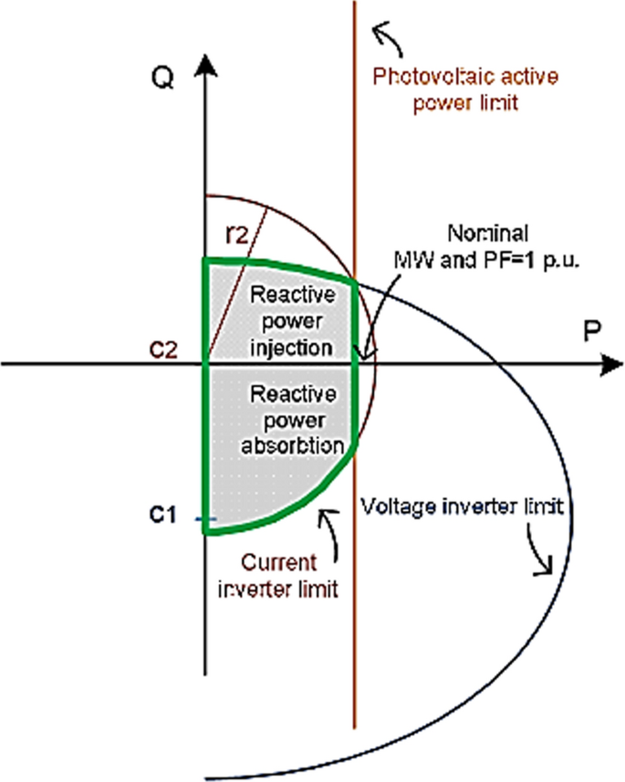
Capacity of active and reactive power in PV generators (Albarracín and Alonso 2013)

DFIG systems model
The wind turbine model is an adaptation of the doubly-fed induction generator (DFIG) described in reference (Eladl et al. 2022; Vale et al. 2010). The DFIG is responsible for converting the mechanical power harnessed by the wind turbine into electrical power. Simultaneously, the DFIG transfers this power to the grid through a back-to-back converter system, consisting of a rotor-side converter and a grid-side converter. The relationship between the input mechanical power Pm and the wind speed is determined by the Betz Eq. (13) and proposed in Eladl et al. (2022).
where: ρ is the air density, R means the radius of the wind turbine, V refers to the wind speed, CP is a value related to blade tip speed ratio λ, and pitch angle, β . which is described in Eq. (14) and can be expressed as in Vale et al. (2010).
where: ωm represents the rotation speed of the wind turbine and in the ideal case.
The active power can be considered as the maximum power point tracking control (MPPT) as prposed in Xu et al. (2022), which is provided as follows in (15).
where: \({P}_{w,base }\) and \({V}_{w,base}\) are the rated output and wind speed of the wind turbine, respectively.
However, the total reactive power fed into the grid is only related to the stator and the grid side converter rather than the rotor. Thus, the total reactive power is given by (16) as proposed in Xu et al. (2022).
where: the reactive power injected into the power grid is bounded by Qgen, max and Qgen, min, representing the upper and lower limits, respectively.
Similarly, the reactive power regulation range for the wind turbine stator side is bounded by Qs, max and Qs, min, while the reactive power regulation range for the grid side converter is bounded by Qc, max and Qc, min. The capacity limits of the DFIG are determined by considering the maximum allowable currents for the stator and rotor, the steady state will denote as rated stator and rotor currents. The total capacity of the generator is obtained by combining the power of the rotor and the stator. As a result, the range of reactive power regulation on the stator side is influenced by the maximum current constraints of both the stator and rotor sides, as illustrated in Eqs. (17, 18 and 19) proposed in Xu et al. (2022).
The upper and lower limits of the reactive power regulation range on the wind turbine stator side, considering the maximum current constraint on the rotor side, are denoted by Qs1, max and Qs1, min, respectively. Similarly, the upper and lower limits of the reactive power regulation range on the wind turbine stator side, considering the maximum current constraint on the stator side, are denoted by Qs2, max and Qs2, min, respectively. Ls represents the stator inductance, while Lm represents the excitation inductance. Ir, max and Is, max represent the maximum current values on the rotor side and stator side, respectively. The rotor slip is denoted by s and ω1 represents the angular velocity of synchronous rotation, and Vs is the stator voltage.
The capacity of the grid side converter sets the limit for the reactive power it can handle, in addition to the transmitted active power expressed in (20) and defined in Chinchilla et al. (2006).
where Sc, max is the capacity of the grid side converter.
A distribution network model incorporating renewable energy sources explained is established to capture the potential for reactive power regulation in different types of networks (Baby and Jayakumar 2020).
Reactive power compensators limits
The reactive power limits of both static and dynamic compensators are subject to variation depending on the particular device and its inherent design parameters (Baby et al. 2020; NERC 2009). Below, general equations are outlined concerning reactive power limits for both static and dynamic compensators, emphasizing the necessity to consider specific characteristics and operational parameters in determining these limits (Baby 2019). While the actual limits of specific compensators can vary contingent on their design, control strategies, and system requirements, the following equations provide a foundational understanding (Payasi et al. 2012).
-
a.
Static compensators
Static compensators are characterized by their rated capacity, which dictates the extent of reactive power generation or absorption they can effectively achieve. Exceeding these limits may result in device overload or other operational complications. The reactive power limits for static compensators can be expressed in equation (21) with general form as (Thesis 2022).
$$\left\{\begin{array}{l}{Q}_{max}= {Q}_{rated }\\ {Q}_{min}= - {Q}_{rated}\end{array}\right.,$$(21)where: Qrated is the rated reactive power generated or absorbed by a static compensator and denoted as kVAR (kilovolt-ampere reactive) or MVAR (megavolt-ampere reactive).
-
b.
Dynamic compensators
Dynamic compensators offer greater flexibility and a broader range of reactive power compensation compared to their static counterparts. The reactive power limits for dynamic compensators are predominantly influenced by their control parameters and specific system requirements, rather than fixed ratings .These limits are often tailored to regulate voltage magnitude at the point of connection and maintain it within a specified range, as expressed by Eq. (22) and proposed in Karmakar and Bhattacharyya (2023).
$$\left\{\begin{array}{c}{Q}_{max}=\left( {V}_{max}-{V}_{nom} \right) {I}_{base}\\ {Q}_{min}=\left( {V}_{min}-{V}_{nom} \right) {I}_{base}\end{array}\right.,$$(22)where: Vmax and Vmin are the maximum and minimum allowable voltage magnitudes, Vnom is the nominal voltage, and Ibase is the system base current.
Additionally, dynamic compensators may have reactive power limits established to ensure system stability, which are determined based on stability criteria and can vary according to specific system dynamics (Anand and Balaji 2015)). It's important to note that these equations represent a general form, and further details regarding specific compensator types and their reactive power characteristics will be discussed comprehensively in "Reactive power compensators", drawing upon previous studies and relevant literature.
These considerations underscore the importance of understanding the reactive power limits and characteristics of compensators, as they play a critical role in maintaining power system stability and efficiency (Mahdad 2019).
Previous studies
In this study, we employed a rigorous methodology to select and review literature on RPP to ensure the credibility and comprehensiveness of our analysis. Our selection criteria focused on identifying twenty papers published in prestigious, well-indexed journals renowned for their contributions to the field of power systems. To promote diversity of perspectives and minimize bias, we excluded repeated studies with minimal differences in assumptions or methodologies. This approach enabled us to capture a broad spectrum of insights and methodologies while prioritizing papers offering unique contributions to advancing RPP knowledge. Additionally, we conducted a thorough review and synthesis of the selected literature to extract key findings, trends, and research gaps in the field. By transparently outlining our methodology, we aim to enhance the credibility and reproducibility of our review process.
Various studies have contributed distinct approaches to reactive power planning, each demonstrating unique features. Exemplary research (Manohara and Veera Reddy 2023b) focusing on multi-objective reactive power planning emphasizing renewable energy integration introduces a comprehensive optimization model employing the Northern Goshawk optimization technique. While adeptly optimizing losses, voltage stability margins, and reducing greenhouse gas emissions, a notable limitation arises in neglecting system cost considerations. Another study on active distribution networks utilizing multi-agent reinforcement learning (Eladl et al. 2023; Gupta and Babu 2022) integrates a modified fuzzy min-max technique with the Genetics algorithm (MOGA). The precise objectives include maximizing the voltage stability margin and minimizing the cost of new VAR sources. Yet, a gap persists as the study needs to present information on system power losses (Shojaei et al. 2021).
In a study deploying a hybrid optimization algorithm for power systems with high renewable energy penetration (Faraji et al. 2021), combining each Mixed Integer Non-linear Programming, Hybrid Krill-Herd optimization, and Crow algorithm, the objectives revolve around minimizing total planning cost instead of energy not supplied then voltage security index. However, critical consideration of system losses must be addressed, introducing a trade-off in the optimization framework. In the context of reactive power planning in distribution networks using chance-constrained optimization (Roy et al. 2023), the model employs the Gravitational Search Algorithm for PVs with shunt capacitors (SCs). The study targets losses, voltage profile improvement, and carbon emission reduction. They are yet, echoing prior studies, a notable gap surfaces in consideration of the total cost of PVs, underscoring the imperative for a holistic evaluation of the proposed optimization model.
These studies employ diverse optimization techniques, including Northern Goshawk Optimization, Genetics algorithm, Hybrid Krill Herd Optimization, and Gravitational Search Algorithm. Their shared objective is optimizing reactive power planning, minimizing losses, enhancing voltage stability, and integrating renewable energy sources. However, the inconsistency in addressing systems costs and losses underscores the need for a standardized and comprehensive approach to reactive power planning that considers economic and technical aspects. Moreover, uncertainties associated with renewable energy integration and system parameters necessitate more consistent attention to enhance the robustness of the reactive power planning strategies in the face of evolving power system dynamics.
The main features of the examined documents are summarized in Table 2. These chosen articles significantly augment the depth of knowledge within the specified field, offering valuable information and research outcomes specific to this time frame. The comparative analysis delves into various aspects, including the types of studied reactive power compensators, cost models, objective functions, optimization techniques, inverter reactive power capability, and considerations about uncertainties, as elucidated in the subsequent subsections.
Reactive power compensators
Reactive power compensation is crucial for preserving power quality, particularly concerning voltage stability. Recent studies have introduced various reactive compensation devices and techniques encompassing capacitor banks. Traditional reactive power provision and power factor enhancement methods have primarily relied on synchronous condenser systems and flexible alternating current transmission systems (FACTS) (Manohara and Veera Reddy 2023b). However, alternative techniques like series/shunt-connected compensators have emerged as more robust solutions for addressing power system instability.
In various microgrid studies, two categories of compensators, namely static and dynamic compensators, have been utilized for reactive power compensation and voltage control. Static compensators, including Static Var Compensators (SVCs) and Thyristors-Controlled Series Capacitors (TCSCs), predominantly operate in a steady-state manner. They continuously adjust voltage and power factors to strengthen system stability (Karmakar and Bhattacharyya 2023). On the other hand, dynamic compensators such as Static Synchronous Compensators (STATCOMs) and Unified Power Flow Controllers (UPFCs) offer a different approach.
Boast enhanced dynamic response capabilities, often integrating energy storage systems or inverters to inject or absorb reactive power in real-time swiftly (Eladl et al. 2023).
Dynamic compensators, with their agility in managing transient conditions, are particularly suited for applications necessitating rapid and precise voltage control, complementing the effectiveness of static compensators in overall system stability and steady-state operation (Shojaei et al. 2021). Among these approaches, FACTS has emerged as a dynamic and efficacious model for voltage stability and regulation, offering benefits such as augmented transmission line capacity and reduced losses (Takahashi et al. 2021). Presently, reactive power compensation devices encompass shunt capacitors, SVCs, and D-STATCOMs, catering to the needs of distribution networks in terms of practicality and economic operation (Eladl et al. 2023).
Researchers often favour STATCOMs and SVCs in distribution systems due to their compact designs and seamless integration into existing infrastructure, thereby enhancing the resilience and flexibility of distribution networks (Belkacem 2021). Table 3 and Fig. 3 delineate commonly employed compensation devices and categorise VAR sources based on their dynamic behaviour. These provide insights into their rapid response capabilities and contributions to sustaining voltage stability during system disturbances (Kaushal et al. 2023).

Studied reactive power compensators
Dynamic sources of reactive power excel in their ability to adapt instantly to system conditions, contrasting with static sources that maintain a fixed capability (Mahapatra and Raj 2023). Consequently, combining various compensation methods, including synchronous condensers, series compensators, capacitor banks, shunt reactors, and SVCs, proves effective for optimizing electric power networks (Gupta and Babu 2022). Despite the multifaceted attributes of reactive power compensators, researchers overlook the intricate dynamics of these devices in microgrid planning, as evidenced in prior studies (Baby and Jayakumar 2020).
Cost analysis
Recent studies have revealed several noteworthy observations regarding reactive power issues in power systems, which are intricately connected to crucial factors such as voltage profile, power losses, power factor and stability. Gaining a comprehensive understanding of the factors that influence system pricing is vital for effective planning and optimization (Ayalew et al. 2019):
-
Anticipated deployment: Predictive models foresee an increased deployment of Reactive Power Compensation installations, significantly contributing to system stability enhancement and blackout prevention. These models account for weather impacts, daily or seasonal variations, and other pertinent factors (Ma et al. 2017).
-
Static Var compensators: Within distribution grids, Static Var compensators exhibit superior control capabilities, potentially reducing the need for investment in transmission lines (Gupta and Babu 2022; Shojaei et al. 2021; Faraji et al. 2021; Roy et al. 2023; Syah et al. 2021; Zhang and Li 2020; Liu et al. 2021; Belkacem 2021; Gupta 2020; Du 2023; Salazar et al. 2022; Takahashi et al. 2021; Kaushal et al. 2023; Muhammad et al. 2021).
-
Cost modeling: Studies emphasize the importance of cost modelling in assessing the economic implications of planning decisions and optimizing the allocation of VAR resources (Eladl et al. 2023; Gupta and Babu 2022; Shojaei et al. 2021; Du 2023). A clear definition of variables, including capital, operating, investment, maintenance, and energy costs, is crucial for formulating concise and mathematical cost models specific to the power system under consideration.
-
Sensitivity analysis: Sensitivity analysis is a valuable tool for evaluating cost models' robustness and ability to handle uncertainties (Belkacem 2021; Gupta 2020).
Investment costs for new VAR sources are derived from a polynomial cost function sourced from the Siemens AG Database (Elazab et al. 2023b). In contrast, annual installation costs are determined based on these investment costs, considering predetermined lifetimes and interest rates (Syah et al. 2021). Strategies aimed at reducing operational expenses, such as combining VAR source installation costs with costs associated with energy losses, are explored, and studies investigate the impact of varying numbers of compensators on annual operating costs, providing insights into the optimal number of devices to install (Pudjianto et al. 2002). Additionally, linear formulations for cost models are proposed to ensure convexity, demonstrating effectiveness in model optimization (Pudjianto et al. 2002). Comprehensive parametric information for compensators, including STATCOMs and D-STATCOM, is available in the literature, facilitating detailed cost analysis and optimization.
Optimization techniques
Mathematical formulations of real-world power system problems are typically developed based on certain assumptions. However, finding solutions for large-scale power systems is more complex, even with these assumptions. Power systems are characterized by their vast size, complexity, and wide geographical distribution, resulting in numerous uncertainties. Additionally, the deregulation of power utilities in recent years has introduced new challenges to the existing problems. Ideally, the solution to power system problems such as RPP should be globally optimal. However, mathematical optimization approaches often yield locally optimal solutions. Consequently, addressing many power system problems solely through strict mathematical formulations becomes challenging.
To address these limitations, artificial intelligence (AI) techniques, including expert systems (ES), artificial neural networks (ANN), genetic algorithms (GA), fuzzy logic, and other methods mentioned in Table 2, have emerged as valuable tools in conjunction with mathematical approaches in power systems. Consequently, numerous research articles have been published on diverse optimization techniques applied to tackle the reactive power planning problem in power systems, as illustrated in Fig. 4.

Studies optimization techniques
Objective functions
Researchers address various objectives in reactive power planning, as follows:
-
I.
Researchers in Eladl et al. (2023) and Zhang and Li (2020) focus on developing optimization models and algorithms to minimize voltage deviations and maintain voltage stability within acceptable limits, optimizing the allocation and operation of reactive power resources.
-
II.
Many researchers concentrate on developing optimization models and methods to allocate reactive power resources, aiming to reduce energy losses in the power system. This objective enhances the efficient utilization of reactive power resources, although some prioritize other objectives over loss minimization, as observed in studies (Gupta 2020; Du 2023; Kaushal et al. 2023).
-
III.
Many researchers aim to enhance the power system stability and optimize allocation and then the operation of reactive power resources. However, this objective may focus solely on improving steady-state stability, omitting consideration for other stability criteria and contingency conditions.
-
IV.
Cost optimization is another focal point for researchers, with objectives to minimize the operational costs of reactive power resources while meeting system requirements. Notable studies in this domain include (Zhang and Li 2020; Liu et al. 2021; Belkacem 2021).
Additionally, operational constraints play a crucial role in reactive power planning. Researchers must consider constraints related to controlling and coordinating reactive power resources. These may encompass limits on the rate of change of reactive power and voltage control zone requirements between control devices. Furthermore, adherence to equipment operating limits, generator capabilities, and thermal limits of transmission lines is essential to ensure stable and reliable power system operation. These considerations collectively contribute to maintaining system stability and reliability.
Uncertainties handling strategies
Researchers employ various strategies to address uncertainties in the reactive power planning (RPP) problem that can be summarized as follows.
-
I.
Incorporating probabilistic models (Faraji et al. 2021; Gupta 2020) involves representing uncertain factors such as load variations, renewable energy generation, and equipment failures. Probability distributions or scenarios are assigned to these variables, and the planning problem is formulated as either a stochastic optimization or robust optimization problem.
-
II.
Scenario-based approaches utilize a set of representative scenarios to capture a range of possible system conditions. These scenarios are used to evaluate RPP strategies. For instance, researchers in Murty and Kumar (2021) analyse solution robustness by considering performance across multiple scenarios and selecting solutions that perform well on average or in worst-case scenarios.
-
III.
Sensitivity analysis (Eladl et al. 2023; Shojaei et al. 2021) involves assessing the impact of uncertain parameters on the RPP problem. Researchers vary the values of uncertain parameters within a specific range and observe changes in the objective function and constraints. This analysis aids in identifying critical parameters and understanding their influence on planning decisions.
Inverter reactive power capabilities
Reactive power planning can benefit significantly from exploring the capabilities of VAR inverters in electrical networks. VAR inverters, commonly found in renewable energy systems, can dynamically adjust active and reactive power output (Elazab et al. 2023a, b). These inverters play a crucial role in stability within a power grid. Despite their potential, using VAR inverters in RPP still needs to be explored. Here are potential directions and recommendations for future research in this area:
-
Advanced control strategies: Explore advanced control algorithms for inverters to enhance their reactive power capabilities, optimizing injection or absorption based on real-time system conditions.
-
Coordination and communication: Investigate decentralized control approaches for systems with multiple inverters, ensuring effective coordination to optimize reactive power flow and voltage regulation.
-
Integration with energy storage: Integrate energy storage systems like supercapacitors and batteries with inverters for maximum benefits. Develop algorithms considering the state of charge, degradation characteristics, and response time to optimize utilization for reactive power support.
-
Renewable energy integration: Focus on integrating inverter-based renewable energy sources in RPP, considering the dynamic nature of renewable generation and its impact on reactive power requirements.
Active/reactive power management
Also in recent years, there has been a growing interest in the development of active and reactive power management strategies for microgrids with a high penetration of renewable energy sources (Fresia et al. 2024; Dauda et al. 2023; Sawhney et al. 2024). Proper management of both active and reactive powers plays an important role in microgrid sustainability in operation phase. The mathematical model employed considers the characteristics of inverters connected to DERs by incorporating their capability curves. It also takes into account the ability to curtail PV and WT units, with the associated costs assessed using the Levelized Cost of Electricity. The model incorporates penalties for absorbing reactive power from the external network. The article (Dauda et al. 2023; Sawhney et al. 2024; Panda and Mishra 2023) proposed multiple case studies under different operating conditions which were carried out to portray the significance of incorporating the complementary behavior of hydro-solar generation with thermal power generation facilities in an environmentally optimal power flow framework.
Those studies perform a comparative performance analysis among three different configurations. The challenge lies in achieving the optimal utilization of clean power generation in the power system while maintaining operational economy, voltage security, and stability. To mitigate the potential adverse effects of intermittent renewable resources, one effective option is to incorporate hydropower sources. By including hydropower, the system can make optimal use of abundant clean energy and improve its ability to handle the variability of renewable power sources. This integration results in the formation of a stable hybrid power system, ensuring a more reliable and balanced energy supply. The proposed strategies often involve advanced control techniques, such as model predictive control and fuzzy logic to ensure reliable and efficient operation.
The article (Jiang et al. 2023) proposes a strategic active and reactive power scheduling model for integrated community energy systems in the day-ahead distribution electricity market. The model introduces a novel trading mechanism between the operator and the distribution system operator to determine active and reactive power dispatch, using distribution locational marginal prices as market settlements.
In Dauda and Panda (2022) authors focus on climate change and environmental pollution which created enormous pressure on shifting the generation. So, the optimum utilization of renewable energy resources may not be achievable without the integration of energy storage facilities. To meet the sudden and short-term disharmony between actual and available renewable power output. The impact of the reactive power capability of a doubly fed induction generator has also been analyzed in this article.
Conclusion and future perspectives
Reactive power planning (RPP) stands as a cornerstone in microgrid operation, wielding significant influence over voltage stability, power quality, and energy transmission efficiency. This review comprehensively examines RPP methodologies, challenges, and future directions, consolidating insights from recent research spanning the years 2020 to 2023.
While the studies surveyed contribute substantially to the field, several research gaps and opportunities for further exploration have emerged:
-
Integration of economic considerations: Bridging the gap between technical analyses and economic viability is imperative. Future investigations should delve into integrating detailed cost analyses and financial implications into reactive power planning strategies.
-
Uncertainty management and robustness: Enhancing uncertainty modeling techniques, particularly concerning renewable energy sources, is crucial. Future research avenues could explore robust optimization methodologies to bolster the reliability and robustness of reactive power planning strategies.
-
Holistic system cost assessment: A comprehensive evaluation necessitates the consideration of overall system cost, which some studies overlook. Future endeavors should adopt a holistic approach, integrating economic factors and assessing the broader system cost implications of reactive power planning decisions.
-
Comparative analysis of optimization techniques: The absence of comprehensive comparative analyses of optimization techniques poses a challenge. Future research endeavors should assess the strengths, weaknesses, and suitability of various optimization methods.
-
Standardized performance metrics: The lack of standardized performance metrics inhibits meaningful comparisons of reactive power planning strategies. Future research could propose and adopt standardized metrics to facilitate benchmarking.
-
Real-world validation and case studies: Relying solely on simulation results without real-world validation is a common limitation. Future research endeavors should include extensive validation using real-world data and case studies to validate practical applicability.
-
Dynamic reactive power planning models: Dynamic models adapting to real-time system changes are lacking in reactive power planning. Future research should prioritize the development of dynamic models capturing real-time dynamics for enhanced stability and power quality.
In conclusion, while our article has outlined several future research directions in RPP, there exists an opportunity for further expansion into interdisciplinary approaches that integrate data science, economics, and engineering. Incorporating these diverse disciplines can enrich RPP strategies and foster innovation in addressing complex challenges. For instance, the utilization of big data analytics presents an exciting avenue for predictive maintenance and real-time adjustment of reactive power, offering potential enhancements to system reliability and efficiency. Embracing such interdisciplinary approaches will be crucial in advancing the field of RPP and ensuring its continued relevance in an evolving energy landscape.
Addressing these research gaps is paramount to fostering the development of more comprehensive, economically viable, and robust reactive power planning strategies. This advancement will not only propel the field forward but also ensure practical relevance for power system operators and planners.
Looking ahead, embracing emerging trends and future perspectives in RPP is crucial. Innovations in strategies, optimization techniques, and considerations for evolving technologies like inverters and renewable energy sources will continue shaping the landscape of RPP.
In summary, this review serves as a valuable resource for researchers, practitioners, policymakers, and individuals involved in power system planning. By addressing identified research gaps and embracing future trends, we can drive advancements in RPP methodologies and strategies, ultimately enhancing system reliability and performance.
Data availability
The data underlying this article are available in the article.
Abbreviations
- P w,base :
-
Rated output power
- V w,base :
-
Wind speed of the wind turbine
- CP:
-
The power coefficient
- D :
-
Duty cycle for inverter
- I base :
-
The compensator system base current
- I i :
-
Inverter current
- I r, max :
-
The maximum current value on the rotor side
- I s, max :
-
The maximum current value on the stator side
- Lm:
-
The excitation inductance
- Ls:
-
The stator inductance
- P :
-
Active power
- Pm:
-
Input mechanical power of wind turbine
- Q :
-
Reactive power
- Q gen, max :
-
Upper generated reactive power limit
- Q gen, min :
-
Lower generated reactive power limit
- R :
-
Radius of the wind turbine
- S c, max :
-
The capacity of the grid side converter
- V :
-
Wind speed
- V g :
-
The one-phase voltage in the grid PCC point
- V i :
-
Max. voltage of the inverter
- V id :
-
Inverter voltages in d coordinates
- V iq :
-
Inverter voltages in q coordinates
- V max :
-
Maximum compensator voltage magnitude
- V min :
-
Minimum compensator voltage magnitude
- V nom :
-
The nominal compensator voltage
- Β :
-
Pitch angle
- Λ:
-
Blade tip speed ratio
- ρ:
-
Air density
- ωm:
-
Rotation speed of wind turbine
- AI:
-
Artificial intelligence
- ALO:
-
Adaptive learning objectives
- ANN:
-
Artificial neural networks
- CSA:
-
Crow algorithm
- DER:
-
Distributed energy resources
- DFIG:
-
Doubly-fed induction generators
- DGs:
-
Distributed generators
- D-STATCOMs:
-
Distributed static synchronous compensator
- ES:
-
Expert systems
- ESS:
-
Energy storage systems
- EVs:
-
Electric vehicles
- FACTs:
-
Flexible alternating current transmission system
- FCM:
-
Fuzzy C-means algorithm
- GA:
-
Genetic algorithm
- GAMS:
-
General algebraic modeling system
- GHG:
-
Greenhouse gas emission
- GSA:
-
Gravitational search algorithm
- IKHA:
-
Krill herd algorithm
- KHO:
-
Hybrid krill herd optimization
- MOGA:
-
Multiple objective genetic algorithm
- NGO:
-
Northern Goshawk optimization
- OGWO:
-
Oppositional grey wolf optimisation
- OLTC:
-
On-load tap changer
- OPF:
-
Optimal power flow
- PCC:
-
Point of common coupling
- POSs:
-
Pareto optimal solutions
- PSO:
-
Particle Swarm optimisation
- PV:
-
Solar photovoltaic
- RPP:
-
Reactive power planning
- SCB:
-
Switched capacitors bank
- SCs:
-
Shunt capacitors
- STATCOMs:
-
Static synchronous compensator
- SVC:
-
Static VAR compensator
- TCPAR:
-
Thyristors controlled phase angle regulators
- TCSC:
-
Thyristors-controlled series capacitor
- TSA:
-
Novel tree seeds algorithm
- UPFC:
-
Unified power flow controller
- VCS:
-
Virus colony search
- VSC:
-
Voltage source converter
- VSI:
-
Voltage stability index
- VSM:
-
Voltage stability margin
- WFs:
-
Wind farms
- WTs:
-
Wind turbines
References
Ahmed S, Strbac G (2000) A method for simulation and analysis of reactive power market. IEEE Trans Power Syst 15(3):1047–1052. https://doi.org/10.1109/59.871732
Albarracín R, Alonso M (2013) Photovoltaic reactive power limits. In: 12th International Conference on Environment and Electrical Engineering, EIC 2013. 13–18. https://doi.org/10.1109/EEEIC.2013.6549630
Anand R, Balaji V (2015) Power flow analysis of simulink IEEE 57 bus test system model using PSAT. Indian J Sci Technol 8(23):79266. https://doi.org/10.17485/ijst/2015/v8i23/79266
Anaya KL, Pollitt MG (2020) Reactive power procurement: a review of current trends. Appl Energy. https://doi.org/10.1016/j.apenergy.2020.114939
Aoki K, Fan M, Nishikori A (1988) Optimal Var planning by approximation method for recursive mixed-integer linear programming. IEEE Trans Power Syst 3(4):1741–1747
Ayalew F, Hussen S, Pasam GK (2019) Reactive power compensation: a review. Int J Eng Appl Sci Technol. 3:1–7. https://doi.org/10.33564/IJEAST.2019.v03i11.001
Babu R, Raj S, Dey B, Bhattacharyya B (2022) Optimal reactive power planning using oppositional grey wolf optimisation by considering bus vulnerability analysis. Energy Convers Econ. 3:38
Baby H (2019) Enhancement of reactive power management in distribution system using d-enhancement of reactive power management in distribution system using D-STATCOM
Baby H, Jayakumar J, Chacko S (2020) Microgrid power quality indices performance incorporating renewable energy resources and FACTS devices. Int J Adv Sci Technol 29(05):11266–11284
Baby H, Jayakumar J (2020) Smart management in the modernization of intelligent grid incorporating with distribution generation: a systematic scrutiny. Int J Renewable Energy Res 10(4):1844–1856. https://doi.org/10.20508/ijrer.v10i4.11434
Barquin Gil J, San Roman TG, Alba Rios JJ, Sanchez Martin P (2000) Reactive power pricing: a conceptual framework for remuneration and charging procedures. IEEE Trans Power Syst 15(2):483–489. https://doi.org/10.1109/59.867129
Belkacem M (2021) A novel tree seed algorithm for optimal reactive power planning and reconfiguration based STATCOM devices and PV sources. SN Appl Sci
Borgatti M, Kimbrough A, Shparber S (2020) Reactive power compensation: unlocking new revenue opportunities for solar and storage projects. Technical report, Solar Energy Industries Association
Chinchilla M, Arnalte S, Burgos JC, Rodriguez JL (2006) Power limits of grid-connected modern wind energy systems. Renewable Energy 31(9):1455–1470
Dauda AK, Panda A (2022) Impact of small scale storage and intelligent scheduling strategy on cost effective and voltage secure operation of wind PV, thermal hybrid system. Appl Energy. https://doi.org/10.1002/adts.202200427
Dauda AK, Panda A, Mishra U (2023) Synergistic effect of complementary cleaner energy sources on controllable emission from hybrid power systems in optimal power flow framework. J Cleaner Product. 419:138290. https://doi.org/10.1016/j.jclepro.2023.138290
Du P (2023) Multiple-period reactive power coordination for renewable integration. In: Renewable energy integration for bulk power systems. Springer, Cham. https://doi.org/10.1007/978-3-031-28639-1_8
El Ela AAA, Abido MA, Spea SR (2011) Differential evolution algorithm for optimal reactive power dispatch. Electr Power Syst Res 81(2):458–464. https://doi.org/10.1016/j.epsr.2010.10.005
Eladl AA, Basha MI, ElDesouky AA (2022) Multi-objective-based reactive power planning and voltage stability enhancement using FACTS and capacitor banks. Electr Eng 104:3173
Eladl AA, Basha MI, ElDesouky AA (2023) Techno-economic multi-objective reactive power planning in integrated wind power system with improving voltage stability. Electric Power Syst Res 214
Elazab R, Ser-Alkhatm M, AbuAdma MA, Abdel-Latif KM (2023a) Allocation and sizing of reactive power compensators considering PV power and load demand uncertainty using beetle-antenna grey wolf optimisation. Clean Energy 7(2):350–362. https://doi.org/10.1093/ce/zkac078
Elazab R, Ser-Alkhatm M, Abu Adma MA, Abdel-Latif KM (2023b) A two-stage stochastic programming approach for planning SVCs in PV microgrids under load and PV uncertainty considering PV inverters reactive power using Honey Badger algorithm. Electric Power System. https://doi.org/10.1016/j.epsr.2023.109970
Ellis A, Nelson R, Von Engeln E, Walling R, MacDowell J, Casey L, Seymour E, Peter W, Barker C, Kirby B, Williams JR (2012) Reactive power performance requirements for wind and solar plants
EWEAGenericGridCodeFormatforWindpowerPlants, November 29, 2009.www.ewea.org/fileadmin/ewea_documents/documents/publications/091127_GGCF_Final_Draft.pdf
Faraji E, Abbasi AR, Nejatian S, Zadehbagheri M, Parvin H (2021) Probabilistic planning of the active and reactive power sources constrained to securable-reliable operation in reconfigurable intelligent distribution networks. Electric Power Syst Res 199
Federal Energy Regulatory Commission. Order 2222: Participation of distributed energy resources aggregations in markets operated by RTO and ISO, April 2021
FERC Standard Large Generator Interconnection Agreement (LGIA), June 16, 2005. [Online]. Available:www.ferc.gov/industries/electric/indus-act/gi/stnd-gen/2003-C-LGIA.doc
Fresia M, Bordo L, Delfino F, Bracco S (2024) Optimal day-ahead active and reactive power management for microgrids with high penetration of renewables. Energy Convers Manage. https://doi.org/10.1016/j.ecmx.2024.100598
Garg RK, Ray S, Gupta N (2016) Reactive power compensation and power factor improvement using fast active switching technique. In: IEEE 1st International Conference on Power Electronics, Intelligent Control and Energy Systems (ICPEICES), Delhi, 4–6 July 2016, 1–5. https://doi.org/10.1109/icpeices.2016.7853166
Gopalakrishnan V, Thirunavukkarasu P, Prasanna R (2004) Reactive power planning using hybrid evolutionary programming method. In: 2004 IEEE PES power systems conference and exposition, vol 3. https://doi.org/10.1109/psce.2004.1397618
Gupta N (2020) Probabilistic optimal reactive power planning with onshore and offshore wind generation, EV, and PV uncertainties. IEEE Trans Indus Appl 56(4):4200–4213. https://doi.org/10.1109/TIA.2020.2985319
Gupta V, Babu R (2022) Reactive power planning problem considering multiple types of FACTS in power systems. Int J Syst Assur Eng Manag
Gupta VK, Mishra SK, Babu R et al (2023) Solution of reactive power planning with TCSC and UPFC using improved krill herd algorithm. Trans Indian Natl Acad Eng. https://doi.org/10.1007/s41403-023-00428-5
Haider R, Baros S, Wasa Y, Romvary J, Uchida K, Annaswamy AM (2020) Towards a retail market for distribution grids. IEEE Transactions on Smart Grids. https://doi.org/10.1109/TSG.2020.2996565
Haider R, Dachiardi D, Venkataramanan V, Srivastava A, Bose A, Annaswamy AM (2021) Reinventing the utility for distributed energy resources: a proposal for retail electricity markets. Adv Appl Energy 2:100026. https://doi.org/10.1016/j.adapen.2021.100026
IEEE Standard for Interconnection and Interoperability of Distributed Energy Resources with Associated Electric Power Systems Interfaces 2018
Jiang T, Dong X, Zhang R, Li X (2023) Strategic active and reactive power scheduling of integrated community energy systems in day-ahead distribution electricity market. Appl Energy 336:120558. https://doi.org/10.1016/j.apenergy.2022.120558
Joseph A, Smedley K, Mehraeen S (2020) Secure high der penetration power distribution via autonomously coordinated Volt/VAR control. IEEE Trans Power Deliv 35(5):2272–2284
Kaloudas C, Ochoa L, Marshall B, Majithia S, Fletcher I (2017) Assessing the future trends of reactive power demand of distribution networks. IEEE Trans Power Syst. https://doi.org/10.1109/TPWRS.2017.2665562
Karmakar N (2021) A Hybrid intelligence approach for multi-load level reactive power planning using VAR compensator in power transmission network. Protect Control Modern Power Syst 6:26
Karmakar N, Bhattacharyya B (2023) A reactive power planning model for power transmission systems using meta-heuristics algorithms. Decis Analyt J 7:100224
Kaushal A, Mirowski A, Skwarski M et al (2023) Reactive Power Management: comparison of expert-based and optimization-based approaches for dispatcher training. Authorea. https://doi.org/10.22541/au.168313276.63930510/v1
Lee G-J (2011) Superconductivity application in power system. In: Luiz AM (Eds) Applications of high-Tc superconductivity
Liu X, Zhang P, Fang H, Zhou Y (2021) Multi-objective reactive power optimization based on improved particle swarm optimization with ε-greedy strategy and pareto archive algorithm. IEEE Access. 9:65650–65659. https://doi.org/10.1109/ACCESS.2021.3075777
Ma Y, Cao L, Zhou X, Gao Z (2017) Research on reactive power compensation technology in the distribution grid. In: 2017 29th Chinese Control And Decision Conference (CCDC), Chongqing, China, pp. 1409–1414, https://doi.org/10.1109/CCDC.2017.7978738
Mahapatra S, Raj S (2023) Management of Var sources for the reactive power planning problem by oppositional Harris Hawk optimiser. J Electrical Syst Inf Technol 10:45. https://doi.org/10.1186/s43067-023-00111-3
Mahdad B (2019), Optimal reconfiguration and reactive power planning based fractal search algorithm: a case study of the Algerian distribution electrical system. 22(1)
Manohara M, Veera Reddy VC (2023) Northern Goshawk optimization for optimal allocation of multiple types of active and reactive power distribution generation in radial distribution systems for techno-environmental benefits. Int J Intell Eng Syst 16(1)
Manohara M, Veera Reddy VC (2023a) Northern Goshawk optimization for optimal allocation of multiple types of active and reactive power distribution generation in radial distribution systems for techno-environmental benefits. Int J Intell Eng Syst 16(1):91–99
Mantovani JRS, Garcia AV (1996) A heuristic method for reactive power planning. IEEE Trans Power Syst 11(1):68–74
Marzo I, Barrena JA, Sanchez-Ruiz A, Abad G, Fernandez-Rebolleda H, Muguruza I (2022) Reactive power limits of Cascaded H-Bridge STATCOMs in star and delta configuration under negative-sequence current withstanding. Int J Electrical Power Energy Syst. 142:108267
Muhammad Y, Akhtar R, Khan R et al (2021) Design of fractional evolutionary processing for reactive power planning with FACTS devices. Sci Rep 11:593. https://doi.org/10.1038/s41598-020-79838-2
Murty VVSN, Kumar A (2021) Voltage regulation and loss minimization in reconfigured distribution systems with capacitors and OLTC in the presence of PV penetration. Iran J Sci Technol Trans Electr Eng 45:655–683. https://doi.org/10.1007/s40998-020-00389-3
NERC Standard FAC-001-0 Facility Connection Requirements, February 8, 2005. [Online]. Available: www.nerc.com/files/FAC-001-0.pdf
NERC Standard VAR-002-1.1b Generator Operation for Maintaining Network Voltage Schedules, February 10, 2009. www.nerc.com/files/VAR-002-1_1b.pdf
NERC Standard VAR-001-2 Voltage and Reactive Control, August 5, 2010. www.nerc.com/files/VAR-001-2.pdf
Panda A, Mishra U (2023) An environmental optimal power flow framework of hybrid power systems with pumped hydro storage. J Cleaner Product 391:136087. https://doi.org/10.1016/j.jclepro.2023.136087
Payasi RP, Singh AK, Singh D (2012) Planning of different types of distributed generation with seasonal mixed load models. Int J Eng Sci Technol 4(1):112–124. https://doi.org/10.4314/ijest.v4i1.13S
Ponce CA (2015) Technique power factor compensation by the electronic generation of reactive and harmonic currents. In: XVI Workshop on Information Processing and Control (RPIC), Cordoba, 6–9 October 2015, 1–6. https://doi.org/10.1109/RPIC.2015.7497149
Potter A, Haidera R, Ferrob G, Robbab M, Annaswamya AM (2022) A reactive power market for the future grid
Prathap NP, Gowtham N, Karthick Raja T, Kannan SM (2011) Novel method of implementation of swarm intelligence technique in reactive power compensation with voltage constraint. In: 2011 IEEE Recent Advances in Intelligent Computational Systems, Trivandrum, 22–24 September 2011, pp. 862–866. https://doi.org/10.1109/RAICS.2011.6069432
Pudjianto D, Ahmed S, Strbac G (2002) Allocation of VAR support using LP and NLP based optimal power flows. IEE Proc Gener Transm Distrib 149(4):377–383
Rahmouni W, Bachir G, Aillerie M (2020) Impact of reactive grid support strategies on power quality in photovoltaic systems. Elektrotehniski Vestnik 87:243
Roy NK, Pota HR, Hossain MJ (2013) Reactive power management of distribution networks with wind generation for improving voltage stability. Renewable Energy
Roy A, Verma V, Gampa SR, Bansal RC (2023) Planning of distribution system considering residential rooftop photovoltaic systems, distributed generations and shunt capacitors using gravitational search algorithm. Electric Power Syst Res
Salazar J, Carrión D, Jaramillo M (2022) Reactive compensation planning in unbalanced electrical power systems. Energies 15:8048. https://doi.org/10.3390/en15218048
Sawhney A, Delfino F, Bonvini B, Bracco S (2024) EMS for active and reactive power management in a polygeneration microgrid feeding a PED. Energies 17(3):610. https://doi.org/10.3390/en17030610
Shaw B, Mukherjee V, Ghoshal SP (2014) Solution of reactive power dispatch of power systems by an opposition-based gravitational search algorithm. Into J Electra Power Energy Syst 55:29–40. https://doi.org/10.1016/j.ijepes.2013.08.010
Shojaei A, Ghadimi A, Miveh M, Gandoman F, Ahmadi A (2021) Multiobjective reactive power planning considering the uncertainties of wind farms and loads using information gap decision theory. Renew Energy 163:1427
Surani RR (2018a) Reactive power planning, operation, control and management (review article)
Surani RR (2018b) Reactive power planning, operation, control and management (review article). JETIR 5(11) www.jetir.org
Syah R, Khorshidian Mianaei P, Elveny M, Ahmadian N, Ramdan D, Habibifar R, Davarpanah A (2021) A new hybrid algorithm for multi-objective reactive power planning via FACTS devices and renewable wind resources. Sensors 21(15):5246
Takahashi A, Takano H, Funabiki S (2021) Optimal allocation of flexible alternative current transmission systems: an application of particle swarm optimization. In: Carbas S, Toktas A, Ustun D (eds) Nature-inspired metaheuristic algorithms for engineering optimization applications. Springer, Singapore. https://doi.org/10.1007/978-981-33-6773-9_18
Thesis in “Reactive power management in distributed generation system with facts devices using different optimisation algorithm” Honey Baby (rrk17ee001), April 2022
Tom T, Scaria R (2013a) Active and reactive power compensation in distribution system based on biogeography based optimization technique. Int Conf Control Commun Comput (ICCC) 13–15:216–220
Tom T, Scaria R (2013b) Active and reactive power compensation in distribution system based on biogeography based optimization technique. In: International Conference on Control Communication and Computing (ICCC), Thiruvananthapuram, 13–15 December 2013, pp. 216–220. https://doi.org/10.1109/ICCC.2013.6731653
Uniyala A, Kumar A (2018) Optimal distributed generation placement with multiple objectives considering probabilistic load. In: Elsevier, 6th International Conference on Smart Computing and Communications, ICSCC 2017, 7–8 December
Vale ZA et al (2010) Reactive power compensation by EPSO technique. IEEE Int Conf Syst Manand Cybernetics, Istanbul 10–13:1512–1518. https://doi.org/10.1109/ICSMC.2010.5642423
Weber JD, Overbye TJ, Sauer PW, DeMarco CL (1998) A simulation-based approach to pricing reactive power. In: Proceedings of the Thirty-First Hawaii International Conference on System Sciences. vol. 3, pp. 96–103. https://doi.org/10.1109/HICSS.1998.656072
Xu B, Zhang G, Li K, Li B, Chi H, Yao Y, Fan Z (2022) Reactive power optimization of a distribution network with high-penetration of wind and solar renewable energy and electric vehicles. Protect Control Modern Power Syst. 7(1):51. https://doi.org/10.1186/s41601-022-00271-w
Zhang W, Tolbert LM (2005) Survey of reactive power planning methods. In: IEEE Power Engineering Society General Meeting, San Francisco, CA, Jun. 12–16, 2005, pp. 1580–1590
Zhang M, Li Y (2020) Multi-objective optimal reactive power dispatch of power systems by combining classification-based multi-objective evolutionary algorithm and integrated decision making. IEEE Access. 8:38198. https://doi.org/10.1109/ACCESS.2020.2974961
Zhang W, Li F, Tolbert LM (2007) Review of reactive power planning: objectives, constraints, and algorithms. IEEE Trans Power Syst 22(4):2177
Zhang QZ, He YY, Li L, Yan H-L (2010) The technique of reactive power compensation in the drill site power network. In: 2nd International Conference on Adv Comput Control Shenyang, 27–29 March 2010, 213–215. https://doi.org/10.1109/ICACC.2010.5486825
Zhou X, Wei K, Ma Y, Gao Z (2018) Review of reactive power compensation devices. 978-1-5386-6075-1/18/$31.00 ©2018 IEEE
Funding
Open access funding is provided by The Science, Technology & Innovation Funding Authority (STDF) in cooperation with The Egyptian Knowledge Bank (EKB). This research permits use, sharing, adaptation, distribution, and reproduction in any medium or format, as long as you give appropriate credit to the original authors.
Author information
Authors and Affiliations
Contributions
Eman Kamal Sakr wrote the manuscript with support from Abdallah Mohammed, Maged Abo-Adma, and Rasha Elazab. Maged Abo-Adma conceived the original idea. Abdallah Mohammed and Rasha Elazab supervised the manuscript review project.
Corresponding author
Ethics declarations
Ethics approval and consent to participate
Not applicable.
Consent for publication
Not applicable.
Competing interests
The authors declare that they have no competing interests.
Additional information
Publisher's Note
Springer Nature remains neutral with regard to jurisdictional claims in published maps and institutional affiliations.
Rights and permissions
Open Access This article is licensed under a Creative Commons Attribution-NonCommercial-NoDerivatives 4.0 International License, which permits any non-commercial use, sharing, distribution and reproduction in any medium or format, as long as you give appropriate credit to the original author(s) and the source, provide a link to the Creative Commons licence, and indicate if you modified the licensed material. You do not have permission under this licence to share adapted material derived from this article or parts of it. The images or other third party material in this article are included in the article’s Creative Commons licence, unless indicated otherwise in a credit line to the material. If material is not included in the article’s Creative Commons licence and your intended use is not permitted by statutory regulation or exceeds the permitted use, you will need to obtain permission directly from the copyright holder. To view a copy of this licence, visit http://creativecommons.org/licenses/by-nc-nd/4.0/.
About this article

Cite this article
Mohammed, A., Sakr, E.K., Abo‑Adma, M. et al. A comprehensive review of advancements and challenges in reactive power planning for microgrids. Energy Inform 7, 63 (2024). https://doi.org/10.1186/s42162-024-00341-3
Received:
Accepted:
Published:
DOI: https://doi.org/10.1186/s42162-024-00341-3