
Abstract
Critical fracture energies of adhesively bonded joints under mode I constant separation were experimentally investigated. Double cantilever beam (DCB) specimens comprising polyamide 6 (PA6) based fiber reinforced thermoplastics (GFRTP) were utilized for the experiments. The adherends of the joints were bonded with three different types of adhesives such as polyurethane and acrylates. A surface treatment method with a primer was applied to pre-bonded surface, matching with the different adhesives, which results in five combinations.
Strongest combination, Plexus Primer PC120 and Plexus AO420, exhibited 2.95 kJ/m2 in mode I critical fracture energy, which is much higher than those of ordinary epoxy adhesive and similar to those of rubber-modified very-ductile epoxy adhesives. Therefore, it is confirmed that adhesive bonding can be applied to join PA6 based GFRTP even for structural use, although the material is thought too difficult to bond adhesively.
Background
Adhesive bonding technology and applications for composite materials are of particular importance to many industries because of their ability to support and improve the features of future’s products such as light-weight transportations. Let us take the automotive industry as an example; the steel car structure is mainly used in present day automotive industries. Substituting steel with aluminum alloy or composite materials wherever possible can provide many benefits to a car performance, such as higher fuel efficiency by weight reduction, stiffer chassis and manageable weight distribution for better handling, design variety, etc. [1,2]. Composite materials such as glass fiber or carbon fiber reinforced plastics (GFRP or CFRP) are the most promising in terms of reducing the weight of a car body in white.
The application of adhesive bonding is also very beneficial because it makes the bonding between different materials possible and it also provides more uniform stress distribution in the joint area over conventional mechanical fasteners that expose the material to concentrated stress [3]. For composite materials, reducing stress concentration in joints is crucial, and dissimilar materials joining with metals is also ineluctable to fabricate real car structures. Thus, adhesive bonding is very promising as one of joining methods for the future’s car structures consisting of composite materials
The matrix resin for fiber reinforced plastics (FRP) is gradually changing from thermosetting type such as epoxy resins to thermoplastic type such as polyamide resins because the forming time of thermoplastic composites is much shorter than that of thermoplastic composites, leading to shorter cycle times in assembly lines and increased efficiency in production, which is indispensable for the automotive industry.
There are many bonding methods that can be applied to the thermoplastic composites, such as welding. Even for dissimilar materials with thermoplastic composites, welding can be applied as thermo-melted fusion bonding methods [4,5]. On the other hand, even though the use of adhesives is still a promising joining method for thermoplastic composites [6], it is thought that those materials are hard to bond because of their low surface energies. To identify the most reliable bonding method that can be applied in the making of structures, consideration in terms of cost, time, and efficiency, should be investigated.
However, research on adhesively bonded joints of thermoplastic composites is incipient still now. Therefore, this research focuses on the strength of joints between glass fiber reinforced thermoplastics (GFRTP) as the adherends, bonded with three different types of adhesive. Further study and exploration on the use of different surface pretreatments, such as primer pretreatment matching to various kinds of adhesives available in market, have been carried out.
Furthermore, methods to measure the strength of the bonded joints are also very important. In the past, designs for engineering structures have been dominated by using approaches based on mechanics of materials, in which allowable stress or strains are applied as the strength criteria. However, such approaches have a difficulty because stress singularity may occur near the edges of adhesive layer and that leads to the dependency of predicted strength on the mesh size for finite element methods. Recent approaches on the design for strength of structures, fracture mechanics offer several criteria for evaluating the strength of structures including flaws [7] or adhesively bonded joints [8-14].
To test for the strength of adhesively bonded joints in this research, double cantilever beam (DCB) specimens were prepared and used in the experiments. Based on linear elastic fracture mechanic (LEFM), the energy release rate approach was applied to obtain the critical fracture energies of the joints. Fracture in adhesive layer may occur in three different loading modes: mode I (opening), mode II (forward shear), and mode III (tearing). However, this research will focus on the mode I loading condition.
Methods
Materials
Double cantilever beam specimens were prepared for the tests. The specimen had two adherends made of a glass fiber reinforced thermoplastic (TEPEX® Dynalite 102-RG600(6)/47%-3.0 mm, Bond-Laminates GmbH, Germany) including polyamide 6 (PA6) matrix resin. Table 1 shows the mechanical properties of the GFRTP. Three types of adhesives, one polyurethane and two acrylates, were selected for the research, considering the quick curing capability at ambient temperature necessary for the automotive industry. A surface primer was also used combined with the acrylate adhesives, so that the combination number of adhesives and primer was five. The primer and the adhesives used for the experiments, and their designation are as follows;
Primer P (Plexus Primer/Conditioner PC120, Illinois Tool Works Inc., USA), which was designed to improve long term durability for adhesively bonded joins with acrylate adhesive when used for aluminum or stainless steel assemblies [15].
Adhesive A (Sikaflex-252, Sika AG, Switzerland) is a 1-component, moisture cured, polyurethane adhesive [16].
Adhesive B (Plexus MA300, Illinois Tool Works Inc., USA) is a two-part methacrylate adhesive designed for structural bonding with high strength and stiffness as well as the ability to bond a wide range of materials [17].
Adhesive C (Plexus AO420, Illinois Tool Works Inc., USA) is also a two-part methacrylate adhesive designed for structural bonding. It provides a unique combination of high strength, good fatigue endurance, high impact resistance, and toughness [18].
In this paper, the combinations of adhesives and primer are abbreviated and denoted as follows:
-
1.
Adhesive A without Primer: A
-
2.
Adhesive B without Primer: B
-
3.
Adhesive B with Primer P: BP
-
4.
Adhesive C without Primer: C
-
5.
Adhesive C with Primer P: CP
Specimen preparation
To make DCB specimens shown in Figure 1, two large GFRTP plates, whose size is 180 × 200 mm2, were bonded and cut into the specimens. To create a new fresh surface on the CFRP plate, the surfaces were sandblasted and cleaned with acetone to remove all the contaminants that can affect the bonding strength. Primer P was applied to the specimens BP and CP. Since only a thin film of Primer P is necessary and required, the primer was applied and wiped to control the thickness as thin as possible.

Specimen configuration.
The bonding procedure is as follows:
-
1.
Releasing film (Teflon) of 25 × 200 mm2 was placed on one side of a GFRTP plate to ensure pre-crack of 25 mm-length.
-
2.
A narrow releasing film (Teflon) of approximately 10 × 200 mm2 was placed on the other end as a shim to ensure an adhesive layer thickness of approximately 0.1 mm.
-
3.
The specific type of adhesive was applied on the surface and spread evenly throughout.
-
4.
The other GFRTP plate was placed on the top.
-
5.
The plates were inserted into a silicon dam surrounding them in order to achieve proper alignment and were transferred to a hydraulic press, as shown in Figure 2.
Figure 2 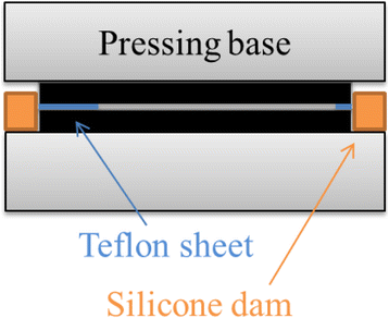
Schematic illustration for specimen fabrication.
-
6.
Sufficient pressure, approximately 0.53 MPa (15 MPa-gage pressure), was applied to the area (25 × 200 mm2) to achieve good adhesive distribution over the surfaces of the plates and kept for the required time to cure each adhesive.
-
7.
The bonded plates were released and cut it into specimen size of 25 mm in width.
-
8.
Two piano hinges were installed on the 25 mm pre-cracked side to an obtained specimen of the final shape as shown in Figure 1.

Experimental procedure
For mode I tests of the DCB specimens, a mechanical material testing machine (AGS-500A, Shimadzu Co., Ltd., Japan) was utilized. The specimen was fixed with mechanical grips, as shown in Figure 3, and loaded in the tensile direction with a constant displacement rate of 5 mm/min. The load and displacement were simultaneously recorded with a frequency of 1 Hz. For each type of specimen, three tests were carried out to obtain average value and standard deviation of critical fracture energy.

Mode I test of DCB specimen consisting of GFRTP.
Results and discussion
Figure 4 shows fractured surfaces of specimens A, B, BP, C and CP. For specimens A, B and BP, adhesive fracture between adherends and adhesives was mostly observed. In contrast, mix of adhesive and cohesive fracture was observed on the fracture surfaces of specimens C and CP. Polyamide 6, which is the matrix resin of the adherends, has relatively small amount of functional groups that contribute to adhesion, comparing from other thermoset matrix resins such as epoxy and polyester. Therefore, the interfacial strengths between adhesive and the adherends are low, and adhesive fracture occurs easily. Primer P can chemically activate the surface of the adherends and increases the interfacial strength to adhesive. The stronger interface leads to the cohesive fracture for specimens CP.

Fracture surfaces of different types of specimens.
Load–displacement curves of specimens A, B, BP, C and CP are shown in Figures 5, 6, 7, 8, 9. These figures include all the data for each experiment and suffixes 1, 2 and 3 indicate the specimen number. Specimens A and B exhibited similar load–displacement curves, as shown in Figures 5 and 6. The load–displacement curves of specimens A were quite smooth because crack propagation occurred continuously, and it resulted in small deviation in load and high repeatability. In contrast, for specimens B, crack propagated intermittently, which leaded to large deviation and low repeatability. Specimen C had higher maximum load and displacement, as shown in Figure 8, so that adhesive C is stronger and more ductile than adhesives A and B. Comparing Figures 6 and 8 with Figures 7 and 9, the maximum loads and displacements largely increased using primer P with adhesives B and C.

Load–displacement curves from specimens bonded with adhesive A.

Load–displacement curves from specimens bonded with adhesive B.

Load–displacement curves from specimens bonded with adhesive BP.

Load–displacement curves from specimens bonded with adhesive C.

Load–displacement curves from specimens bonded with adhesive CP.
To calculate the critical fracture energy of the specimens, an approach based on LEFM was applied. Energy release rate, g, which is the amount of energy per unit crack area created by a growing crack can be shown as
for systems which energy dissipation is limited to the crack tip region. Here, W is the external work, U is the stored elastic energy, and A is the crack area. The crack will propagate when this applied energy release rate reaches the critical value, g C , related to the fracture toughness in mode I, g I .
For a bonded configuration in which the load and deflection are linearly related, the value of mode I energy release rate g I is given by, according to LEFM:
where P is the load, B is the width of DCB specimen, a is the crack length, and C is the compliance, given by
where δ is the displacement corresponding to a load P. From simple beam theory, the value of the compliance C is given by
where E is the young’s modulus of adherend and I is the second moment of area, I = Bh 3/12, where h is the thickness of adherend. Then the energy release rate in mode I becomes
In the experiments, since relatively soft adhesives were utilized, the crack tips were difficult to identify visually, the process zones were quite large. Thus, it was difficult to calculate g I from visually observed crack length. Chaves et al. proposed a crack equivalent method by energy release rate can be determined without crack length even for mixed mode conditions [19]. Based on the theory proposed by Chaves and the simple beam theory, a following method that is simpler and can be used only for mode I loading was derived and applied to the test results.
To eliminate the need of monitoring the change in crack length for the ease of result analysis, substituting a by applying simple beam theory (modification of Eq. (4)), where a is given by
By substituting Eq. 6 into Eq. 5, mode I energy release rate can be expressed by
which the crack length, a, is no longer required for energy release rate calculation. Equation 6 is applicable only to DCB specimens having thin adherends whose deformation can be explained by the simple beam theory. That is the limitation of the proposed method.
Mode I critical fracture energy g IC vs. displacement curves of the specimens were then obtained based on Eq. (7), as shown in Figures 10, 11, 12, 13, 14 accordingly. This varied curves were then averaged by using area under the curve divided by displacement and the results are denoted by g IC,avg. The results of three experiments for each adhesive are shown in Table 2. Three results of g IC,avg were then again averaged (g IC,avg average) in each type of specimens and are shown in Table 2 and Figure 15. Comparing all the results of critical fracture energy, adhesive C (Plexus AO420) had the highest value, adhesive A (Sikaflex-252) was in the second position and adhesive B (Plexus MA300) in the third, although the difference between those of adhesives A and B was not significant. The average critical fracture energy of adhesive C was 918 J/m2, which is not smaller than those of ordinary epoxy adhesives, and the values of adhesive B, which was the smallest, was 403 J/m2 that is quite similar to the typical critical fracture energy of brittle epoxy adhesive. Thus, the used adhesives, polyurethane and acrylate, are not inferior to epoxy adhesives in terms of critical fracture energy for joining PA6 based GFRTP. They may be utilized for structural purposes instead of epoxy adhesives.

Critical fracture energies with respect to displacement from specimens bonded with adhesive A.

Critical fracture energies with respect to displacement from specimens bonded with adhesive B.

Critical fracture energies with respect to displacement from specimens bonded with adhesive BP.

Critical fracture energies with respect to displacement from specimens bonded with adhesive C.

Critical fracture energies with respect to displacement from specimens bonded with adhesive CP.

Comparison of overall-average mode I fracture critical energies.
The effect of primer P was drastic because the use increased the critical fracture energies of adhesive B and C approximately three times. The results show that the combination of adhesive C (Plexus AO420) and primer P (Plexus Primer PC120) exhibited the strongest value of 2.95 kJ/m2 that is much higher than those of ordinary epoxy adhesives and not inferior to the critical fracture energy of the most ductile epoxy adhesives such as CTBN modified epoxy adhesives.
Adhesive A (Sikaflex-252), which is polyurethane, was not combined with any primer in this research. The reason is only due to the situation that the authors did not have any primer appropriate for polyurethane adhesives. Polyurethane adhesives are usually utilized with surface treatment methods such as flame treatments and surface primers when applied to thermoplastics because the materials have low surface energy and are difficult to bond. The possibility that adhesive A exhibits higher strength with surface treatments cannot be denied. Thus, the results of this research do not imply the superiority of acrylate adhesives to polyurethane adhesives, but demonstrate the applicability of those types of adhesives to structural use.
Conclusions
In this research, the strength of adhesively bonded joints between PA6 based CFRTP adherends was experimentally investigated in terms of mode I critical fracture energy. The adherends were bonded with three different types of adhesives: adhesive A (Sikaflex-252), adhesive B (Plexus MA300) and adhesive C (Plexus AO420). A surface pretreatment with primer P (Plexus Primer PC120) matching to the use of three types of adhesives were carried out and studied for its applicability. When it comes to strength measuring in adhesive bonded joints, rather than considering in stress-base method, an approach to the design for strength of a structure, based on linear elastic fracture mechanic (LEFM) were applied. Mode I DCB tests were conducted to study and confirm joint strength from the various bonding methods. From this research, the following conclusions can be obtained.
-
1.
PA 6 based thermoplastic composites can be bonded by adhesive. The strength is not weak even if surface treatment is not applied and very high when proper surface treatment is applied and it matches to the type of adhesive.
-
2.
Acrylate adhesives B (Plexus MA300) and C (Plexus AO420) have enough strength compared with ordinary epoxy adhesives. The critical fracture energies without primer treatment are 403 J/m2 for adhesives B and 918 J/m2 for adhesives C.
-
3.
Polyurethane adhesive A (Sikaflex-252) has a critical fracture energy of 577 J/m2, which is higher than that of adhesives B.
-
4.
When primer P (Plexus Primer PC120) is used, the critical fracture energy of DCB specimens increases much. For instance, adhesives B with primer P and adhesives C with primer P exhibited 1.27 kJ/m2 and 2.95 kJ/m2 in critical fracture energy, respectively. The values are approximately three times to those without primer treatment.
-
5.
The critical fracture energy with adhesive C and primer P, i.e. 2.95 kJ/m2 is not inferior to the maximum values obtained from sophisticated ductile epoxy adhesives modified with rubber particles.
References
Beardmore P, Johnson C (1986) The Potential for Composites in Structural Automotive. Compos Sci Technol 26:251–281
Feraboli P, Masini A (2004) Development of carbon/epoxy structural components. Composites: Part B 35:323–330
Barnes T, Pashby I (2000) Joining techniques for aluminium spaceframes used in automobiles. J Mater Process Technol 99:72–79
Yousefpour A, Hojjati M, Jean-Pierre I (2004) Fusion Bonding/Welding of Thermoplastic Composites. J Thermoplast Compos Mater 17:303–341
Ageorges C, Ye L, Hou M (2001) Advances in fusion bonding techniques for joining thermoplastic matrix. Composites: Part A 32:839–857
Molitor P, Barron V, Young T (2005) Surface treatment of titanium for adhesive bonding to. Int J Adhes Adhes 21:129–136
Anderson T (2005) Fracture Mechanics. CRC Press, Florida
Dillard DA (2005) Fracture mechanics of adhesive bonds. in Adhesive bonding, ed. R. D. Adams, 190–208. Woodhead Publishing, Cambridge
Blackman BRK, da Silva LFM, Ochsner A, Adams RD (2011) Fracture Tests. In: Handbook of Adhesion technology. Springer-Verlag, Heidelberg, pp 474–501
Blackman BRK (2012) Quasi-Static Fracture Tests: Double Cantilever Beam and Tapered Double Cantilever Beam Testing. In: da Silva LFM, Dillard D, Blackman B, Adams R (eds) Testing Adhesive Joints. Wiley-VCH Verlag & Co, Weinheim, pp 170–174
Blackman BRK, Dear J, Kinloch A, Osiyemi S (1991) The calculation of adhesive fracture energies from double-cantilever beam test specimens. J Mater Sci Lett 10:253–256
Blackman BRK, Kinloch A, Paraschi M, Teo W (2003) Measuring the mode I adhesive fracture energy of structural adhesive joints: the results of an international round-robin. Int J Adhes Adhes 23:293–305
Hashemi S, Kinloch A, Williams J (1990) The analysis of interlaminar fracture in uniaxial fibre-polymer composites. Proceeding of the Royal Society A 427:173–199
Williams J (1988) On the calculation of energy release rates for cracked laminates. Int J Fract 36:101–119
PC-120 Technical Data Sheet. ITW Plexus, Massachusetts.
Sikaflex-252 Elastic Adhesive Technical Data Sheet. Sika Corporation. Michigan.
MA300 Technical Data Sheet. ITW Plexus. Massachusetts.
AO420 Technical Data Sheet. ITW Plexus. Massachusetts.
Chaves FJP, de Moura MFSF, da Silva LFM, Dillard DA (2013) Numerical validation of a crack equivalent method for mixed-mode I + II fracture characterization of bonded joints. Eng Fract Mech 107:38–47
Acknowledgements
Sika Japan Ltd. and ITW Performance Polymers & Fluids Japan are greatly acknowledged for providing us adhesives.
Author information
Authors and Affiliations
Corresponding author
Additional information
Competing interests
The authors declare that they have no competing interests.
Authors’ contributions
SM and KS made the specimen and carried out the experiments, SH prepared the experiment setup, YS and CS help for SM and KS to derive the equations and to write the paper.
An erratum to this article is available at http://dx.doi.org/10.1186/s40563-015-0038-0.
Rights and permissions
Open Access This article is licensed under a Creative Commons Attribution 4.0 International License, which permits use, sharing, adaptation, distribution and reproduction in any medium or format, as long as you give appropriate credit to the original author(s) and the source, provide a link to the Creative Commons licence, and indicate if changes were made.
The images or other third party material in this article are included in the article’s Creative Commons licence, unless indicated otherwise in a credit line to the material. If material is not included in the article’s Creative Commons licence and your intended use is not permitted by statutory regulation or exceeds the permitted use, you will need to obtain permission directly from the copyright holder.
To view a copy of this licence, visit https://creativecommons.org/licenses/by/4.0/.
About this article

Cite this article
Mahaphasukwat, S., Shimamoto, K., Hayashida, S. et al. Mode I critical fracture energy of adhesively bonded joints between glass fiber reinforced thermoplastics. Appl Adhes Sci 3, 4 (2015). https://doi.org/10.1186/s40563-015-0036-2
Received:
Accepted:
Published:
DOI: https://doi.org/10.1186/s40563-015-0036-2