
Abstract
Robot operating environments and the status of robots are complex and varying, so it is practically impossible for a robotics designer to anticipate all system configurations to successfully complete a task prior to deployment. Therefore, a mechanism for dynamic decision making and configuration synthesis that copes with system fault and uncertainty is necessary. This paper implements such a mechanism within a self-adaptive framework (ReFrESH). The goal of this presented mechanism is to provide diagnosability and maintainability to manage the system performance during task execution in the presence of unexpected uncertainties. Specifically, the functionality of the proposed mechanism include: (1) detection of system performance degradation; (2) diagnosis and locate of the fault module; (3) synthesis of feasible task configurations; (4) selection of the optimal one. We illustrate the feasibility of the proposed mechanism through a visual servoing task.
1 Introduction
Autonomous robotic systems are playing increasingly important roles in space, military, and Urban Search and Rescue (USAR) missions (Michael et al. 2012; Zhang and Parker 2013). At the same time, there is growing concern for system reliability during operation in such unpredictable environments. For instance, the dense dust caused by an unexpected wall collapse in an unstructured room may block the camera on an unmanned ground vehicle (UGV) and affect the survivor search mission. Furthermore, due to the large configuration combination space of a task for robotic systems, exhaustive testing of all combinations is general impractical (Nie and Leung 2011). Therefore, to increase reliability, robotic systems will require high-level decision making capabilities to dynamically react to unexpected situations that emerge in both the system and environment, while also automatically preserving the health of the system. In this way, successful task completion can be guaranteed.
The method of increasing reliability through on-line decision making and dynamic maintenance mentioned above has been widely studied in the field of multi-robot systems, namely in the area of robot coalition (Gerkey and Mataric 2002; Vig and Adams 2006; Zhang and Parker 2012). In order to help a robotic system, which consists of either a single robot or multiple robots, to accomplish tasks in a not fully anticipated environment, a mechanism for decision making and system maintenance should: (1) possess knowledge and real-time performance data about the system and task, such as resource efficiency and required module performance, to support detection of a system fault; (2) locate the system fault to reduce the cardinality of search space that can construct the new task configurations; (3) generate feasible task configurations that enable accommodation of unexpected contingencies during execution; and (4) cope with modules within a single robot, as well as modules across multi-robot networks, considering their physical and logical dependencies.
To this end, we propose a mechanism for decision making and system maintenance that is based upon the Reconfiguration Framework for distributed Embedded systems for Software and Hardware (ReFrESH) framework and its related work, the Embedded Virtual Machine (EVM) (Cui et al. 2012, 2013, 2014a; He et al. 2012; Mangharam and Pajic 2009).
ReFrESH is a self-adaptive framework aimed at managing the performance of robotic systems through dynamic diagnosis and maintenance of unexpected issues of modules in a task configuration (Cui et al. 2013, 2014a). As shown in Fig. 1, ReFrESH extends the familiar layered execution model to include (1) specific mechanisms for self-evaluation of the performance of execution units “in-vivo” at the component layer (Evaluator); (2) specific mechanisms for estimation of the expected performance of execution units prior to execution “in-vitro” at the component layer (Estimator); and (3) extended interfaces for decision making and system configuration synthesis at the task layer (Decider and Generator).

Layered ReFrESH architecture to support self-adaptation and dynamic decision making
EVM provides runtime mechanisms for control and actuation algorithms to adapt and reorganize resource utilization in the face of planned changes (e.g. mode changes, plant output targets) and unplanned changes (e.g. link and node outages) (Mangharam and Pajic 2009). This capability allows for reliable wireless network control and is achieved by decoupling functionality, so communication, computation and coordination may be maintained across physical node boundaries. We intend to provide the EVM method in ReFrESH so as to standardize the programming interfaces and synchronize connectivity between the heterogeneous categories of hardware platforms.
With the support of the aforementioned prior works for the framework and inter-node communication, this paper mainly focuses on the challenge of designing a mechanism for decision making and system maintenance from the following perspectives:
-
1.
Design a new component paradigm to provide knowledge of module performance and resource consumption to support runtime decision making;
-
2.
Design an algorithm to determine the performance degradation in a system and to locate the fault source to reduce the configuration search space;
-
3.
Design an algorithm to generate new system configurations and choose an optimal configuration to maintain the system.
The rest of this paper is organized as follows. Section 2 presents a review of related work regarding fault detection and location, configuration synthesis, and fault mitigation. In Sect. 3, a motivating example is proposed and we formalise the problem addressed in this paper. Section 4 presents the details of decision making mechanism. Section 5 introduces the built-in maintenance mechanisms of ReFrESH both from software and hardware accelerator perspectives. The experimental analysis that validates the feasibility of ReFrESH is presented in Sect. 6. We then conclude and list the future work in Sect. 7.
2 Related work
Decision making is a broad research area. In this paper, we mainly focus on using decision making to increase the reliability of a robotic system in terms of detecting and locating faults in a system task configuration, synthesizing feasible configuration candidates, and mitigating faults.
2.1 Fault detection
There is extensive valuable research to detect faults in a system. The Rainbow (Garlan et al. 2004) uses an abstract model to monitor an executing software system’s runtime properties and evaluates the model for constraint violation. Kieker van Hoorn et al. (2012) provides the necessary monitoring capabilities and the tools and libraries for the analysis and visualization of monitored data. KAMI (Epifani et al. 2009) can continuously monitor and analyse data at runtime to detect system faults. ReFrESH (Cui et al. 2014a) provides a framework to monitor task performance based on each executing module, which makes it possible for the system to target and diagnose the source of the fault. In this paper, based upon ReFrESH, we provide a new module design abstraction to support dynamic monitoring and evaluation of the performance of a system.
2.2 Fault location
Once the faults has been detected, the next step in designing a fault-tolerant system is to locate(identify) the fault (McIntyre et al. 2005). Here, due to the simplicity of implementation in the resource constrained systems, we focus on the fault location method through executing feasible test cases. In this type of method, the fault location accuracy is related to the number of coverage of test cases. The more test cases generated, the more precise result we can obtain. However, covering all the test cases is an NP-hard problem (Nie and Leung 2011). Thus, to efficiently locate faults, there are several outstanding methods. The base choice (BC) (Grindal et al. 2006) strategy generates test cases by only modifying a single module at a time. It is efficient in the scenario in which only one fault has emerged in the system. Automatic efficient test generator (AETG) (Tung and Aldiwan 2000) contains a heuristic algorithm for generating a test suite that satisfies pair-wise coverage. It finds one new test case per iteration, attempting to find a test case that maximizes the increase in pair-wise coverage. Several test case candidates are identified and evaluated. In this paper, we assume a single fault occurs in the system. Thus, the BC strategy is adapted to locate the fault in a system configuration.
2.3 Fault mitigation
The three-layer framework (Kramer and Magee 2007) is one of outstanding work. It presents a self-adaptive architecture that enables components to automatically configure their interaction in a way that is compatible with an overall architectural specification and achieves the goals of the system. ALLIANCE Parker (1998) provides a software architecture that facilitates cooperative control of teams of mobile robots for fault tolerance and allows each robot to select its appropriate action on the fly. Georgas and Taylor (2008) demonstrates an architecture-based self-adaptive system that focuses on supporting change of adaptation policies at runtime that are decoupled from the architectures they relate to. These self maintenance approaches are defined in the single robot view although they could potentially be used for multiple robots. In ReFrESH (Cui et al. 2014a), self adaptation methods for both single robot and multi-robot systems through use of EVM techniques are proposed along with hardware accelerator dynamic reconfiguration.
3 Motivating example and formalism of the problem
In this paper, we mainly use the single task application scenario. To motivate the need for the proposed mechanism for decision making and system maintenance under ReFrESH, we introduce a visual servoing application, which is defined as a single task and is coherently accomplished by a team of robots. We then formally define the problem we should address for this visual servoing application by using the proposed mechanism.
3.1 Visual servoing application
The objective of this application is to detect different targets and move robot to face to the targets with the optimal task configuration. For the purposes of this discussion, we assume that each target is marked by a unique characteristic (we use different shape) and each robot is assigned to a different initial target and then from left to right direction to detect all the targets circularly. We assume that each robot is preprogrammed with an initial task configuration without any coalition with other robots. We further assume that sensors and communication on each robot can be turned off manually, as well as the environment can be changed dynamically to simulate faults in the system. For example, we can shut down the camera on a robot or inject dense fog in front of destination location.
The visual servoing application is implemented by a series of modules. Each module can be allocated to every robot in the system. Thus, when determining the system performance degradation and generating new task configurations, we need to consider the whole system of robots instead of considering a single robot functioning independently. Additionally, when multiple feasible configurations are available, the mechanism must determine which is the best fit to the current situation.
Note that from our perspective, though we assume that initially each robot is preprogrammed with a configuration, a task cannot be defined in advance as running on a single robot or running on multi-robot cooperatively. Instead, whether or not a task runs on multiple robots depends on the capability and the current status of a robot. Some robots may be able to detect and face to target on their own while another robot whose malfunctioned may need assistance from the other robots. Our proposed mechanism in ReFrESH is able to determine the system performance, the cause of performance degradation, find combinations of modules based upon the capability of the whole system to generate feasible task configurations, and then decide the best configuration to re-instantiate on the robots.
3.2 Formalism of the problem
We formally define the problem we should address with the proposed decision making and system maintenance mechanism:
-
\(R = \left\{ R_1, R_2, \cdots R_n \right\} \) shows a collection of n robots in a system, where \(R_i\) represents a single the robot in a system.
-
\(R_i = \left\{ RE, SS, AS, CS \right\} \), a robot \(R_i\) is modeled by:
-
RE The set of resources on a robot, such as node computation capability, power capacity, communication methods.
-
SS The set of sensor schemas a robot contains. For example, eye-in-hand CCD camera schema, laser range finder schema.
-
AS The set of actuator schemas a robot has. For example, DC motor schema, RC motor schema.
-
CS The set of computation schemas a robot has. For example, image filter schema, template matching schema.
-
-
\(T = \left\{ SM, \bigcup (R_i:SS_i), \bigcup (R_i:AS_i), \bigcup (R_i:CS_i) \right\} \) denotes the task specification that one robot should achieve and is composed of:
-
\(SM = \left( S_1 \rightarrow S_2 \rightarrow \cdots \rightarrow S_n \rightarrow S_1 \cdots \ \right) \) is a state machine, \(S_i\) is one of the states. SM is executed continuously based on the proper state order and event-based transition condition of a task. For example, \(S_i \prec S_j\) means that after completing \(S_i\) and based upon the event condition generated, the task transitions to \(S_j\).
-
\(\bigcup (R_i:SS_i)\) shows a group of required sensor schemas on one or multiple robots (\(R_i:SS_i\)) to achieve a task.
-
\(\bigcup (R_i:AS_i)\) shows a group of required actuator schemas on one or multiple robots (\(R_i:AS_i\)) to achieve a task.
-
\(\bigcup (R_i:CS_i)\) shows a group of required computation schemas on one or multiple robots (\(R_i:CS_i\)) to achieve a task.
-
-
\(C = \left\{ C_1, C_2, \cdots , C_n \right\} \) gives the configuration search space that helps the decision maker choose the optimal task configuration, where \(C_i\) is one of the generated feasible task configuration candidates.
\(C_i = \left\{ Module_1, Module_2, \cdots Module_n \right\} \) is an assembly of the required modules of all the schemas that are defined in the task specification T.
-
\(P_{T}\) defines a task configuration quality function, which enables the decision maker to determine whether a configuration satisfies the task requirement or not. Two types of system performance are considered in the quality function:
Table 1 Decision making and system maintenance in ReFrESH -
\(P_{NF_k}\) is the non-functional performance of a system. It measures utilization of the kth resource on a robot, such as the power consumption or computational requirement. If utilization is less than the remaining capacity of the resource, the requirement of the system is satisfied, else it is not.Thus, \(P_{NF_k}\) is a binary value:
$$\begin{aligned} P_{NF_k} = {\left\{ \begin{array}{ll} 1, &{}\quad \mathrm{Resource\; k\; requirement\;is\;satisfied.}\\ 0, &{}\quad \mathrm{otherwise.} \end{array}\right. } \end{aligned}$$(1) -
\(P_{F_j}\) is the functional performance of a system which measures system performance according to the jth task-related metric, such as distance given to a target or template matching error. The task-related metrics are threshold values that are defined by the application designer. If \(P_{F_j}\) is larger than the threshold for that metric, the requirement of the system is satisfied, else it is not. Thus, \(P_{F_j}\) is a binary value as well:
$$\begin{aligned} P_{F_j} = {\left\{ \begin{array}{ll} 1, &{}\quad \mathrm{Metric\; j\; requirement\;is\;satisfied.}\\ 0, &{}\quad \mathrm{otherwise.} \end{array}\right. } \end{aligned}$$(2)To determine the feasibility of a configuration in the search space, Eq. (3) is used. If \(P_{T} = 1\), the configuration on this robot is valid and satisfies the system requirement; otherwise, the configuration is invalid and does not satisfy the system requirement.
$$\begin{aligned} P_T = \left( \prod _{k=1}^{n}P_{NF_k}\right) \bigcap \left( \prod _{j=1}^{m}P_{F_j}\right) ={\left\{ \begin{array}{ll} \mathrm{Satisfy}, &{}\quad 1.\\ \mathrm{Not \; satisfy}, &{}\quad 0. \end{array}\right. } \end{aligned}$$(3)
-
-
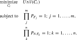
Given a feasible task configuration search space C, we define a utilization function \(Util(C_i)\) for each \(C_i\subset C\). We again consider this function in two parts:
-
\(Util_{NF_k}(C_i)\) measures the resource cost of \(C_i\), such as power consumption and computational requirement.
-
\(Util_{F_j}(C_i)\) measures the task-related functional cost of \(C_i\), such as distance to a target.
-
The overall cost of \(C_i\), \(Util(C_i)\), is the weighted summation of all \(Util_{NF_k}(C_i)\) and \(Util_{F_j}(C_i)\), with the weighting parameter \(\alpha \) defined by the application designer, as shown in Eq. 4:
$$\begin{aligned} Util\left( C_i \right) =\alpha \sum _{k=1}^{n}Util_{NF_k} \left( C_i \right) + \left( 1-\alpha \right) \sum _{j=1}^{m}Util_{F_j} \left( C_i \right) \end{aligned}$$(4)For the decision making process, we should choose the configuration in the search space which is the best fit for the current situation by:
 (5)
(5)
-

4 The approach: diagnosis–synthesis-decision making
To increase the reliability of task completion for a system (single robot or multi-robot), based upon ReFrESH, we propose a mechanism that consists of three main steps as shown in Table 1.
In ReFrESH, a module database is maintained as a tree data structure. Each module specifies its domains, such as the schemas it belongs to and which robots it can be instantiated on, as shown in Fig. 2. From this tree structure, we can retrieve the alternatives of a module easily by checking their common ancestor. For example, in Fig. 2, for robot \(R_{n-2}\), module \(M_2\) and \(M_{p-1}\) have the same parent sensor schema \(SS_j\), so \(M_2\) and \(M_{p-1}\) can only be instantiated either one in a configuration \(C_i\), but they are interchangeable; also, \(M_2\) has two children robot \(R_1\) and \(R_{n-2}\), so \(M_2\) can be instantiated on \(R_1\) or \(R_{n-2}\). Therefore, if we should modify \(M_{p-1}\) to \(M_2\) in \(C_i\), it generates two cases: instantiate \(M_2\) on \(R_{n-2}\) or instantiate \(M_2\) on \(R_1\) which means the \(C_i\) on \(R_{n-2}\) is a coalition of \(R_1\) and \(R_{n-2}\).

Modules database in the form of tree data structure
Furthermore, every step of decision making and system maintaining are closely related to a new component design abstraction, we named extend port-based object (E-PBO). Therefore, in this section, we introduce the E-PBO firstly, and then illustrate the details of the decision making approach.
4.1 Extended port-based object
The port-based object (PBO) (Stewart et al. 1997) is a module design abstraction which consists of an independent concurrent process whose functionality is defined by the methods of a standard object, as well as the ports: (1) using port-automation theory, one module’s connection (communication) to other modules is restricted to its variable input ports and variable output ports; (2) the configuration constants ports are used to reconfigure generic components for use with specific hardware or applications; (3) the resource ports are for communication with sensors and actuators via peripheral drivers.
The reliability and performance of a system in accomplishing a task is closely related to the reliability and performance of each module. As previously stated, we divide the performance of a system into two perspectives: (1) non-functional performance, which is related to the physical resources of a system. For instance, the remaining power in regard to the power consumption of all the modules on a robot or the communication link quality with other robots; (2) functional performance, which is related to how efficiently a system completes a task based on the user specification. For example, a camera blocked by dust that produces very noisy image will degrade the performance of a target detection module and affect the visual servoing task execution. Both non-functional performance and functional performance of a system are affected by the runtime resources and functional output characteristics of each module. Therefore, to provide knowledge of module performance and resource consumption to support runtime decision making, the E-PBO is modelled after the PBO.
As shown in Fig. 3, the E-PBO is composed of two parts. The first is a conventional PBO Executor (EX), which defines the functionality and provides ports to communicate with other actively executing E-PBOs, reconfigure the module constants, or connect to sensors/actuators. The other part is the extension to the PBO, which consists of the E-PBO Evaluator and the E-PBO Estimator.

Abstract view of an E-PBO. Subscript f denotes functional performance and nf denotes non-functional performance
4.1.1 E-PBO evaluator
The E-PBO evaluator (EV) evaluates the performance of an E-PBO and it is triggered only if its corresponding E-PBO is executing. EV does not need to take input(s) from other E-PBOs since it only evaluates performance based upon the variable output ports of its own E-PBO. Thus, EV only includes evaluator performance output ports, which are needed to supply the functional performance (such as target detection accumulated error) and non-functional performance (required power usage versus system power capability). Furthermore, EV does not communicate with other E-PBOs, but instead connects to a system management unit, such as the Decider in ReFrESH. The outputs of EV provide the evidence for self-adaptation to the system to determine if the performance of a task configuration is satisfactory or not.
4.1.2 E-PBO estimator
The E-PBO estimator (ES) estimates the performance of an E-PBO and it can be used by both running and non-running E-PBOs. It is triggered only if the current running task configuration could not satisfy the performance requirement and a new task configuration is generated by a configuration generation unit, such as the Generator in ReFrESH. ES includes the same functionality of its corresponding E-PBO as well as standalone sets of ports, estimator variable input ports and estimator variable output ports, which connect and communicate with other ES’s, and estimator performance output ports that provide the functional performance values to a system management unit, such as the Decider in ReFrESH. The reason there is no non-functional performance output from the ES is that only configuration from the configuration search space are estimated and all of these are know to be feasible. After connecting all of the ES in a potential configuration, the management unit of ReFrESH combines all the performance values from each ES to determine if the new task configuration is suitable or not. The ES of each E-PBO provides the recommendation for self-adaptation so that it can determine which new configuration should be used in the presence of faults in place of the current configuration.
A sample library of E-PBOs for a robotic visual servoing application is shown in Fig. 4, which is a subset of the E-PBOs that were created in our laboratory at Purdue. In order to clearly illustrate the proposed decision making and system maintenance mechanism, we have visual servoing task configuration composed of several E-PBOs (for a description of each E-PBO please refer to Fig. 4) in the layered format of ReFrESH, as shown in Fig. 5.

Sample library of E-PBOs for the robotic visual servoing application

A sample configuration built by E-PBOs which is running in ReFrESHs
4.2 Decision making phase 1: monitor running configuration
As previously stated, in this paper, we focus on the scenario in which each robot accomplishes the same task with or without assistance from other robots. Therefore, given task T, a collection of robots R and current running configuration \(C_{current}\), ReFrESH is able to execute the first phase of decision making: Decide whether the system configuration satisfies the task performance requirement.
Each E-PBO EV runs at the same frequency as its E-BPO EX, which is predefined by the application designer. Although the outputs of all EVs are connected to the non-functional and functional performance buffers in the management unit (as shown in Fig. 5), based upon the application, the user can choose which task-related parameters should output to ReFrESH. For example, in the sample task configuration in Fig. 5, the power consumption \(EV_{power}\) of each module updates to the non-functional performance buffer and the output \(\theta _d\) and deviation \(EV_{diff}\) of module “TrajGen” update to the functional performance buffer. With all values available in two buffers, based on Eqs. (1), (2) and (3), “Decider” (in Fig. 5) can evaluate and determine whether the performance of a configuration for a task violates the requirement or not. If the \(C_{current}\) satisfies the performance requirements, ReFrESH keeps monitoring the \(C_{current}\); otherwise, the cause of the performance degradation should be located, which is illustrated in the next section.
4.3 Decision making phase 2: locate faulty module
Currently, the mechanism we propose here only handles the situation in which a single module causes performance degradation; two or more modules simultaneously affecting the task performance will be addressed in the future work. Therefore, we assume that only one module has a fault when the configuration violates the performance requirement and so we need to locate this module.
The process of locating the faulty module in this paper uses combination strategy to narrow down the fault module search space gradually. Grindal et al. (2006) demonstrates the comparison among several combination strategies in terms of case coverage and fault detection success rate. We choose the BC strategy due to its low case number and high fault detection success rate (Grindal et al. 2006).
The BC strategy requires every alternative of every module to be included in at least one test case and so the number of test cases is: (\(\sum _{i=1}^{n}a_i)-n\), where \(a_i\) is the number of alternatives of every module and n is the number of modules who have alternatives in \(C_{current}\) (Nie and Leung 2011). For example, as shown in Fig. 5, suppose all modules initially run on robot \(R_1\):
\(C_{current} = \left\{ CamReader, SSD, TrajGen, HexMan \right\} \). Suppose there are no alternatives of CamReader and HexMan and there are two and three the alternatives of SSD and TrajGen respectively. With this we get a total of \(2+3-2 = 3\) test cases instead of getting \(2*3 = 6\) test cases by using the brute force method. Without loss of generality, suppose we have n components and each of them has m alternatives, so by using the BC strategy, the search space is \(O(m(n-1))\); while using the brute force strategy, the search space is \(O(n^m)\). This shows that using the BC strategy can greatly reduce the search space to find the faulty module.
Provided with the module database from ReFrESH, the alternatives of each module can be obtained and the faulty module detection process can be executed as shown in Algorithm 1.

4.4 Decision making phase 3: find an optimal configuration
The faulty module found in Phase 2 can be seen as the seeding. In other words, the new system configuration candidates for a task can be synthesized by only modifying the seeding module and an optimal configuration exists in this candidates search space.
As presented in Sect. 4.1, the E-PBO uses the port-automata theory such that one module’s connection (communication) to other modules is restricted to its variable input ports and variable output ports. Thus, given the output(s) of the module that feeds into the seeding module and the input(s) of the module that is fed by the seeding module, by parsing the inputs/outputs of a set of modules, new combo modules (a new “module” which has the same inputs/outputs as the seeding module, but is a combination of more than one module) are generated. In this case, though the modules search space is reduced by finding a seeding module, due to the uncertainty of the number of combo modules, the module search becomes NP-hard again. Therefore, besides seeding, we also add a constraint to limit the number of modules in a combo module. For example, as shown in Fig. 4, since the outputs of the Dehazer module match the inputs of the SSD module, an Enhanced SSD module composed of the Dehazer and SSD can replace the single SSD module. However, since the Dehazer output matches its own input, the Dehazer could be cascaded together infinitely. In this case, the system would get stuck in this phase and will not arrive of any decision. For this reason we currently limit the number of modules in a combo to two.
With the seeding and this constraint, the configuration candidates can be generated and the greedy algorithm shown in Nie and Leung (2011) can be used to choose an optimal one. Algorithm 2 shows the process of phase 3 and after running algorithm, an optimal configuration \(C_{update}\) is returned. In Algorithm 2, \(Module_p[i]\) is defined as an alternative of \(Module_p\).

5 ReFrESH built-in maintenance approaches
After an optimal configuration \(C_i\) generated from the proposed mechanism, to run it, some modules may need to migrate to and instantiate on the different robots. ReFrESH provides methods to support software module adaptation as well as hardware accelerator dynamic reconfiguration to maintain the system.
5.1 Software adaptation
Software adaptation refers to the runtime software downloading and installation of reusable software modules that are not compiled into the existing executable running on an embedded system (SWEX in Fig. 1). This requires support from both the operating system and the communication subsystem. The PBO (Stewart et al. 1997) framework of the PBO/RT OS provides a good basis for component migration in embedded and real-time systems because it encapsulates the methods needed to control periodic and non-periodic tasks into a uniform programming interface that is easily ported. E-PBOs in ReFrESH are object-oriented software modules based on port automata. Port automata can represent a broad class of arbitrary processes, so we will restrict our attention to tasks based upon them.
Every embedded system, such as a robotic system, requires some method to download code during development and ours is no exception. We generally use hex files [Intel HEX in microcontroller and MCS HEX in field programmable gate arrays (FPGA)] to download code to the CPU, so it was natural to use the hex file structure to implement code migration in PBO/RT. The format is simple and efficient to implement in real-time, it works on both lossy RS-232 and packet-based networks, it’s easy to control with an ASCII terminal, and the limited address range is not a problem for compact, real-time tasks.
The standard hex file specification allows for only six basic record types: data, end-of-file (EOF), extended linear address, start linear address, and two record types for Intel segmented addresses for legacy \(\times \)86 systems. We use only the data and EOF records for normal downloading. Since hex files are based on specific, located addresses, we augmented the file record structure to include two new commands: offset function pointer and module initialization pointer.

The Morphing bus structure is replicated internally on the FPGA to create the morphing crossbar. a When the external peripheral boards are plugged into the base board through the local crossbar, the responding internal modules interconnect together. b The same external boards when we swap the board order; the responding internal modules interconnection will change also
The offset function pointer record identifies the location of internal function pointers in the code that must be updated. Currently, there is no mechanism to link non-OS function calls, so all required subroutines must be included in the migrated object code. To build the “07” (offset) commands, note that the .map file indicates each function start address. So, the assignment of the function pointers occurs somewhere in the component initialization routine. The module initialization pointer is a pointer to the initialization subroutine that is unique to the PBO structure. This subroutine registers the module with the OS.
Upon receiving the file from the network, the OS loads the module into memory [flash memory, in the case of the ATmega or FPGA, which requires buffering the program code in SRAM or Block RAM (BRAM) and breaking it into 256-byte blocks] and spawns the PBO. At this point, the module is installed, initialized, and ready to run.
5.2 Hardware accelerator dynamic reconfiguration
With the proliferation of programmable logic and flash memory, it would seem that logic hardware reconfiguration is a trivial matter. In fact, many commercial systems permit system reconfiguration through FPGAs. But for real-time systems, dynamic reconfiguration remains a challenge as time-determinism does not allow for the entire system to be shut down while the FPGA is re-flashed. To achieve logic hardware adaptation for real-time robotic systems (HWEX in Fig. 1), only a part of the system can be reconfigured at runtime at any given instant.
We have been developing architectures and tools for hardware static and dynamic reconfiguration, which include the real-time operating system, application software, and the Morphing Bus for sensor/actuator robotic systems (Cui et al. 2014b). By mirroring the external Morphing Bus structure and combining a local crossbar inside a single FPGA, a new partial dynamic reconfiguration (PDR) architecture named Morphing Crossbar has been proposed, as shown in Fig. 6. It is important to point out that while the standard interface concept and circular routing of the Morphing Crossbar was inspired by our Morphing Bus for peripheral interconnection, it is not dependent on it and can be used in any application. Thus, through bitstream migration, we are able to dynamically load a bitstreamFootnote 1 on-demand through PBO/RT and map it to the hardware.
To address the problems of resource consumption and high timing overhead in the process of PDR, the Morphing Crossbar uses a hybrid mechanism that combines the low resource consumption of bus-based PDR mechanisms with the speed of a point-to-point crossbar. Specifically, each hardware component is separated into two parts: one part is responsible for the data flow and reconfiguration control (termed “wrapper”) and the other part is responsible for the data processing (termed “functionality”). The wrapper is connected to the corresponding function module. During PDR, instead of changing both parts for each component, by only changing the wrapper the system can achieve hardware component adding, removing, and swapping. This decreases the configuration (partial bitstream) size and so decreases the reconfiguration timing overhead. Also, this abstraction of the hardware module interface to the re-routing design pattern we have employed reduces consumption of internal resources and enhances hardware reusability. The details of the Morphing Crossbar design and implementation can be found in our previous work (He et al. 2012).
6 Experiments
To date, we have implemented a basic decision making and system maintenance mechanism within ReFrESH to increase the reliability of a two-robot system. This mechanism is validated through accomplishing a visual servoing task as shown in Sect. 3 by a two-robot systemFootnote 2. The performance metrics we considered here are (1) non-functional performance: power consumption \(P_{NFpower}\), and (2) functional performance: deviation in pixels from the target to the center of the image \(P_{Fdiff}\). Thus, staying consistent with the formalism in Sect. 3, the performance of a configuration for the task (\(P_T\)) and the utilization of a configuration (\(Util_C\)) are determined according to Eq. (6) through Eq. (10). To point out, \(\sum _{i=1}^{n}P_{NFpower}(M_i)\) is the summation of all the power consumption of modules (\(M_i\)) in a configuration C; 20 is a user defined threshold that is normalized in (0, 100) and shows the tolerance of leftover power in a system to guarantee performance; \(Loc_{target}\) is the horizontal location of the detected target in the picture frame, where (0, 0) is defined at the center of the image; 30 is the user defined maximum allowable deviation of pixels from the target to the image center along with horizontal (X) axis; and \(Util_{NFpower}\) shows the overall power utilization in a configuration.
where,
where,
Given the above equations, a robot running ReFrESH can incorporate the power consumption and target deviation information into the decision making and system maintenance process for the visual servoing task.
6.1 Hardware platform
The robotic platform used in this case study consists of a single sevoing rotation robot and the HexManipulator that was built in our laboratory, which is a form of Stewart–Gough platform (Dasgupta and Mruthyunjaya 2000) configured as defined by Uchiyama’s HEXA-Parallel-Robot (Pierrot et al. 1990; Last et al. 2005). The HexManipulator consists of six links where each link is a serial combination of a 1 DoF active rotary joint, a 2 DoF passive universal joint, and a 3 DoF passive spherical joint. All the links are connected to a base and travelling plate and are actuated by a total of six Futaba S3003 servo motors. An RGB camera which is capable of outputting 30 frames per second is fixed on the traveling plate as a vision sensor. The RecoNode (Voyles et al. 2010) is selected to run the PBO/RT operating system. The RecoNode is a high performance Reconfigurable Node, whose multiprocessor architecture is based on the Xilinx Virtex-4 FPGA with low-power, hardcore PowerPC CPUs and is capable of up to 1600 MIPS which is more powerful than microcontrollers. The hardware platform setting for a visual servoing application is shown in Fig. 7.

The hardware platform setting for a visual servoing application

The system error of a HexManipulator executing a visual servoing task
6.2 Software configuration
The applied task is to enable each platform to autonomously detect three targets cyclically and move from its current position to a goal position based on the angle between the current target and the next target. We mainly inject error to HexManipulator platform and mainly analyse proposed mechanism based on it. The system configuration involves several functionality, such as target detection (SSD E-PBO), trajectory generation (trajGen E-PBO), control of the physical HexManipulator platform (HexMan E-PBO), and runtime switching of the target template (using the resource port “template” of SSD E-PBO). Figure 5 has shown the initial system configuration for this task within ReFrESH. The “Decider” and “Generator ” (Fig. 1) in ReFrESH are running the proposed decision making and system maintenance mechanism. Furthermore, we provide a module database that consists of the modules in Fig. 4.
6.3 Fault detection and location
To test the methods of fault detection and fault location, we created an alternative for each E-PBO as shown in Fig. 5 except for HexMan, such as \(camReader\_alt\), \(SSD\_alt\), \(TrajGen\_alt\). We deliberately injected error into the system by adding noise into the CamReader module while the leftover power of system is 90, which is greater than 20, thus, according to Eq. (8), \(P_{NFpower} = 1\). We run a total of five trials under the exact same hardware and software configuration settings.
Due to the injection of noise in the image, the template matching module sum-squared difference (SSD) generates the location of target with larger error. This error propagates to the following modules and affects system performance. As shown in Fig. 8, after the noise is injected in the camReader module, around 4.4 s, the system detects the fault when the output of SSD is larger than the threshold, so \(P_{Fdiff} = 0\). Therefore, according to Eq. (6), \(P_T = 0\).
After the system fault is detected, Algorithm 1 runs to locate the fault by using BC strategy. A total of 3 test cases are generated by BC:
-
1.
\( \big \{CamReader\_alt, SSD, TrajGen, HexMan \big \}\)
-
2.
\( \big \{CamReader, SSD\_alt, TrajGen, HexMan \big \}\)
-
3.
\( \big \{CamReader, SSD, TrajGen\_alt, HexMan \big \}\)
Then, Algorithm 1 calls the E-PBO ES of each module, connects the estimator variable inputs/outputs accordingly (red line in Fig. 9) and accumulates all the estimated performance values (red dash line in Fig. 9). The advantage of the E-PBO module design abstraction is the separation of E-PBO EX variable input/output ports and ES variable input/output ports in that it allows running the estimation process without interfering with the execution of the current system configuration.

The running task configuration and the estimation process for a new non-running task configuration composed by E-PBOs. We use red wires to distinguish current running configuration and non-running configuration that needs estimate (Color figure online)

A new system configuration by swapping in a “Dehazer” E-PBO
In this experiment, configuration
\(C=\{CamReader\_alt, SSD, TrajGen, HexMan \}\) satisfies the performance requirement, so Algorithm 1 is terminated after finding the first configuration and returns the module CamReader as the faulty module.
6.4 Synthesize configuration candidates and choose an optimal one
With the seeding module detected in the previous section and given the module number constraint of a combo module, Algorithm 2 runs to generate the configuration candidates and uses greedy search to find an optimal configuration.
In this experiment, searching in the module database, based on output ports/input ports matching, two combo modules are constructed:
\(CamReader\_alt + Dehazer\);
\(CamReader + Dehazer\).
To point out, Dehazer is an image enhancement and noise cancellation module. Thus, three configuration candidates are generated as shown in the following:
-
1.
\( \big \{CamReader\_alt, SSD, TrajGen, HexMan \big \}\)
-
2.
\( \big \{CamReader, Dehazer, SSD, TrajGen, HexMan \big \}\)
-
3.
\( \big \{CamReader\_alt, Dehazer, SSD, TrajGen, HexMan \big \}\)
In the next step, Algorithm 2 generates an optimal configuration based on Eq. (10). The optimal configuration generated in this case is:
\(C = \big \{CamReader, Dehazer, SSD, TrajGen, HexMan \big \}\)
As shown in Fig. 8, once the optimal configuration C is instantiated, after 53.4 ms the system goes to the status that satisfies the task performance. The updated system configuration is shown in Fig. 10.
6.5 Discussion
Through this basic implementation, we justify the feasibility of our proposed decision making and system maintenance mechanism within ReFrESH. Though in this paper, it only involves two robots and five modules, compared to brute force combination method, we also can see the efficiency improvement by using BC strategy to locate the fault. In this case study, using brute force would generate 8 test cases, while using BC, there are only 3 test cases generated. For the general case analysis please refer to Sect. 4.3. Furthermore, with the seeding module and the constraint for the new combo module, our method reduces the search space for finding an optimal configuration.
7 Conclusion and future work
In order to increase the reliability of robotic systems, this paper presented a mechanism of decision making and system maintenance built in ReFrESH. This proposed mechanism could monitor the system performance and detect the abnormal status of the system. Also, when the fault is detected, the BC strategy based algorithm can locate the fault efficiently. Then based on the faulty module as a seed, and with the constraint of constructing a new combo module, all feasible configuration candidates can be generated and the greedy algorithm is used to choose an optimal configuration as the system maintaining configuration. Through a visual servoing application involving runtime fault detection and fault mitigation, we have demonstrated the utility of the proposed mechanism for fault tolerance in robotic systems.
Our ongoing work includes testing the feasibility and efficiency of proposed mechanism in some more complex application scenarios which involve more than two robots and over ten modules. We also will work on the fault location phase by using a more sophisticated method compared to the combination method, such as using neural networks to detect fault in the system. Furthermore, we will keep working on ReFrESH to have a better support of dynamic self-adaptation in robotic systems.
Notes
Bitstream is the compiled hardware accelerator module in FPGA.
For implementation please refer to GitHub: https://github.com/cuiyanzhe/ReFrESH.
References
Cui, Y., Voyles, R., He, M., Jiang, G., MH., M. (2012). A self-adaptation framework for heterogeneous miniature search and rescue robots. In Safety Security and Rescue Robotics (SSRR), 2012 IEEE International Workshop on SSRR (pp. 1–7).
Cui, Y., Voyles, R. & Mahoor, M. (2013). Refresh: A self-adaptive architecture for autonomous embedded systems. In Automation Science and Engineering (CASE), 2013 IEEE International Conference on CASE (pp. 850–855). doi:10.1109/CoASE.2013.6654042.
Cui, Y., Voyles, R., Lane, J. & Mahoor, M. (2014a). Refresh: A self-adaptation framework to support fault tolerance in field mobile robots. In Intelligent Robots and Systems (IROS 2014), 2014 IEEE/RSJ International Conference on IROS 2014 (pp. 1576–1582). doi:10.1109/IROS.2014.6942765.
Cui, Y., Voyles, R., Nawrocki, R., & Jiang, G. (2014b). Morphing bus: A new paradigm in peripheral interconnect bus. IEEE Transactions on Components, Packaging and Manufacturing Technology, 4(2), 341–351. doi:10.1109/TCPMT.2013.2273663.
Dasgupta, B., & Mruthyunjaya, T. (2000). The stewart platform manipulator: A review. Mechanism and Machine Theory, 35(1), 15–40.
Epifani, I., Ghezzi, C., Mirandola, R. & Tamburrelli, G. (2009) Model evolution by run-time parameter adaptation. In Proceedings of the 31st International Conference on Software Engineering, ICSE ’09 (pp. 111–121). Washington, DC: IEEE Computer Society. doi:10.1109/ICSE.2009.5070513.
Garlan, D., Cheng, S. W., Huang, A. C., Schmerl, B., & Steenkiste, P. (2004). Rainbow: Architecture-based self-adaptation with reusable infrastructure. Computer, 37(10), 46–54. doi:10.1109/MC.2004.175.
Georgas, J.C. & Taylor, R.N. (2008). Policy-based self-adaptive architectures: A feasibility study in the robotics domain. In Proceedings of the 2008 International Workshop on Software Engineering for Adaptive and Self-managing Systems, SEAMS ’08 (pp. 105–112). New York: ACM. doi:10.1145/1370018.1370038.
Gerkey, B., & Mataric, M. (2002). Sold!: auction methods for multirobot coordination. IEEE Transactions on Robotics and Automation, 18(5), 758–768. doi:10.1109/TRA.2002.803462.
Grindal, M., Lindstrm, B., Offutt, J., & Andler, S. (2006). An evaluation of combination strategies for test case selection. Empirical Software Engineering, 11(4), 583–611. doi:10.1007/s10664-006-9024-2.
He, M., Cui, Y., Mahoor, M. & Voyles, R. (2012). A heterogeneous modules interconnection architecture for FPGA-based partial dynamic reconfiguration. In Reconfigurable Communication-centric Systems-on-Chip (ReCoSoC), 2012 7th International Workshop on ReCoSoC (pp. 1 –7). doi:10.1109/ReCoSoC.2012.6322887.
Kramer, J. & Magee, J. (2007). Self-managed systems: An architectural challenge. In Future of Software Engineering, 2007, FOSE ’07 (pp. 259–268). doi:10.1109/FOSE.2007.19.
Last, P., Budde, C. & Hesselbach, J. (2005). Self-calibration of the hexa-parallel-structure. In Automation Science and Engineering, 2005, IEEE International Conference on Automation Science and Engineering, 2005 (pp. 393–398). doi:10.1109/COASE.2005.1506801.
Mangharam, R. & Pajic, M. (2009). Embedded virtual machines for robust wireless control systems. In Distributed Computing Systems Workshops, 2009, 29th IEEE International Conference on ICDCS Workshops ’09 (pp. 38–43). doi:10.1109/ICDCSW.2009.31.
McIntyre, M., Dixon, W., Dawson, D., & Walker, I. (2005). Fault identification for robot manipulators. IEEE Transactions on Robotics, 21(5), 1028–1034. doi:10.1109/TRO.2005.851356.
Michael, N., Shen, S., Mohta, K., Mulgaonkar, Y., Kumar, V., Nagatani, K., et al. (2012). Collaborative mapping of an earthquake-damaged building via ground and aerial robots. J Field Robot, 29(5), 832–841.
Nie, C., & Leung, H. (2011). A survey of combinatorial testing. ACM Computing Surveys, 43(2), 11:1–11:29. doi:10.1145/1883612.1883618.
Parker, L. (1998). Alliance: An architecture for fault tolerant multirobot cooperation. IEEE Transactions on Robotics and Automation, 14(2), 220–240. doi:10.1109/70.681242.
Pierrot, F., & Uchiyama, M. (1990). A new design of a 6-DOF parallel robot. Journal of Robotics and Mechatronics, 2(4), 308–315.
Stewart, D., Volpe, R., & Khosla, P. (1997). Design of dynamically reconfigurable real-time software using port-based objects. IEEE Transactions on Software Engineering, 23(12), 759–776. doi:10.1109/32.637390.
Tung, Y.W. & Aldiwan, W. (2000). Automating test case generation for the new generation mission software system. In 2000 IEEE Aerospace Conference Proceedings (Vol. 1, pp. 431–437). doi:10.1109/AERO.2000.879426.
van Hoorn, A., Waller, J. & Hasselbring, W. (2012). Kieker: A framework for application performance monitoring and dynamic software analysis. In Proceedings of the Third Joint WOSP/SIPEW International Conference on Performance Engineering, ICPE ’12 (pp. 247–248). New York: ACM. doi:10.1145/2188286.2188326.
Vig, L., & Adams, J. (2006). Multi-robot coalition formation. IEEE Transactions on Robotics, 22(4), 637–649. doi:10.1109/TRO.2006.878948.
Voyles, R., Povilus, S., Mangharam, R. & Li, K. (2010). Reconode: A reconfigurable node for heterogeneous multi-robot search and rescue. In Safety Security and Rescue Robotics (SSRR), 2010 IEEE International Workshop on SSRR (pp. 1–7). doi:10.1109/SSRR.2010.5981569.
Zhang, Y. & Parker, L. (2012). Task allocation with executable coalitions in multirobot tasks. In Robotics and Automation (ICRA), 2012 IEEE International Conference on ICRA (pp. 3307–3314). doi:10.1109/ICRA.2012.6224910.
Zhang, Y., & Parker, L. (2013). IQ-ASyMTRe: Forming executable coalitions for tightly coupled multirobot tasks. IEEE Transactions on Robotics, 29(2), 400–416. doi:10.1109/TRO.2012.2228135.
Acknowledgments
This work was supported by National Science Foundation Grants CNS-0923518, CNS-1450342 and IIS-1111568 with additional support from the NSF Center for Robots and Sensors for the Human Well-Being (RoSe-HUB).
Author information
Authors and Affiliations
Corresponding author
Rights and permissions
About this article

Cite this article
Cui, Y., Voyles, R.M., Lane, J.T. et al. A mechanism for real-time decision making and system maintenance for resource constrained robotic systems through ReFrESH. Auton Robot 39, 487–502 (2015). https://doi.org/10.1007/s10514-015-9472-x
Received:
Accepted:
Published:
Issue Date:
DOI: https://doi.org/10.1007/s10514-015-9472-x